
mechanical seal installation free sample
Have a clean area available for the components and ensure that there are no finger prints, oil or grease on the primary seal faces. Wipe with alcohol using a lint free cloth if necessary.
Primary seal face flatness will have been confirmed by the seal manufacturer and should be within 1-2 helium light bands. For this reason, the primary seal faces must be free of fingerprints, oil and/or grease.
Clean and de-burr the shaft area and seal chamber area as required using a solvent that will be compatible with the process fluid. (Note: Assure all piping/tubing is isolated from flush/quench ports. Plastic plugs need to be installed in all flush/quench after isolation of piping/tubing, up to the point of the piping/tubing reinstallation.
Proper spring compression check (‘working height’) – obtain dimension from seal drawing which shows the distance between the back of the seal retainer and the seal chamber face. Then fit the bearing bracket and shaft up against the casing and mark (with bluing pen) the point on shaft or sleeve directly below the seal chamber face. Remove shaft bearing bracket from casing and mark the dimension where the back of the retainer sits when assembled.
Attach seal head to shaft/sleeve and ensure that set screws are installed on clean and undamaged shaft areas. If this is not possible, carefully de-burr with a file and smooth out with emery cloth.
Install the stationary seal face into gland evenly to ensure face is not cocked. Assure that any finger prints are removed with alcohol and lint free towel.
Install gland to stuffing box using opposite and even tightening technique. Prior to doing so, a sweep of the seal chamber face is required to ensure proper sealing between gasket/’O’ ring on seal gland and seal chamber. A dial indicator should be attached to the shaft and the shaft will be rotated to cover a complete sweep of the seal chamber face. TIR should be no more than 0.005’.
After seal is completely installed, conduct a static pressure check. Consult the seal vendor for the proper pressure if static limit is not indicated on seal drawing. If any leaks are observed, consult seal vendor immediately.
Contaminated faces – can affect face flatness, resulting in excessive leakage. In addition, certain oils can set-up like adhesives and pull material out of the carbon primary ring faces after start-up, resulting in pre-mature seal failures.
Not setting proper spring compression: excessive compression – more seal wear. Low compression – will not provide sufficient face contact during start-up and standby conditions allowing excessive leakage.
Improper installation of mating ring into the gland resulting in excessive leakage due to improper face contact. Note that if back of mating ring is visibly ‘not flat’, the same result can apply. Stuffing box face TIR should be checked with dial indicator on shaft. Seal chamber face flatness should be no more than 0.005’ TIR.
Installation of gland to stuffing box not using equal and opposite tightening technique. Failure to tighten the nuts/capscrews properly can cock the mating ring, which will not allow for proper contact between the faces and result in excessive leakage between the seal faces.
Assure seal chamber is isolated from all flush and quench connections systems. Plastic plugs need to be installed in all flush/quench after isolation of piping/tubing up to the point of the piping/tubing installation.
Install gland to seal chamber using equal and opposite tightening technique. Prior to doing so, a sweep of the seal chamber face is required to ensure proper sealing between gasket/’O’ ring on seal gland and seal chamber. A dial indicator should be attached to the shaft and the shaft will be rotated to cover a complete sweep of the seal chamber face. TIR should be no more than 0.005’.
Failure to have and implement a required mechanical seal installation procedure has been a principal cause of low mechanical seal MTBFs (lower than 12 months).
FAI has used this best practice since the 1990s to ensure that plant mechanical seal installation procedures are in complete accordance with mechanical seal vendors’ recommendations and to ensure optimum installed seal safety and reliability.
*Apex Sealing, Inc is not affiliated with the above pump manufacturers. All components are designed and built by Apex Sealing and their suppliers, to the precise specifications of the pumps.
Clean the entire exposed shaft with very fine sandpaper (#400 or #600 grit) to remove any debris or rough edges. Pay particular attention to the keyway located at the forward end of the shaft, where the stainless steel rotor will pass. The shaft and keyway must not have any sharp edges that could damage the o-rings upon installation.
Note: Sailboats or displacement powerboats with a powering speed below 12 knots can use method A or B. However, displacement boats with a bearing in the shaft log must plumb water to the seal.
Using a 3/8" (8mm or 9mm) ID "underwater rated" hose (not provided with the PSS), connect the hose to the hose barb fitting installed on the carbon and secure the hose with two (2) hose clamps. Run the hose to a point in the boat at least two (2) feet above the waterline, making sure that the hose does not apply any load on the carbon part of the seal. Keep the hose as close as possible to the vessel"s centerline, so the top of the vent hose is never below the waterline, even if the boat heels. Secure the hose in place with the necessary fittings that ensure it will not pull free and drop. This hose is now a venting hose that will help ensure that no air is trapped in the seal.
Note: Twin engine boats that can exceed 12 knots on a single engine must run a crossover line between seals to ensure both seals maintain water flow while running on only one engine.
For high-speed vessels, it is required that a water supply be plumbed to the PSS for cooling and lubricating the seal faces (i.e., at over approximately 12 knots of speed, a vacuum is created in the stern tube, and water is drawn away from the PSS resulting in a loss of cooling water that may cause the carbon to overheat). There are multiple sources of water for the supply. The following are a few non-exhaustive examples. These are examples only, and they may or may not apply to your particular boat.
Add a small scoop underwater for keel-cooled boats or T-off another water pick up. (Note: A valve must be installed to regulate the water flow as too high water flow may over pressurize the PSS seal). Use an appropriate “underwater rated” hose from the fittings on the boat and the fitting on the PSS and secure them with two (2) hose clamps at each end.
Testing: When launching the boat, inspect the PSS and ensure the PSS is properly in place. Water should not be entering the boat from the PSS seal area. Next, run the engine in gear as in a normal operation. It is normal at this time to notice a very fine spray or mist coming from the seal and some carbon dust, as the PSS requires a break-in period (see below). The PSS should not be leaking at rest and should never spray more than just a fine spray or mist.
The split device made of ESC material has been pressure tested to 100 PSI / 6.9 Bar. The typical applications for the Adaptor are well within this limit. Should you have a higher-pressure application and still require a split device, contact EnviroSeal.
The two halves are machined to a smooth finish to ensure total face contact when tightened together with the socket-head cap screws that are supplied with each device. Split metal Adaptors are supplied with a gasket sealant which should be applied for each half. Refer to installation instruction for details.
The turbulence in the seal cavity will not be changed with the standard Adaptor. What is important is to protect the environment around the seal itself, and that is achieved with this design. An option, should you wish to control the turbulence in the seal cavity, is to order the Adaptor with a nose piece that will fill the entire void of the seal cavity. It is important to note that this option can be used only when there is enough first obstruction space available.
Typically, hard face seal combinations are used when erosive solids are present in the seal cavity. With SpiralTrac, however, solids are no longer present in the cavity. Since the seal is now operating in a cleaner environment, soft face seal combinations can be used at substantially reduced costs. Soft face seal combinations will also run cooler, further extending the mechanical seal’s life. Contact your seal manufacturer for recommendation.

Yes. There are many installations where we are able to run flush free under the right conditions. After application details have been submitted and looked at, we can help you determine whether your application can run flush free with SpiralTrac.
Typically, yes, providing there is enough room in the seal cavity for both the seal and SpiralTrac. In fact, SpiralTrac is an excellent and economical way of protecting your high cost double mechanical seals.
Typically, hard face seal combinations are used when erosive solids are present in the seal cavity. With SpiralTrac, however, solids are no longer present in the cavity. Since the seal is now operating in a cleaner environment, soft face seal combinations can be used at substantially reduced costs. Soft face seal combinations will also run cooler, further extending the mechanical seal’s life. Contact your seal manufacturer for recommendation.
The required flush pressure is dependent on the seal cavity pressure. Normal flush pressure should be above box pressure by a minimum of 1 Bar / 14.5 PSI, enabling the flush to push any contaminants under the existing throat.
These devices are split and designed to be easily installed in the field where the required upgrades associated with the air vent cannot be done. The use of flush also takes care of the air trapped in the seal cavity.

3. It has strong heavy wind resistance. Impact modifier and stabilizer have been added to its material and structure to guarantee this capacity. Equipped with professional operation system, Lepu seal"s quality is ensured
John crane mechanical seal type 502 is one of the best-performing elastomeric bellows seals available. Working well for general service and provideing excellent performance in a wide range of hot water and mild chemical liquid. It is specifically designed for confined spaces and limited glands lengths.
the Type 502 mechanical seal is widely recognized as the industry"s workhorse., this mechanical seal is ideal for use in pumps, mixers, blenders, agitators, air compressors, blowers, fans and other rotary shaft equipment.
John crane mechanical seal 502 is also a featured seal item in our factory, we do offer high quality with very nice price for our professional mechanical seal clients in the past years.
Guangzhou Lepu machinery CO., LTD becomes one of the leading mechanical seal supplier in south of china, we focus in designing and manufacturing mechanical seal for many kinds of famous brand pumps, our mechanical seal cover many kinds of industry like food, petrol chemical, paper making, sea ship, and so on.

1. Lepu double mechanical seal arrangement is made by adopting international advanced technologies. Same quality as the original cost less than the original
2. The popularity of double mechanical seal arrangement also can not be achieved without the contribution of service team. Lepu mechanical seals create excellent quality
Back to back: Two rotating seal rings are arranged facing away from each other. The lubricating film is generated by the barrier fluid. This arrangement is commonly found in the chemical industry. In case of leakage, the barrier liquid penetrates the product.
Face to face:The spring loaded rotary seal faces are arranged face to face and slide from the opposite direction to one or two stationary seal parts. This is a popular choice for the food industry, particularly for products which tend to stick. In case of leakage, the barrier liquid penetrates the product. If the product is considered “hot”, the barrier liquid acts as a cooling agent for the mechanical seal.
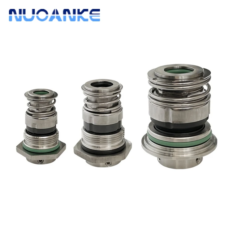
Users can choose different material for this double mechanical seal 208, matching for different liquid conditoncarbon, silicon, and tungsten carbide for this mechanical seal as seal face, if for high temerperature, we suggest to choose rubber seal viton for the rubber parts.
Lepu seal make this dual mechanical seal for many years, and offer professional suggestion when client need this grundfos seal, so we are your reliable specialist for grundfos mechanical seal.
Double mechanical seals are commonly used in the following circumstances:If the fluid and its vapors are hazardous to the operator or environment, and MUST be contained
Guangzhou Lepu machinery CO., LTD becomes one of the leading mechanical seal supplier in south of china, we focus in designing and manufacturing mechanical seal for many kinds of famous brand pumps, our mechanical seal cover many kinds of industry like food, petrol chemical, paper making, sea ship, and so on.

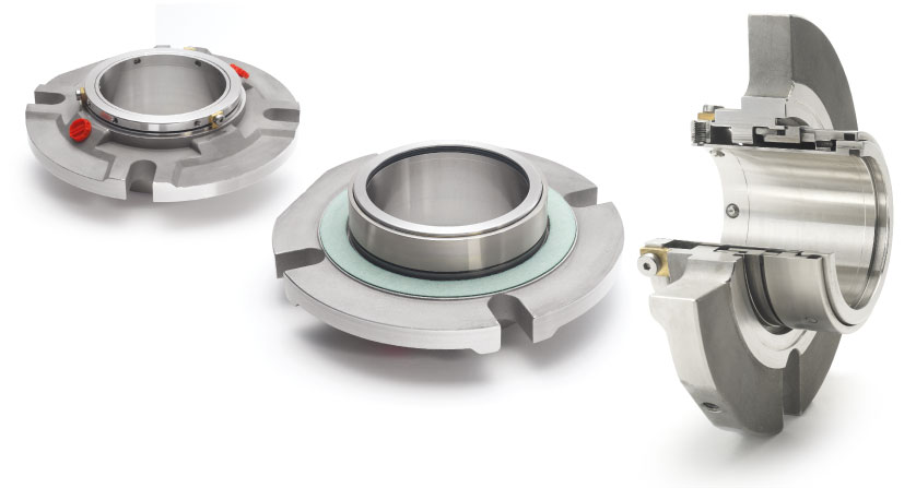
Chesterton is the world leader in design innovation of split seals. Our innovative split seals have been used to seal thousands of process-critical pieces of rotating equipment with exceptional results and many years of leak-free operations.
Chesterton was the first company to offer commercially-viable split seals for plant-wide use, which revolutionized pump sealing across industries. Since that time, we"ve launched a number of innovative split seal designs now used as a standard by companies around the globe. We offer shaft diameters ranging from 25-914 mm (1-36 in.)
A split seal has components split into two equal halves which are secured as one unit on the seal shaft. The major advantage of the split seal design is that it allows you to install the seal with no dismantling of the pump (or equipment)—an enormous time-saver! Chesterton"s split seals offer virtually leak-free performance. This leads to improved safety and environmental compliance and nearly eliminates sleeve wear, and flush water usage, among many benefits.

A mechanical seal is simply a method of containing fluid within a vessel (typically pumps, mixers, etc.) where a rotating shaft passes through a stationary housing or occasionally, where the housing rotates around the shaft.
When sealing a centrifugal pump, the challenge is to allow a rotating shaft to enter the ‘wet’ area of the pump, without allowing large volumes of pressurized fluid to escape.
To address this challenge there needs to be a seal between the shaft and the pump housing that can contain the pressure of the process being pumped and withstand the friction caused by the shaft rotating.
Before examining how mechanical seals function it is important to understand other methods of forming this seal. One such method still widely used is Gland Packing.
The stationary part of the seal is fitted to the pump housing with a static seal –this may be sealed with an o-ring or gasket clamped between the stationary part and the pump housing.
The rotary portion of the seal is sealed onto the shaft usually with an O ring. This sealing point can also be regarded as static as this part of the seal rotates with the shaft.
One part of the seal, either to static or rotary portion, is always resiliently mounted and spring loaded to accommodate any small shaft deflections, shaft movement due to bearing tolerances and out-of-perpendicular alignment due to manufacturing tolerances.
The primary seal is essentially a spring loaded vertical bearing - consisting of two extremely flat faces, one fixed, one rotating, running against each other. The seal faces are pushed together using a combination of hydraulic force from the sealed fluid and spring force from the seal design. In this way a seal is formed to prevent process leaking between the rotating (shaft) and stationary areas of the pump.
If the seal faces rotated against each other without some form of lubrication they would wear and quickly fail due to face friction and heat generation. For this reason some form of lubrication is required between the rotary and stationary seal face; this is known as the fluid film
In most mechanical seals the faces are kept lubricated by maintaining a thin film of fluid between the seal faces. This film can either come from the process fluid being pumped or from an external source.
The need for a fluid film between the faces presents a design challenge – allowing sufficient lubricant to flow between the seal faces without the seal leaking an unacceptable amount of process fluid, or allowing contaminants in between the faces that could damage the seal itself.
This is achieved by maintaining a precise gap between the faces that is large enough to allow in a small amounts of clean lubricating liquid but small enough to prevent contaminants from entering the gap between the seal faces.
The gap between the faces on a typical seal is as little as 1 micron – 75 times narrower than a human hair. Because the gap is so tiny, particles that would otherwise damage the seal faces are unable to enter, and the amount of liquid that leaks through this space is so small that it appears as vapor – around ½ a teaspoon a day on a typical application.
This micro-gap is maintained using springs and hydraulic force to push the seal faces together, while the pressure of the liquid between the faces (the fluid film) acts to push them apart.
Without the pressure pushing them apart the two seal faces would be in full contact, this is known as dry running and would lead to rapid seal failure.
Without the process pressure (and the force of the springs) pushing the faces together the seal faces would separate too far, and allow fluid to leak out.
Mechanical seal engineering focuses on increasing the longevity of the primary seal faces by ensuring a high quality of lubricating fluid, and by selecting appropriate seal face materials for the process being pumped.
When we talk about leakage we are referring to visible leakage of the seal. This is because as detailed above, a very thin fluid film holds the two seal faces apart from each other. By maintaining a micro-gap a leak path is created making it impossible for a mechanical seal to be totally leak free. What we can say, however, is that unlike gland packing, the amount of leakage on a mechanical seal should be so low as to be visually undetectable.

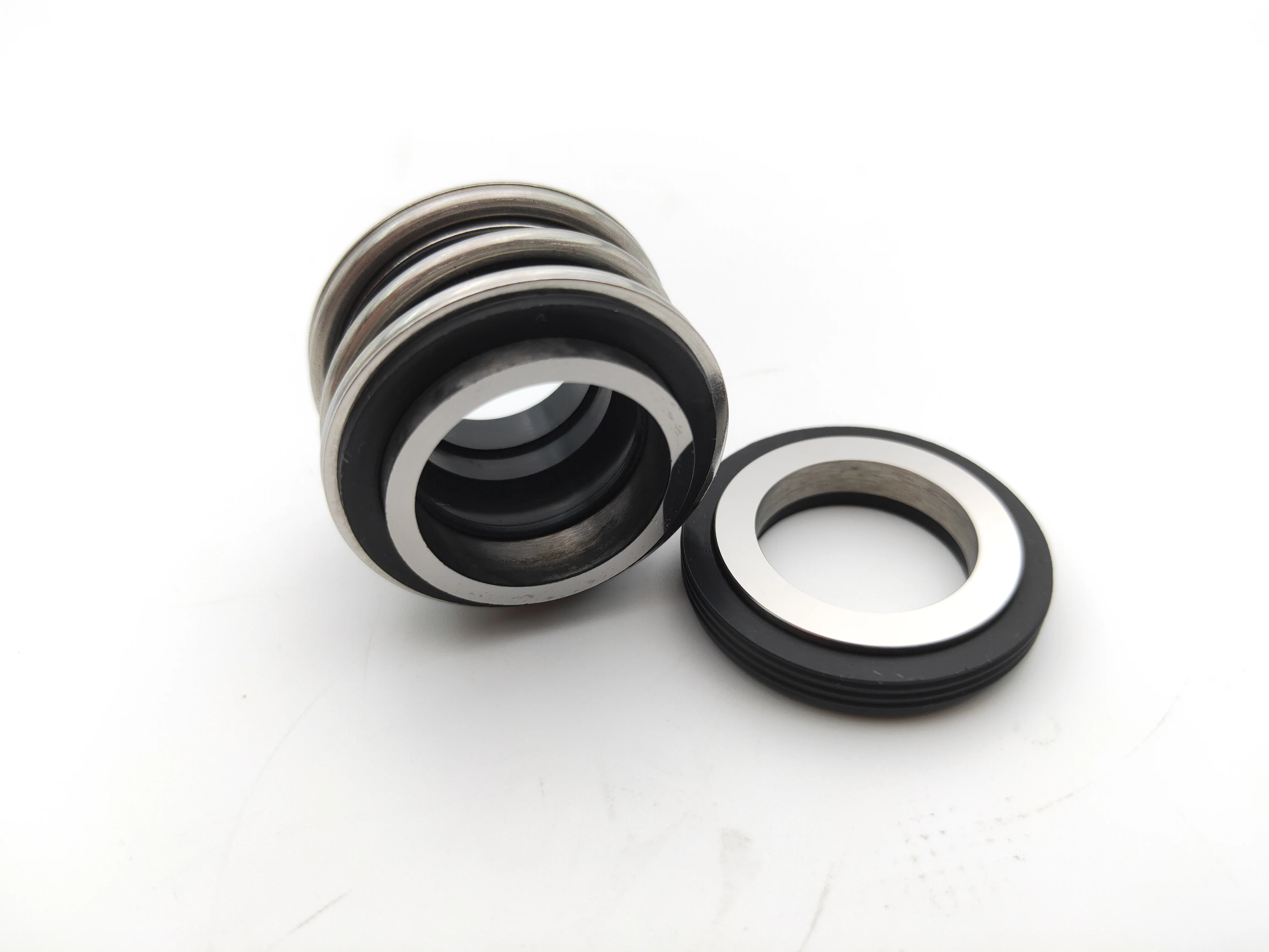
1. Take out the mechanical seal to be installed from the packing box and place it on a clean surface, protect the sealing surface, and arrange all labels and certificates for inspection;
2. Check the model, specification and material certificate of the mechanical seal, the number of parts, whether the pair of rotary face and stationary seat meet the requirements of the drawings, and whether there are identification marks of the manufacturer on the parts;
3. Check the surface quality of each part, especially whether the mechanical seal rotary face and stationary seat face are damaged or scratched. If damaged, it must be repaired or replaced. The surface of the parts must be cleaned. Especially the mechanical seal rotary face and stationary seat face can be applied by a layer of oil;
4. Check the water pressure test certificate of the graphite ring, the glass-filled PTFE ring, and the assembled rotary face and stationary seat . If there is no pressure test certificate, a water pressure test must be done before installation. The test must be in accordance with the first section of Chapter VI. Regulations;
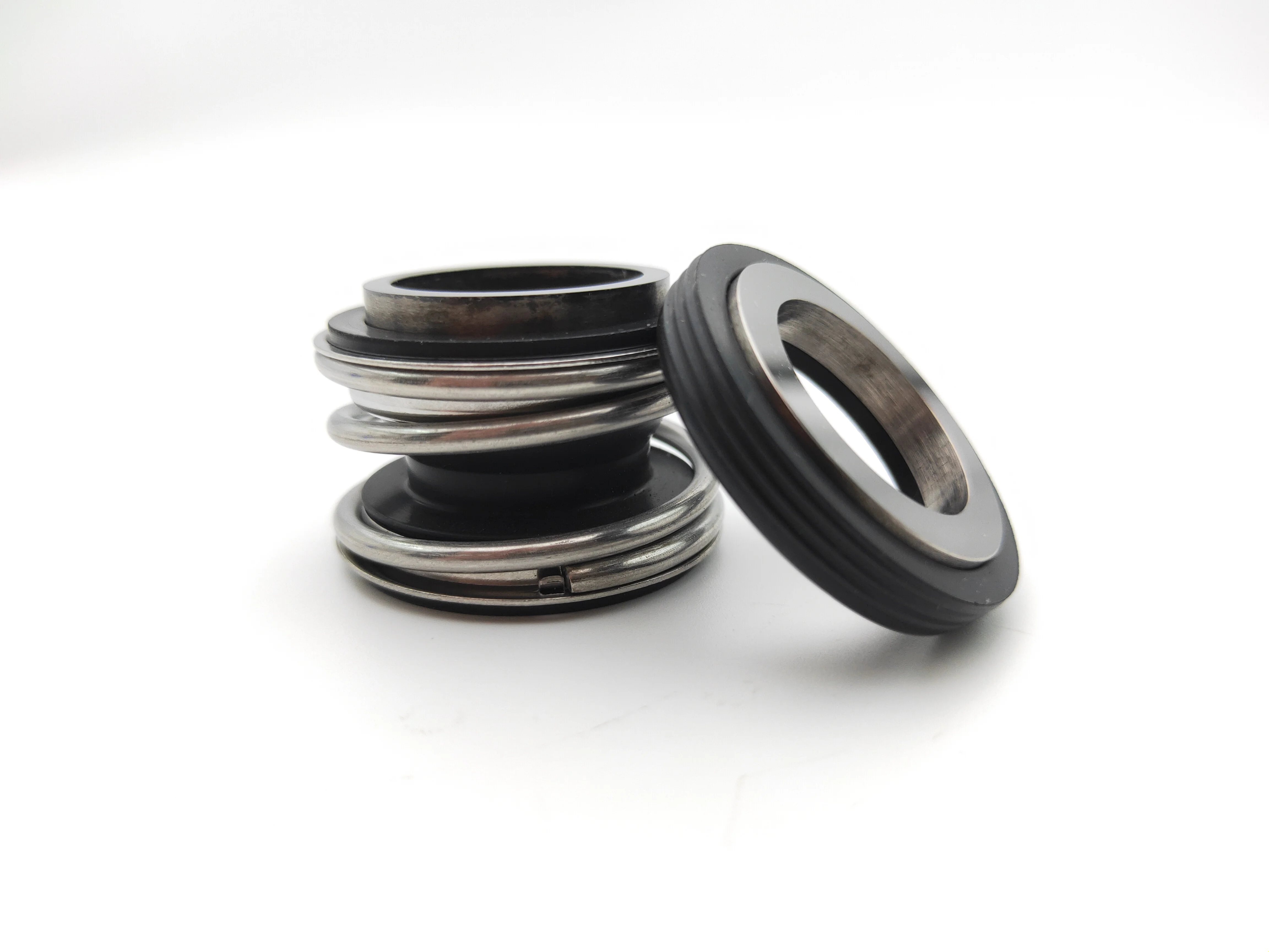
5. For mechanical seals driven by parallel coil springs, pay special attention to the direction of rotation of the spring. The direction of rotation should be the same as that of the shaft so that when we rotates it in the right direction,the spring will be the tighter and tighter .That is, in the angle from stationary seat to the rotary face according to the shaft rotation direction,a clockwise direction requires a right-handed maneuver, and vice versa.
6 Check the axical displacement, shaft radial play, related perpendicularity, concentricity, surface roughness, matching size and requirements for the shaft coupling and so on. They are all technical requirements for the host machine installed with the mechanical seal.
(1)axical displacement value:no more than 0.1mm, generally between 0.025~0.1mm. If too big, the specific pressure of the mechanical seal spring will be unstable, causing the wear or leakage of the seal face due to the vibrating of the shaft. The seal is damaged, which is more obvious in the graphite ring. In addition, because of the too big axical displacement value, partial corrosion, erosion or wearing will take place at the contacting part between the mechanical seal and the shaft (or sleeve). PTFE sealing ring are less elastic than rubber counterparts and thus more affected. Therefore, the axical displacement value needs to be changed from the original ±0.5mm to no more than 0.1mm, which can reduce the damage caused by the excessively big deviation. On the other hand, if the axical displacement value is too small, less than 0.025mm for example, it will have an adverse effect on the bearing.
In fact, the axical displacement value is also related to the shaft speed. The following figure picture 1 shows the relationship between the axical displacement and the shaft speed, which can be used for reference during installation.
(2)Allowable value of shaft radial play: Excessive shaft radial play will cause the jittering or deviation of the shaft,thus increase the seal contact surface, reduce lubricating film, and accelerate wear, which is detrimental to the sealing performance and service life of the mechanical seal. Therefore, JB4 127-85 stipulates:
(3) The verticality between the shaft and the stuffing box: no more than 0.1mm, generally 0.08mm. If the value is too big, the cover will tilt up and the mechanical seal will vibrate, and the wall surface will have uneven specific pressure and liquid film loss. Then erosion and abrasion will occur. The vibration of the mechanical seal will also wear out the driving pin, and finally make the sealing performance and service life unsatisfactory.
According to the inspection of the mechanical seal, the verticality between the shaft and the stuffing box is related to the shaft diameter and the shaft speed. It is also related to the compression method of the gasket used for sealing when the cover is installed. The use of unilateral compression will cause leakage.
(4)Concentricity between the shaft and the stuffing box of the mechanical seal : within the sliding speed V=25m/s, make sure the concentricity does not exceed 0.2mm, generally 0.125-0.2mm.(see following pictuture)
(6) Pump coupling requirements: The centering of the drive part is extremely important, because the side face runout and radial play of the coupling, the concentricity and the size of the cross-sectional gap will affect the life of the mechanical seal, thus requires checking regularly. The installation requirements of the coupling are usually stated in the instructions provided by the machine manufacturer.
The inspection required for couplingment should be carried out before the installation of all pipeline joints, otherwise, the centering work will be incomplete.
(1) Determine the installation position of the rotating parts on the shaft according to the mechanical seal assembly drawing (according to API-610, the contract materials include the operation and maintenance manual of the pump and the mechanical seal, and the separate drawing of the mechanical seal).
(2) Draw a line on the shaft to mark the position of L, if you are disassembling the machine, mark the original installation position on the shaft with a line. Then it will be easier to install the mechanical seal again.
(1) First install the anti-rotation pin1 in the pin hole of the sealing cover of the mechanical seal. Regardless of whether the vertical or horizontal anti-rotation pin is press-fitted, pay attention to the depth of the inserting, so that the prolonged pin should not touching the bottom of the groove of the stationary seat (holder)or the shaft surface.
(3) Put the stationary seal ring2 on the stationary seat3, and align the groove of the stationary seat with the anti-rotation pin1 in the cover10 , and push it evenly into the cover 10 of the mechanical seal.
(1) Place the spring adapter 4 of the mechanical seal up and flat, and then put the multiple springs 5 into the holes of the spring adapter, not skewed.
(2) Put the rotary face’s sealing ring 6 into the rotary face 7, and then put the pressure ring 8 on the rotary face of the mechanical seal . Note that the pressure ring should press the sealing ring 6.
(3)Put the pressure ring, the sealing Ring of the rotary face and the rotary face into the spring holder 4 of the mechanical seal together. Note that the groove on the outer diameter of the rotary face should be aligned with the protruding part of the spring holder.
(4)Put the spring holder together with the spring, pressure ring, rotary face and its seaingl ring on the marking position on the shaft of the mechanical seal, and then fix the rotating part on the shaft with the fixing screw 9.
Regarding the top compression amount of the spring, foreign drawings set it to be 4mm, and domestically it is generally 4~6mm, depending on the size of single spring, multiple springs and springs of the mechanical seals.
After the rotary face is installed, it must be able to move flexibly on the shaft of the mechanical seal. After the rotary face is pressed against the spring, it can automatically spring back.
(6)After the final assembling of the mechanical seal, check whether the auxiliary equipment is normal, check whether the cooling, circulation, ventilation, discharge, blocking and other pipeline joints are connected correctly. It is required that the inlet of the steam drop pipeline is at the upper part and the outlet the lower part; the cooling pipe inlet is at the lower part and the outlet at the upper part. After checking by craning, it should be light and flexible without jamming. Under normal circumstances, the radial runout of the shaft should be checked after the final assembling, and then it should be delivered to use after the static pressure test and a period of running-in.
The disassembling sequence of the mechanical seal is opposite to the installation sequence. It is strictly forbidden to use iron wares to knock it out during disassembling of the mechanical seal. It is best to use a special tool to disassemble in order. If there is dirt on the sealing element or the coagulant is dried up, the dirt should be cleaned before disassembly.


 8613371530291