
api mechanical seal plans pdf made in china

Sealing technology by EagleBurgmann is used worldwide in oil and gas industries, refineries, the petrochemical, chemical, and pharmaceutical industries, food processing, energy, water, mining, paper, aerospace, and other industries. Close to 5,800 employees provide their ideas, solutions, and commitment so that customers can rely on our sealing technology.
Clean gas despite fluctuating operating conditions. The solution for preventing seal failures due to contaminated seal gas. Combined power cycle plant, Argentina.
Mechanical seals for agitators, mixers, dryers, kneaders and other special machines. The true all-rounders when it comes to aggressive, sticky or viscous media or when solids content is high.
Standardization of seals for over forty agitators from different manufacturers in an active ingredient production to dry-running agitator seal SeccoMix.
Main catalog seal supply systems. The complete product portfolio of systems and components for cooling, flushing, pressurization and supplying liquid and gas-lubricated mechanical seals e.g., quench and thermosiphon systems, heat exchangers, barrier fluid systems, leakage monitoring and seal supply systems in accordance with API682.
As versatile as the requirements of the oil and gas industry: Sealing solutions from EagleBurgmann for water and gas injection, midstrema processes, multiphase, FPSO, Subsea, oil sands mining and LNG.
As versatile as the requirements of the power industry: So are sealing solutions from EagleBurgmann in fossil fuel-fired, nuclear and renewable energy power plants.
The innovative seal face coating for maximum operating performance of pumps, agitators and compressors in demanding applications. Features, applications and examples.
Introduction to state-of-the-art compressor seal technology, e.g. technical principle, basic seal arrangements and seal face coatings. Presentation of the complete EagleBurgmann range of dry gas seals, oil barrier seals and gas supply systems. References and services of EagleBurgmann.
Basic information about the API 682 4th edition. Contains a set of charts and summaries that gives a brief overview and represents a step-by-step method of specifying and selecting suitable EagleBurgmann sealing systems.
As versatile as the requirements of the refining industry: Sealing solutions from EagleBurgmann for distillation, cracking, gas processes, liquid and heavy hydrocarbons.
HR seals - the robust and economical solution for media with a high solids content. Advantages, products, operating conditions, references and finacial comparison.
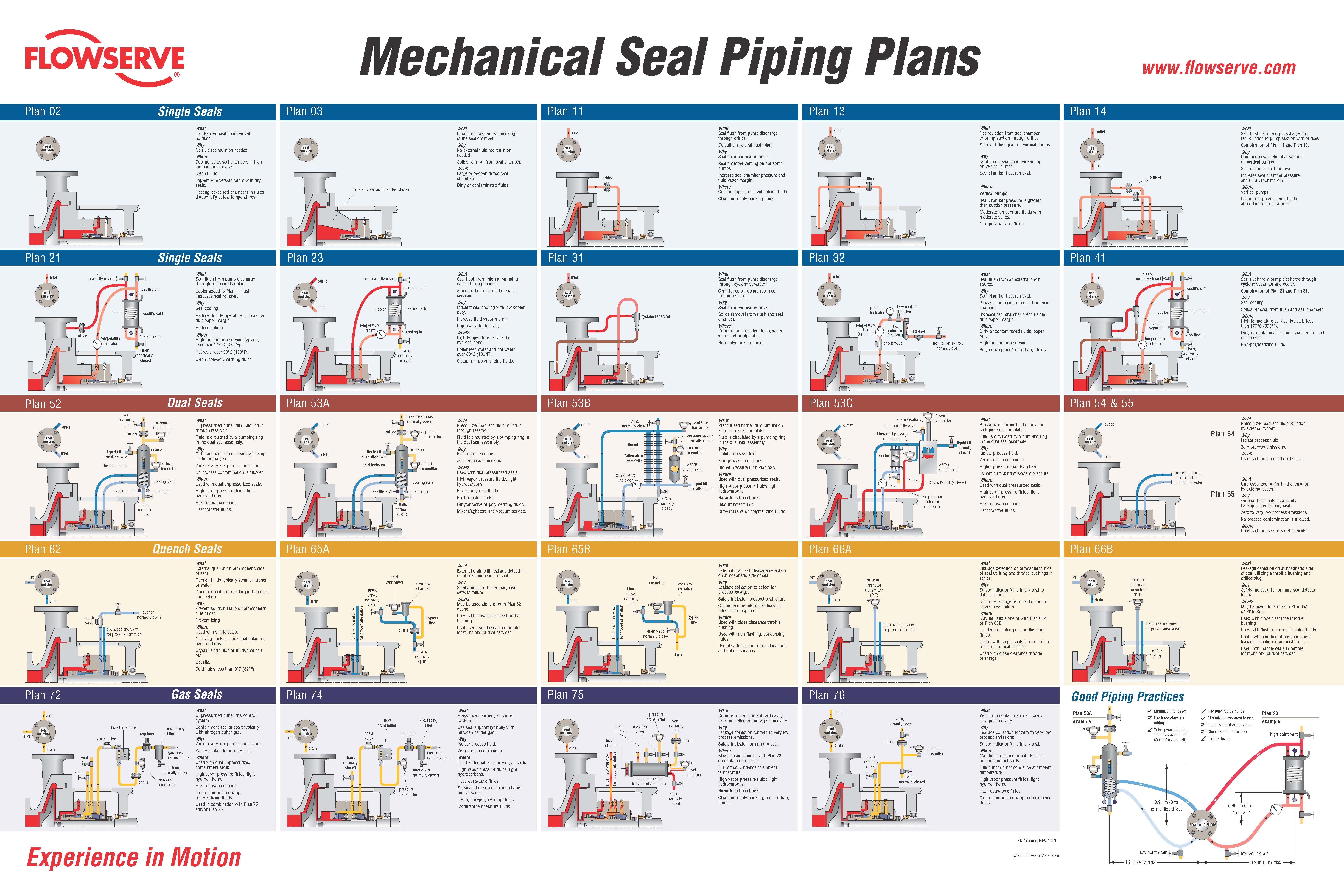
In the past there was only one Plan 53, but with the 2nd Edition of API 682 and the 1st Edition of ISO 21049 other variations of Plan 53"s were created.
The major difference in the plans is that Plan 53A uses an external reservoir, while Plans 53B and 53C run within a closed loop system with a make-up system piped to it for replenishment of the barrier fluid.
In dual pressurized sealing arrangements the inner process seal can have its own flush plan; in such applications the complete flush plan system designation should include both plans. For example, Plan 11/53A means that the inner seal has its own flush plan, Plan 11. The API/ISO default is for no separate flush plan when using any of the Plan 53"s, but this can vary with the application conditions.
With the older traditional back-to-back seal arrangement the inboard seal usually does not require a separate flush. In applications such a hydrofluoric acid, where it is both extremely hazardous and corrosive, a Plan 32 can be used in conjunction with a Plan 53. The dual pressurized face-to-back seal arrangement eliminates some of the potential problems associated with the back-to-back design. This face-to-back seal arrangement sometimes incorporates a reverse pressure capability that is not a default with the back-to-back design.
Also, face-to-back arrangements do not have a dead zone underneath the inboard seal that can become clogged by dirty process fluid and lead to seal hang-up. However, the face-to-back arrangement is not a cure-all. With the product on the seal O.D. and with it being used on API pumps that still incorporate throat bushings, it is advantageous to provide a flush for the inboard seal on a number of applications.
Abrasives can accumulate in the more closed API type seal chambers compared to the newer generation chemical duty pumps with large cylindrical bore or tapered bore chambers. The use of a Plan 11 or similar bypass type flush for the inner seal has advantages. It can help keep the seal chamber clean. It also has an improved overall heat transfer setup versus just using a Plan 53 system alone.
In comparison to a Plan 54, Plans 53A/B/C are usually less complex and less expensive. With Plans 53A/B/C, both the inner and the outer seals are lubricated by the barrier fluid, which can be selected for optimum seal performance. Plans 53A/B/C are usually selected for dirty, abrasive, or polymerizing process services which might be difficult to seal directly with single seals or with dual unpressurized seals using a Plan 52. There will always be some leakage of the barrier fluid into the process with any pressurized system.
With some of the Plan 53 systems the volume of barrier fluid is limited, especially compared to a Plan 54 system. Venting of the seal chamber is essential for all Plan 53"s where vapor locking can if vapor bubbles collect near the pumping ring or in the piping.
Plan 53A uses an external reservoir to provide barrier fluid for a pressurized dual seal arrangement. Reservoir pressure is produced by a gas, usually nitrogen, at a pressure greater than the maximum process pressure being sealed. The gas pressure is regulated by a system that is outside the schematic of the piping plan. Circulation of the barrier fluid is maintained by an internal pumping ring.
Like Plan 52 reservoirs, cooling is accomplished internal coil of tubing to remove the heat. Also like Plan 52 reservoirs, the volume of barrier liquid can vary from two gallons to 5+ gallons, where API and ISO standards specify 3-gal and 5-gal, depending upon the shaft diameter.
For non-API specifications, smaller reservoirs - typically 2-gal - are often used, especially at ambient pumping temperatures. Pressure alarms, pressure gages and level switches are typically standard equipment and are required by API 682/ISO 21049.
The usual guideline for Plan 53 barrier pressures is that they be a minimum of 20-psi to 50-psi above the maximum process pressure seen by the seal. Barrier pressure is normally supplied by a plant wide distribution system. Nitrogen bottles should not be used as they require a lot of attention and maintenance.
API 682/ISO 21049 recommends that the system be limited to 150-psig due to gas entrainment into the barrier fluid. Field experience has shown that with the proper barrier fluid, Plan 53A systems can be used up to 300-psig if the temperature is controlled to less than 250-deg F. A variation to this would be to use an accumulator to eliminate gas entrainment.
Installation should be limited to a single seal installation even on between bearing pumps. Therefore for a large number of installations, Plan 53A can be more expensive than Plan 53B or 53C.
Flow in the circulating system is usually induced by an internal pumping device. The make up system can be configured a number of ways based upon the customer"s preference, ranging from a simple hand pump to an elaborate pumping system feeding multiple pumps/seals.
API 682, 3rd edition does not provide guidelines for sizing the accumulator of Plan 53B, but the total fluid volume of the system should be about the same as the volume of a 53A system.
The finite volume of the accumulator requires a designed pressure operating range between refills (in excess of that required for a Plan 53A) and this must be built into the pressure rating of the seals.
Plan 53C is a variation of Plan 53B that uses a piston accumulator to track the pressure of the seal chamber. In Plan 53C, the piston accumulator has a reference line from the seal chamber to the bottom of the accumulator. There are differences in diameter of the internal piston so that a higher pressure is generated on the top half, which in turn is piped to the circuit loop into and out of the seal chamber.
The advantages and disadvantages are the same as the Plan 53B system. Additionally, the disadvantage of this system is that pressure spikes or pressure drops in the process pressure will vary the pressure on the outer seal that may create a temporary leakage condition. Also, tracking pressures can always be subject to delays that can cause a temporary loss of positive pressure differential across the inboard seal.
PHOTO : https://www.eagleburgmann.com/media/literature-competences-products-solutions/division-mechanical-seals/competences/brochure-barrier-buffer-media-for-mechanical-seals

Thermal transient analysis using finite element models used to determine allowable casing temperature rise and assure mechanical reliability. Hydraulic designs developed using dynamic flow models assure stable performance with consistent, high efficiency levels.
The Model 3600 can be sealed either by soft packing or mechanical seals. Seal chambers meet API-610 / ISO 13709 dimensional requirements, and accept a wide range of cartridge type mechanical seals, including API 682 / ISO 21049. Both seal chambers and stuffing boxes can be furnished with cooling jackets.


 8613371530291