
api mechanical seal plans pdf brands
To keep mechanical seal systems functioning as long as possible, we recommend using standardized seal piping plans. Detailed API seal piping plans ensure minimal seal face wear by maintaining the optimal seal chamber environment.
Since they were first formulated, seal piping plans have been maintained and remodeled by the American Petroleum Institute (API). Current plans are based on API 682 and are sorted numerically. In some cases, designated letters are also used to differentiate between plans.
A sealing system, consisting of a mechanical seal and an associated supply system that is balanced by individual applications, is the utmost guarantee for a reliable sealing point and uninterrupted pump service. The performance of the seal is greatly influenced by the environment around the seal faces, making the provision of suitable, clean fluids as well as a moderate temperature an essential topic.
This guiding booklet provides a condensed overview of all piping plans established by the API 682 4th edition guidelines. Each illustrated piping plan is briefly described, and a recommendation that considers the media characteristics in terms of the relevant application and corresponding configurations is given to help you reliably select your sealing system. Furthermore, the content of this booklet has been enriched by providing clues – so-called ‘remarks and checkpoints’ – where EagleBurgmann shares the experiences gained from multiple equipped plants.
Several factors play a major role when choosing the product, the product type, the materials used and how it is operated: process conditions at the sealing location, operating conditions and the medium to be sealed.
No matter what requirements our customers have, EagleBurgmann understands how these factors affect functionality and economic viability, and they translate this expertise into outstanding long-term, reliable sealing solutions. EagleBurgmann has all the expertise needed to manage and support the entire development, life and service cycle of its sealing solutions.
EagleBurgmann offers customers the widest product portfolio of seals and seal supply systems according to API 682 4th edition. The configurations listed for each individual piping plan are to be understood as recommendations including possible utilizations which may also be applied.
EagleBurgmann is one of the internationally leading companies for industrial sealing technology. Their products are used wherever safety and reliability are important: in the oil and gas industry, refining technology, the petrochemical, chemical and pharmaceutical industries, food processing, power, water, mining, pulp & paper and many others. More than 6,000 employees contribute their ideas, solutions and commitment towards ensuring that customers all over the world can rely on their seals and services. More than 21,000 EagleBurgmann API-seals and systems are installed world-wide.
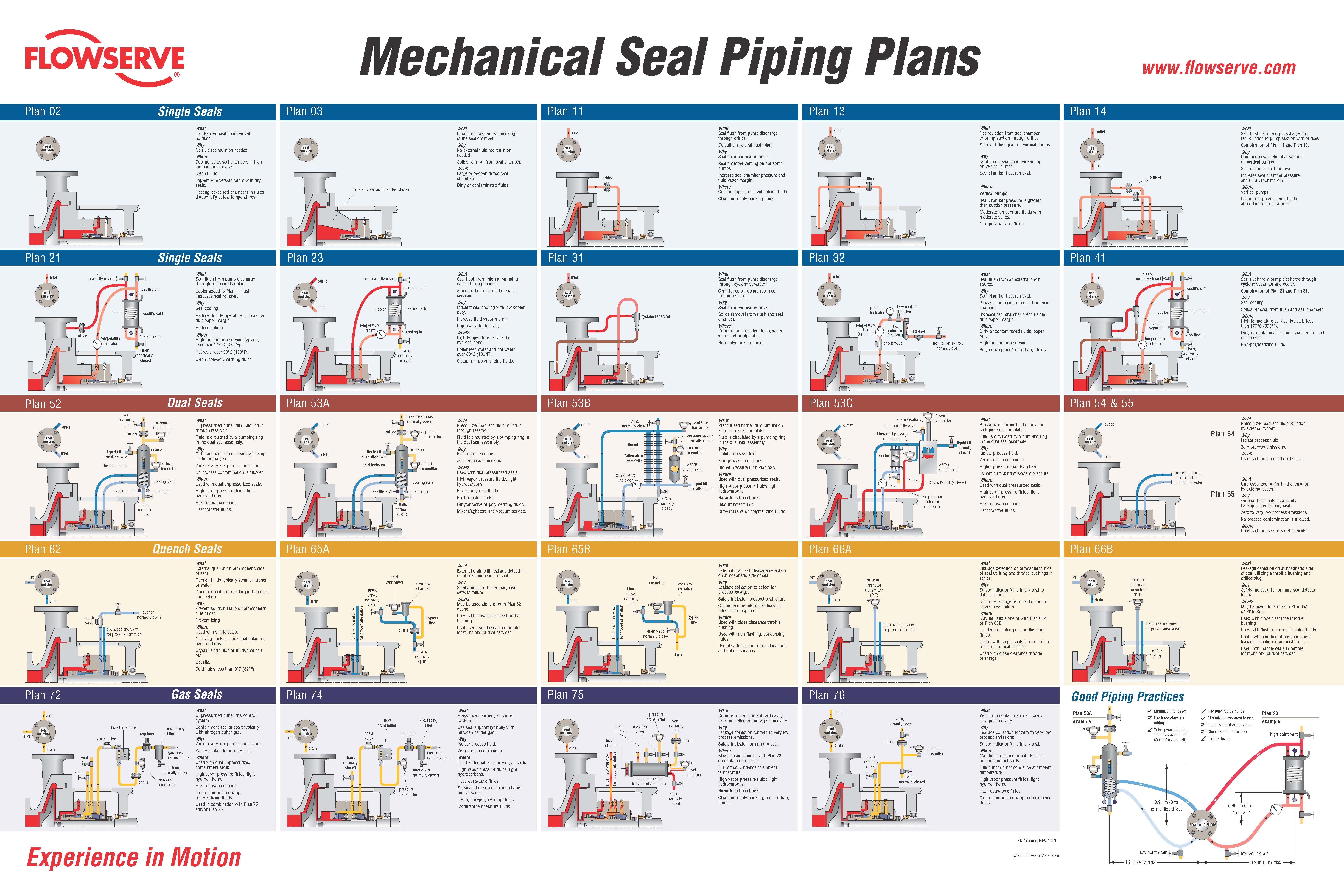
Description: Plan 01 is an internal recirculation from the pump discharge area of the pump into the seal chamber, similar to a Plan 11 but with no exposed piping. Advantages: No product contamination and no external piping, which is advantageous on highly viscous fluids at lower temperatures to minimize the risk of freezing that can occur with exposed piping. General: This flush plan should only be used for clean products as dirty products can clog the internal line. Not recommended on vertical pumps.
Description: Plan 02 is a non-circulating flush plan where adequate vapor suppression can be assured. Advantages: Solids are not continually introduced into the seal chamber, no external hardware is required, and natural venting occurs when used with a tapered bore seal chamber. General: Ideal with large bore/tapered bore ANSI/ASME B73.1 or specialised ISO 3069 seal chambers or with hot process pumps utilizing a cooling jacket. On the latter services, a Plan 62 with steam can also provide some additional cooling.
Description: Plan 11 is the most common flush plan in use today. This plan takes fluid from the pump discharge (or from an intermediate stage) through an orifice(s) and directs it to the seal chamber to provide cooling and lubrication to the seal faces. Advantages: No product contamination and piping is simple. General: If the seal is setup with a Distributed or Extended flush, the effectiveness of the system will be improved.
Description: Plan 12 is similar to Plan 11, except that a strainer or filter is added to the flush line. Advantages: No product contamination and solids are removed from the flush stream keeping the seal clean. General: If the seal is setup with a Distributed or Extended flush, the effectiveness of the system will be improved. This plan should be equipped with a differential pressure indicator or alarm to alert the user that the filter or strainer is clogged.
Description: In a Plan 13 the flow exits the seal chamber and is routed back to pump suction. Advantages: With a Plan 13 it is possible to increase or decrease seal chamber pressure with proper sizing of the orifice and throat bushing clearance. General: Typically Plan 13 is used on vertical turbine pumps since they have the discharge at the top of the pump where the seal is located. Because of the difference in flow patterns, Plan 13 is not as efficient in removing heat as a Plan 11 and thus requires a higher flow rate.
Description: Plan 14 is a combination of Plans 11 and 13. Flush is taken off of pump discharge, sent to the seal chamber, and piped back to pump suction. Advantages: Cooling can be optimized with the flush directed at the seal faces. Plan allows for automatic venting of the seal chamber. General: Often used on vertical pumps to provide adequate flow and vapor pressure margin independent of throat bushing design.
Description: Plan 21 is a cooled version of Plan 11. The product from pump discharge is directed through an orifice, then to a heat exchanger to lower the temperature before being introduced into the seal chamber. Advantages: Process fluid cools and lubricates the seal, therefore no dilution of process stream. Cooling improves lubricity and reduces the possibility of vaporization in the seal chamber.
Description: Plan 23 is a closed loop system using a pumping ring to circulate product through a heat exchanger and back to the seal chamber. Advantages: More efficient than a Plan 21 and less chance of heat exchanger fouling. Reduced temperature improves lubricity and improves vapor pressure margin.
Description: Plan 31 is variation of Plan 11, where an abrasive separator is added to the flush line. In this plan, the product is introduced to the abrasive separator from the discharge of the pump. Advantages: Unlike a strainer or filter, the abrasive separator does not require cleaning. Solids are removed from the flush stream keeping the seal clean. General: This plan should be used for services containing solids that have a specific gravity at least twice that of the process fluid. Typically the separator requires a minimum pressure differential of 15 psi (1 bar) to operate properly. High pressure differentials may require the addition of an orifice upstream of the cyclone.
Description: Plan 32 uses a flush stream brought in from an external source to the seal. This plan is almost always used in conjunction with a close clearance throat bushing. Advantages: The external flush fluid, when selected properly, can result in vastly extended seal life. General: When an outside flush source is used, concerns regarding product dilution and/or economics must be considered by the user.
Description: Plan 41 is a combination of Plan 21 and Plan 31. In Plan 41, product from pump discharge is rst put through an abrasive separator and then to the heat exchanger before being introduced to the seal chamber.
Advantages: Solids are removed and product temperature is reduced to enhance the seals environment. General: Plan 41 is typically used on hot services with solids; however, depending on the temperature of the process, operating costs can be high.
Description: Plan 52 uses an external reservoir to provide buffer fluid for the outer seal of an unpressurised dual seal arrangement. Advantages: In comparison to single seals, dual unpressurised seals can provide reduced net leakage rates as well as redundancy in the event of failure. General: Cooling coils in the reservoir are available for removing heat from the buffer fluid.
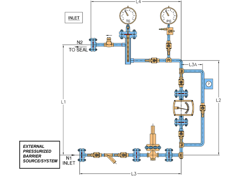
Description: Plan 53A uses an external reservoir to provide barrier fluid for a pressurised dual seal arrangement. Reservoir pressure is produced by a gas, usually nitrogen. Flow is induced by a pumping ring. Advantages: Reservoir size can be optimized dependent on flow rate. Wear particles settle to bottom of reservoir and dont get recirculated. General: Heat is dissipated by reservoir cooling coils. Barrier fluid is subject to gas entrainment at pressures/ temperatures above 300 psi (21 barg).
Description: Plan 53B previously termed 53 Modified uses an accumulator to isolate the pressurising gas from the barrier fluid. A heat exchanger is included in the circulation loop to cool the barrier fluid. Flow is induced by a pumping ring. Advantages: Should the loop be contaminated for any reason, the contamination is contained within the closed circuit. The make-up system can supply barrier fluid to multiple dual pressurised sealing systems. General: The bladder accumulator isolates the pressurising gas from the barrier fluid to prevent gas entrainment. The heat exchanger can be water cooled, finned tubing, or an air-cooled unit based upon the system heat load.
Description: Plan 53C uses a piston accumulator to provide pressure to the system. It uses a reference line from the seal chamber to provide a constant pressure differential over the chambers pressure. A water- or air-cooled heat exchanger provides for barrier fluid cooling. Flow is induced by a pumping ring. Advantages: Provides a tracking system to maintain barrier pressure above seal chamber pressure. General: The heat exchanger can be water-cooled, finned tubing, or an air-cooled unit based upon the system heat load. The reference line to the accumulator must be tolerant of process contamination without plugging.PRV
Description: Plan 54 utilizes an external source to provide a clean pressurised barrier fluid to a dual pressurised seal. Advantages: Can provide pressurised flow to multiple seal installations to reduce costs. Positively eliminates fugitive emissions to atmosphere. General: Plan 54 systems can be custom engineered to suit application requirements. Systems can range from the direct connection from other process streams to complex API 614 systems.
Description: Plan 62 is a common plan to improve the environment on the atmospheric side of single seals by quenching with steam, nitrogen or water. Advantages: Plan 62 is a low cost alternative to tandem seals. The quench prevents or retards product crystallization or coking. Quenches can also provide some cooling. General: Typical applications; steam quenches on hot services to retard coking, nitrogen quenches on cold or cryogenic service to prevent icing, or water quench to prevent crystallization or accumulation of product on the atmosphere side of the seal.
Description: Plan 65 is a liquid leakage detection plan normally used for single seals. It utilizes a level switch on a reservoir to set off an alarm when excess leakage is detected. Advantages: Provides an alarmed indication of excessive seal leakage that can shutdown equipment if necessary. General: The system includes a loop to by-pass the orifice to prevent high pressure on the atmospheric side of the seal. The gland throttle bushing design should be inline with the fluids properties.
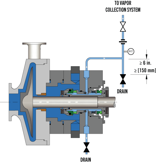
Description: Plan 72 for secondary containment uses an external low pressure buffer gas, usually nitrogen, regulated by a control panel that injects it into the outer seal cavity. Advantages: Introduction of a buffer gas like nitrogen reduces fugitive emissions, prevents icing on cold applications, and provides for some cooling to the outboard seal. General: Plan 72 is normally used with Plan 75 for primary seal leakage that is condensing, or with Plan 76 for non-condensing leakage.
Description: Plan 74 provides a pressurised gas, typically nitrogen, to dual gas seals through the use of a control panel that removes moisture, filters the gas, and regulates the barrier pressure. Advantages: Lower costs and maintenance than systems used on dual pressurised liquid systems. Leakage to atmosphere is an inert gas. General: The barrier gas is usually a pressurised nitrogen line. For higher pressure applications the system pressure can be supplemented with a gas pressure booster/amplifier.
Description: Plan 75 is a collection system used with secondary containment seals for process fluid that will condense at lower temperatures or is always in a liquid state. Advantages: The collection reservoir contains a pressure gauge and a high pressure switch to indicate a build up in pressure from excessive primary seal leakage or failure. General: Plan 75 can be used in conjunction with a gas purge from Plan 72. Typically contacting secondary containment seals are used with this plan.
Description: Plan 76 is a system to divert non-condensing primary seal leakage to a flare or vapor recovery system. Advantages: Lower initial and maintenance costs than dual unpressurised seals using a Plan 52. General: Plan 76 can be used in conjunction with a gas purge from Plan 72. Can be used with contacting or non-contacting containment seals.
API Standard 682, titled "Pumps - Shaft Sealing Systems for Centrifugal and Rotary Pumps," is the American Petroleum Institute (API) standard for end-face mechanical seals.centrifugal pumps. It is based on the combined knowledge and experience of seal manufacturers, engineering companies, and end users. API 682 is primarily intended for use in the petroleum, natural gas and chemical industries, but is often referenced for other types of equipment and industries.
By the late 1980s, mechanical seals had been accepted as the preferred method for sealing rotating pumps for many years. However, mechanical seal standards were generally buried in other standards such as DIN 24960, ANSI B73, and API 610. All of these standards were primarily pump standards and any references to seals were directed at how mechanical seals would interact with pumps.
API 610 is the API standard about centrifugal pumps and is primarily intended for use in the petroleum, natural gas and chemical industries. Although the 1st through 7th Editions of API 610 included specifications for mechanical seals, beginning with the 8th Edition, API 610 defers to API 682 for seal specifications.
In the late 1980s a group of refinery equipment engineers and managers began to compare sealing solutions in refinery applications. This group, led by V. R. Dodd of Chevron, came up with a general plan and the American Petroleum Institute (API) agreed to establish a standard for mechanical seals: API 682. A Task Force was formed in 1990 and the first meeting was held in January 1991. This Task Force was composed of fourteen members from various refineries, seal and pump manufacturers. API 682, First Edition, was published in October 1994.
One interesting aspect of API 682 is that it includes a strong set of defaults. That is, unless the user indicates otherwise, API 682 makes default choices for specifics such as:
Some statements within API 682 are normative, that is, required, whereas others are informative, that is, descriptive but not required. In particular, many of the illustrations are informative. This distinction has not always been apparent to the reader.
The first edition of API 682 was entirely new although parts of it were extracted from the pump standard API 610 and existing API standard paragraphs.
Although this mission statement no longer appears in the standard, it remains the basic principle driving the work of the API 682 Task Force and its relevance remains the same for the 4th Edition as it did for the 1st.
In addition to providing requirements for mechanical seals, the 1st Edition of API 682 also provided a guide on how to select the correct seal for a number of common refinery applications. In order to provide this seal selection guide, it was necessary to categorize applications into a number of services:
Prior to API 682, 1st Edition, multiple seals were designated as being either “tandem” or “double” seals; however, advances in seal design had rendered these classic terms obsolete. As a result, there was some confusion on how multiple seals were designated. The task force decided to use a more descriptive designation and chose to define dual seal arrangements. A dual seal would be two sets of sealing faces used in the same seal chamber. The fluid between these two sets of sealing faces could be either pressurized or unpressurized. Three standard arrangements were defined:
After having defined the services, seal types, and seal arrangements, a series of flowcharts were created to help in selecting a seal type, special materials or design requirements, and supporting piping plans.
API 682 seals were to have a high probability of three years of reliable service. In order to prove this, seal performance testing on process fluids under representative pressures and temperatures was required. These performance tests are called “Qualification Tests”.
The general idea of the qualification test was to prove that the design was sound. The goal of the qualification test was to simulate a long-term steady state run followed by a process upset. The simulated process upset consisted of pressure changes, temperature changes and included loss of flush. The results of these tests were made available to the purchaser for evaluation. There was no acceptance criteria presented in API 682 1st Edition.
In addition to the qualification test of the design, every API 682 seal, whether new or repaired, is to be pressure tested with air before being shipped to the end user.
One of the major criticisms of API 682 1st Edition was that all the seals were “heavy duty” and therefore expensive with no alternatives for easy services. To some degree, this was intentional and was done in order to reduce inventory, promote familiarity with a limited number of seal types and to increase reliability. Another criticism of API 682 1st Edition was that it considered only API 610 pumps and only refinery applications. The chemical and petrochemical industries routinely use ASME pumps in addition to API 610 pumps. Broadening the scope of pumps covered by API 682 would allow standardized seals to be applied in a greater number of industries.
In 2nd Edition, the organization of API 682 was changed to conform to ISO standards: This reorganization means that there is no simple cross reference guide between 1st edition and 2nd edition paragraph numbers.
The 2nd Edition introduced the concept of seal categories. A seal category describes the type of pump into which the seal will be installed, the operating window, the design features, and the testing and documentation requirements. There are three categories designated as Category 1, 2, or 3.
Category 1 seals are intended for non-API-610 pumps. This category is applicable for temperatures between –40°F and 500°F (-40°C and 260°C) and pressures to 315 PSI (22 bar).
Category 2 seal are intended for API-610 This category is applicable for temperatures between –40°F and 750°F (-40°C and 400°C) and pressures to 615 PSI (42 bar).
Category 3 seals are essentially the original seals of 1st Edition and are also intended for API-610 pumps. Category 3 seals are intended for the most demanding applications. This category is applicable for temperatures between –40°F and 750°F (-40°C and 400°C) and pressures to 615 PSI (42 bar). Design features include a distributed flush and floating throttle bushing for single seals. Additional documentation must be also provided.
Containment seals are the outer seal of Arrangement 2. In the 2nd Edition, containment seals can be used with a liquid buffer fluid, a gas buffer fluid or without a buffer fluid. In the case of a dry running containment seal, the containment seal will be exposed primarily to buffer gas or vaporized process fluid. Such containment seals must therefore be designed for continuous dry running while meeting the reliability goals of the standard. Dry running containment seals may be either contacting or non-contacting.
Non-contacting inner seals are also introduced for Arrangement 2. One of the primary targets for non-contacting inner seals is in flashing hydrocarbon services. In some of these services, it is impossible to obtain adequate vapor margins to prevent flashing of the fluid in the seal chamber. This seal will be used with a dry running containment seal and the leakage past the inner seal will be piped to a vapor recovery system.
The other new seal type introduced in 2nd Edition was the dry running gas seal used in Arrangement 3. This seal is designed to run on a gas barrier fluid such as nitrogen.
Several new piping plans were introduced in the 2nd Edition. These included additional options for dual pressurized liquid seals as well as new piping plans to support containment seals and dual pressurized gas seals.
One of the strengths of the 1st Edition was to provide qualification tests in which seal vendors would be required to prove the suitability of their seals for a given service. The 2nd Edition expanded on these requirements by adding new tests for containment seals and dual gas seals as well as defining acceptance criteria for all tests.
For all practical purposes, API 682 3rd Edition is the same as 2nd Edition. The completed 2nd Edition was submitted to the ISO Organization for approval as their ISO 21049. At the time, API and ISO had an agreement to jointly issue standards. The ISO Organization made slight editorial changes to 2nd Edition, including correcting typographical errors and unit conversions. Therefore, API had to re-issue a corrected 2nd edition but choose to label it as 3rd edition. API 682 3rd Edition was published in September 2004.
API and ISO no longer have the agreement to jointly issue standards. The 2004 issue of ISO 21049 is the only issue and plans to update it are unknown.
Seal Configuration refers to the orientation of the seal components in an assembly. In previous editions, orientations were defined as face-to-back, back-to-back, and face-to-face and these terms are carried over into the 4th Edition. In 4th Edition, any orientation (face to back, back to back, face to face) can be used in a dual seal provided that the design features are appropriate to the functionality of that particular arrangement.
Fourth Edition added additional specifications for clearances, placed these requirements in the form of tables and noted that seal components are not to be considered as “shaft catchers” to restrict shaft movement. The minimum clearances specified apply only to equipment within the scope of the standard. Equipment outside that scope, such as non-cartridge seals, older pumps, non-API 610 pumps and certain severe services, might benefit from larger clearances.
Before API 682, API 610 (the pump standard) used a simple seal code to specify seals. API 682 attempted to use a more comprehensive seal code; however, that code changed with every edition of API 682. The 4th Edition code, described in Annex D, is probably the best to date and includes some concepts and codes from the historical API 610 seal code.
Annex G provides illustrations and a short tutorial about each piping plan. As has been the case for every edition, changes were made to the standard piping plans. In particular, the piping plans now default to using transmitters with local indicators as part of the instrumentation.
API standards are reviewed every five years and re-issued every ten years. A new Taskforce for API 682 was formed in 2017 and preparations for 5th Edition are underway.
Buck, G. S., Huebner, M. B, Thorp, J. M., and Fernandez, C. L. “Advances in Mechanical Sealing – An Introduction to API-682 Second Edition”, Texas A&M Turbomachinery Symposium, 2003.
API Standard 682, Second Edition, 2001, “Pumps – Shaft Sealing Systems for Centrifugal and Rotary Pumps,” American Petroleum Institute, Washington, D.C.
API Standard 682, Third Edition, 2004, “Pumps – Shaft Sealing Systems for Centrifugal and Rotary Pumps,” American Petroleum Institute, Washington, D.C.
API Standard 682, Fourth Edition, 2014, “Pumps – Shaft Sealing Systems for Centrifugal and Rotary Pumps,” American Petroleum Institute, Washington, D.C.


 8613371530291