
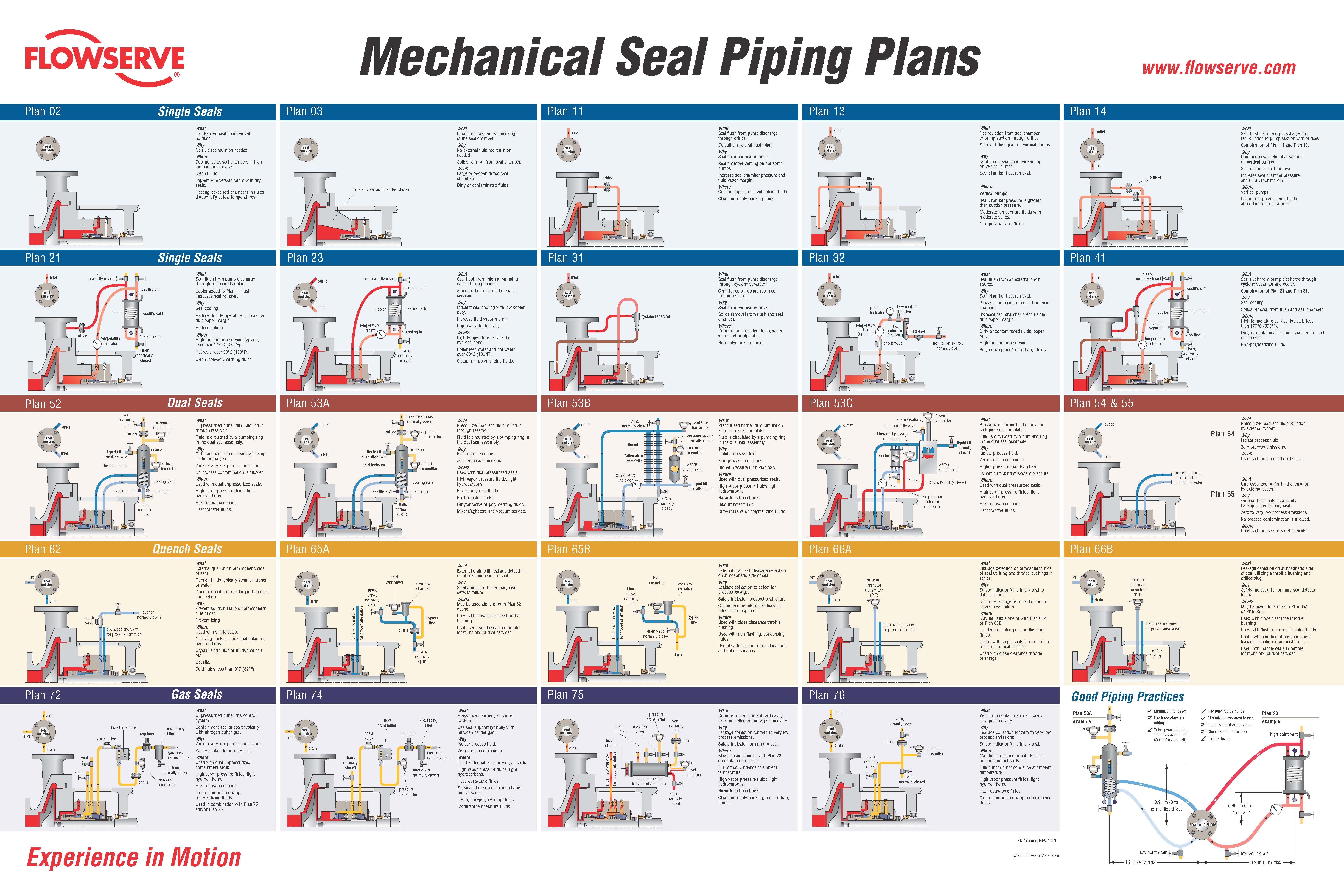
api mechanical seal plans pdf price
Pressurised barrier fluid circulation in outboard seal of dual seal configuration through a seal support system. Circulation is maintained by using pumping ring in running condition and with thermosyphon effect in stand still condition.
In the past there was only one Plan 53, but with the 2nd Edition of API 682 and the 1st Edition of ISO 21049 other variations of Plan 53"s were created.
The major difference in the plans is that Plan 53A uses an external reservoir, while Plans 53B and 53C run within a closed loop system with a make-up system piped to it for replenishment of the barrier fluid.
In dual pressurized sealing arrangements the inner process seal can have its own flush plan; in such applications the complete flush plan system designation should include both plans. For example, Plan 11/53A means that the inner seal has its own flush plan, Plan 11. The API/ISO default is for no separate flush plan when using any of the Plan 53"s, but this can vary with the application conditions.
With the older traditional back-to-back seal arrangement the inboard seal usually does not require a separate flush. In applications such a hydrofluoric acid, where it is both extremely hazardous and corrosive, a Plan 32 can be used in conjunction with a Plan 53. The dual pressurized face-to-back seal arrangement eliminates some of the potential problems associated with the back-to-back design. This face-to-back seal arrangement sometimes incorporates a reverse pressure capability that is not a default with the back-to-back design.
Also, face-to-back arrangements do not have a dead zone underneath the inboard seal that can become clogged by dirty process fluid and lead to seal hang-up. However, the face-to-back arrangement is not a cure-all. With the product on the seal O.D. and with it being used on API pumps that still incorporate throat bushings, it is advantageous to provide a flush for the inboard seal on a number of applications.
Abrasives can accumulate in the more closed API type seal chambers compared to the newer generation chemical duty pumps with large cylindrical bore or tapered bore chambers. The use of a Plan 11 or similar bypass type flush for the inner seal has advantages. It can help keep the seal chamber clean. It also has an improved overall heat transfer setup versus just using a Plan 53 system alone.
In comparison to a Plan 54, Plans 53A/B/C are usually less complex and less expensive. With Plans 53A/B/C, both the inner and the outer seals are lubricated by the barrier fluid, which can be selected for optimum seal performance. Plans 53A/B/C are usually selected for dirty, abrasive, or polymerizing process services which might be difficult to seal directly with single seals or with dual unpressurized seals using a Plan 52. There will always be some leakage of the barrier fluid into the process with any pressurized system.
With some of the Plan 53 systems the volume of barrier fluid is limited, especially compared to a Plan 54 system. Venting of the seal chamber is essential for all Plan 53"s where vapor locking can if vapor bubbles collect near the pumping ring or in the piping.
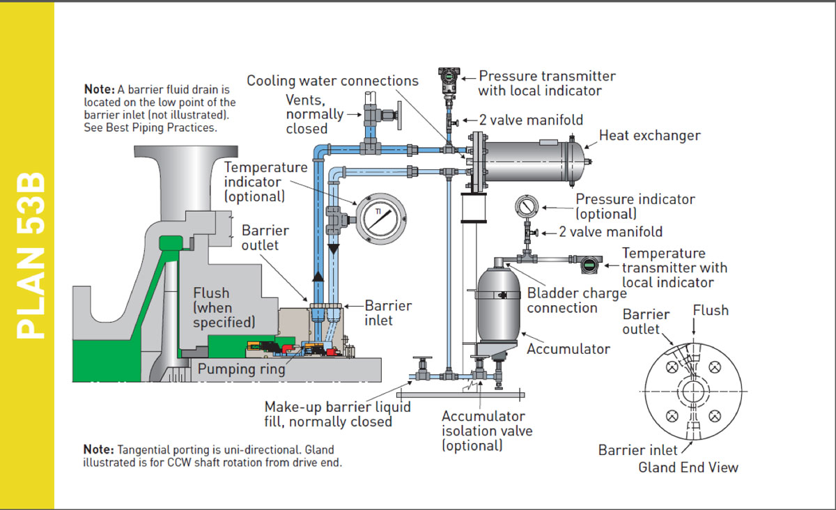
Plan 53A uses an external reservoir to provide barrier fluid for a pressurized dual seal arrangement. Reservoir pressure is produced by a gas, usually nitrogen, at a pressure greater than the maximum process pressure being sealed. The gas pressure is regulated by a system that is outside the schematic of the piping plan. Circulation of the barrier fluid is maintained by an internal pumping ring.
Like Plan 52 reservoirs, cooling is accomplished internal coil of tubing to remove the heat. Also like Plan 52 reservoirs, the volume of barrier liquid can vary from two gallons to 5+ gallons, where API and ISO standards specify 3-gal and 5-gal, depending upon the shaft diameter.
For non-API specifications, smaller reservoirs - typically 2-gal - are often used, especially at ambient pumping temperatures. Pressure alarms, pressure gages and level switches are typically standard equipment and are required by API 682/ISO 21049.
The usual guideline for Plan 53 barrier pressures is that they be a minimum of 20-psi to 50-psi above the maximum process pressure seen by the seal. Barrier pressure is normally supplied by a plant wide distribution system. Nitrogen bottles should not be used as they require a lot of attention and maintenance.
API 682/ISO 21049 recommends that the system be limited to 150-psig due to gas entrainment into the barrier fluid. Field experience has shown that with the proper barrier fluid, Plan 53A systems can be used up to 300-psig if the temperature is controlled to less than 250-deg F. A variation to this would be to use an accumulator to eliminate gas entrainment.
Installation should be limited to a single seal installation even on between bearing pumps. Therefore for a large number of installations, Plan 53A can be more expensive than Plan 53B or 53C.
Flow in the circulating system is usually induced by an internal pumping device. The make up system can be configured a number of ways based upon the customer"s preference, ranging from a simple hand pump to an elaborate pumping system feeding multiple pumps/seals.
API 682, 3rd edition does not provide guidelines for sizing the accumulator of Plan 53B, but the total fluid volume of the system should be about the same as the volume of a 53A system.
The finite volume of the accumulator requires a designed pressure operating range between refills (in excess of that required for a Plan 53A) and this must be built into the pressure rating of the seals.
Plan 53C is a variation of Plan 53B that uses a piston accumulator to track the pressure of the seal chamber. In Plan 53C, the piston accumulator has a reference line from the seal chamber to the bottom of the accumulator. There are differences in diameter of the internal piston so that a higher pressure is generated on the top half, which in turn is piped to the circuit loop into and out of the seal chamber.
The advantages and disadvantages are the same as the Plan 53B system. Additionally, the disadvantage of this system is that pressure spikes or pressure drops in the process pressure will vary the pressure on the outer seal that may create a temporary leakage condition. Also, tracking pressures can always be subject to delays that can cause a temporary loss of positive pressure differential across the inboard seal.
PHOTO : https://www.eagleburgmann.com/media/literature-competences-products-solutions/division-mechanical-seals/competences/brochure-barrier-buffer-media-for-mechanical-seals

Mechanical seals are a great cause of concern and failures in many operating plants. This is especially true of systems that are pumping or compressing dirty fluids. Some examples include bottoms pumps, sulfur pumps, or equipment that is handling abrasive or challenging process media. Mechanical seals are often redesigned, replaced and repaired simply because of the challenging conditions these seals face during operation. This has continually led to excessive costs in terms of repair or redesign, not to mention production loss and cost associated on a critical unspared asset.
While seals have to be properly selected and designed for the application during the project’s engineering stages, it is equally critical to select the right and most cost-effective seal plan to help support the seal’s operating environment. The seal flush plan is as equally critical and perhaps more so to help establish a reliable operating mechanical seal. API Standard 682 from the American Petroleum Institute provides various seal plan configurations, their advantages and disadvantages and a good description of each of the plans. To gain an in-depth understanding of the various types of applications and plans available for selection, refer to API 682. In addition, a lot of seal vendors publish handy booklets that contain good, brief and quick references and explanations of the different API seal plans.
This particular article looks at API Plan 53B and how paying careful attention to some aspects of this plan can ensure a proper and reliable running seal in many applications. Of course, the mechanical seal should be correctly and most optimally designed for the particular application at hand.
Figure 1 shows a basic overview of what a 53B seal flush plan looks like. It is a pressurized flush plan that gets used with a dual seal (i.e., two seals) configuration. The accumulator contains a bladder that is pre-charged at a certain calculated bladder pre-charge pressure value through the bladder charge connection shown in Figure 1. Next, the barrier fluid, which can be royal purple or another process compatible based media, is injected into the system at a certain calculated hydraulic charge pressure through the make-up barrier fill or a similar port provided on the piping setup. The idea is that when the seal fails (leaks are more than expected since all seals leak to some extent), then the barrier fluid, being at a higher pressure, will push the leakage back into the process rather than letting the process media leak outside into the ambient. This helps prevent environmental release and avoids wastage of costly process media to the atmosphere. It is quite clear based on this that such plans are best suited for applications that are toxic and hazardous and where negligible leakage is allowed into the atmosphere due to such concerns. Consider reading ample literature available from various sources to gain a deeper understanding of this particular plan.
One of the key advantages of this particular plan is the cost associated with implementing it in a given plant compared to other similar options (i.e., Plan 54 or others). However, it is imperative to realize that the reliability of a 53B plan and the mechanical seal it supports is highly dependent on the plant operator who maintains this and checks on the system on a regular basis. While a number of seal failures can be attributed to incorrect designs or other issues, equally, if not more, causes can be attributed to how a plan 53B is operated and maintained on a running asset.
Here are a few important points that should be considered while working with any plan 53B in a maintenance and operating organization.It is important to vent a 53B through the appropriate vent points provided to ensure there is no vapor entrapment prior to seal start-up. Attention should be paid to horizontal versus vertical heat exchangers provided on the system. Based on experience, it is easier to vent out vertical heat exchanger configurations versus horizontal systems. However, horizontal systems are provided or should be provided with block valves to help ensure proper venting.
In colder climates where a plan 53B is installed outside, the system should be properly heat traced and winterized. This includes the seal flush piping, the accumulator and the exchangers. The accumulator contains a nitrogen bladder with a pre-charge pressure as previously indicated. Fluctuations in the ambient temperature can have a dramatic effect on system pressure and lead to seal failures and loss of seal system reliability.
Operations should confirm and check with engineering that the right calculated values are provided for the pre-charge pressure for the bladder and also the hydraulic system charge pressures. These are quite critical to ensuring system and seal reliability. Any discrepancies in these calculated values can risk reverse pressurization (i.e., seal reversal) and subsequent failure of the sealing system. It is important to note that some plants consider playing around with the pre-charge and hydraulic charge values to buy more time between system failure and low-level alarm of the barrier fluid so the operator has sufficient time to fill and make up the loss of barrier in the system. However, experience has shown the best way to address this issue is to procure accumulators of higher volumes to provide for this as opposed to modifying pressures to buy more volume in the system. The latter seems to have much smaller effects compared to sizing the accumulator correctly in the first place. Also, if consideration is being given to changing pre-charge and hydraulic pressures, this should be in discussions with the original equipment manufacturer (OEM) seal vendor since excess pressures on a given seal can compromise and affect seal leakage rates, thus reducing the time and volume present in the system.
It is equally important that the operator only charge (i.e., make-up fill with hand-pump) the system when the low-level alarm pressure is initiated. Charging the system at every minor occasion when the barrier pressure and level drops is not warranted. This, on the contrary, will lead to a poor seal system and seal reliability as a result of multiple pressure charging in short intervals.
Operations should keep a log of charging frequencies, depending on the low-level alarm. This, along with visual inspections, can provide a good clue to seal failures and acceptable leakage rates. The question most often asked by an operator is: What is considered an acceptable leakage? While engineering, along with the seal OEM, can provide acceptable leakage rates, to get a very good measure of seal reliability, the operator can keep an eye out for the frequency of fill and also, if correctly done, the volume filled during the initial fill cycle.
Since the pump throat bushing controls the stuffing box environment, it would be beneficial to incorporate the throat bushing on the seal cartridge itself to help with maintenance, as opposed to locating it within the pump. This holds true not just for the 53B seal plan, but for others as well.
Having a temperature gauge located on both the inlet and outlet of the seal helps in establishing a temperature gradient between the seal’s in and out flow. A difference of around 20 to 30 degrees C is acceptable; any more delta T changes can point to possible issues with the seal, cooling water, or other variables. This can help the operator make on-site decisions to engage or escalate the issue to engineering in the event of a potential problem.
While there are many individual experiences connected to running a 53B seal flush plan, these important points most certainly can help the operator make an informed decision to help seal reliability and mean time between failures (MTBF) in a running plant. Engineering should perform a detailed root cause analysis on complex seal issues and provide the appropriate solutions sought to address repeated failures. This will help the plant’s bottom line: Cost and Revenue.


 8613371530291