
api 682 mechanical seal made in china

YALAN research and development center is located in city of Hefei, the captial of Anhui Province, China. It has 10 very experienced senior engineers working as a team for developing new mechanical seal solutions and provide technical support to the production factory of YALAN Seals.
The team has accomplished a total amount of over 3,600 models of mechanical seals and won 28 patents and invention. The search center of YALAN Seals is also named as one of the national high tech enterprises and provincial mechanical seal design and development technical center.

Cyclone separators of the ZY203 range are used to clean mainly aqueous liquids containing dirt and solids (e.g. in circulation systems of sewage, sludge or pipeline pumps). The best possible filtration efficiency is achieved when the specific weight of the solids is much higher than that of the carrier liquid (recommended by API 682 4th edition: at least double), and when the differential pressure is as large as possible within the permissible pressure range (min. 1.7 bar in accordance with API 682). The viscosity of the medium is also a factor that needs to be taken into account.

6 US GAL API682 Plan52 Plan53A Mechanical Seal Support System performs all basic function of a buffer/barrier system for the operation of double seals:

Mechanical seals became the dominant sealing technology in refineries and chemical plants in the 1980s, causing the American Petroleum Institute (API) to establish a committee whose sole focus was to write standards for these components. The first edition, API 682 Shaft Sealing Systems for Centrifugal and Rotary Pumps was published in 1994 with this mission statement, “This standard is designed to default to the equipment types most commonly supplied that have a high probability of meeting the objective of at least three years of uninterrupted service while complying with emissions regulations." (API Standard 682, First Edition, 1994 “Shaft Sealing Systems for Centrifugal and Rotary Pumps,” American Petroleum Institute, Washington, D.C.). Notably, the standard includes recommendations that unless otherwise specified, default to technology that has proven to be safe and reliable. Currently in its fourth edition, API 682 continues to offer guidance based on process service for both mechanical seals and their support systems.
While much of the standard is focused on mechanical seals, a significant portion is devoted to seal support systems, as they are a critical component to the proper functioning of the seal and pump system. As a manufacturer of seal support systems, Swagelok Company and our sales and service centers have implemented the best practices of API 682 4th Edition. In this blog post, we will explain what some of those best practices are, and how implementing recommendations from the standard in the construction and design of your seal support systems can help you meet your goals of increasing reliability and safety while reducing costs.
Before we discuss best practices, let’s look at the functions of seal support systems. These systems are designed for a specific mechanical seal and set of process conditions. Typically, they supply either a gas or a liquid to the mechanical seal to regulate the environment in which the seal operates, protecting rotating equipment from damage.
Throughout API 682 4th Edition, there are references to reducing the number of connections in seal support systems. Whether welded pipe or tubing is selected for the system, threaded systems are discouraged. Every connection can be viewed as a potential leak point and possible reliability risk in hydrocarbon pumping applications. Leaks on seal support systems near pumps can cause asset damage, increased downtime, environmental issues, and safety risks.
In the past, many seal support systems were constructed out of pipe due to piping being historically preferred. More recently, seal manufacturers, end users, and pump OEMS have implemented tubing as a connection solution in seal support systems due to its long history of successful use in critical applications throughout the industrial world. As rotating equipment expert Heinz Bloch noted in a recent Hydrocarbon Processing article, “[the] American Petroleum Institute Standard 682 (API 682) began to endorse the use of tubing for some seal piping plans. Regrettably, tradition-bound purchasers still opt for hard pipe; we are asking them to reconsider. API 682 (4th Edition) now specifies seal support system connections almost interchangeably.” (Bloch, Heinz P., Consider Stainless Steel Tubing for Mechanical Seal Connections, Hydrocarbon Processing, March, 2018)
Tubing can be utilized to reduce the number of connections by bending lines and appropriately using adapter fittings. Often, the only needed connections are those at the seal and the sealing system. Since tubing is annealed, bending the tubing work hardens the metal, increasing the strength of the tube at the bend. Innovative connection technologies such as flange adapters and extended male connectors further reduce the number of connections from threaded ports on the seal and seal pots by eliminating the need for multiple fittings. The use of tubing provides further financial benefit when we examine the MRO costs of the pump, seal, and support system. During maintenance operations where “piping” around pumps is reworked, the use of tubing eliminates the need for costly on-site welding and can be installed quickly to reduce downtime.
Seal support systems are critical to the proper operation of the seal and pump, and as such, require regular visual inspection. Making the job of visual inspection simple promotes system reliability and safety. When designing seal support systems, there are several best practice design principles to consider once the piping plan and general arrangement have been selected.
Mechanical seals are often damaged when pumps are started and stopped, sometimes as the result of improper seal support system operation. If the design of the seal support system facilitates proper operation, common mistakes when commissioning pumps can be avoided.
In API 682 4th Edition, a Plan 32 is shown as multiple instruments and components installed on either piping or tubing. While functionally correct, this design provides the operator little information regarding the operation of the system, what information is important, and why it is important. If the system is located down next to the seal on a pump, the operator now needs to walk back to the pump and bend down to read instrument information. Creating even small obstacles for operators increases the risk that trouble signals will be missed and reduces reliability. An intuitive solution is to arrange these components on a panel.
Additionally, API 682 supports these design considerations. It states: “All controls and instruments shall be located and arranged to permit easy visibility by the operators, as well as accessibility for tests, adjustments, and maintenance” (9.1.5) (API Standard 682, Fourth Edition, 2014 “Shaft Sealing Systems for Centrifugal and Rotary Pumps,” American Petroleum Institute, Washington, D.C)
Lastly, panels can include part numbering information, flow path indication, and operator instructions. These improvements help ensure safe and reliable startup and shutdown of pumps and seal support systems.
While correct operation of the seal support system is a high priority, consideration should also be given to designing systems that are easy to maintain. Seal support systems contain commonly serviced items such as flow meters, strainers, and other visual instruments. Preventative maintenance (PM) on these systems should be simple and safe for operators. If strainers are not conveniently positioned and available for blowdown, it is unlikely that proper PM will be performed at recommended intervals.
API 682 4th Edition also recommends block-bleed configurations for all gauges. If systems are not designed with this feature, it is likely that as gauges fail, operators will be left without critical information until the next turnaround or project when the pump and support system can be decommissioned and the gauge replaced.
Lastly, there are a wide variety of tubing connections and design options that allow for every serviceable component on a seal support system to be easily removed and replaced while continuing to operate the system. For seal pots, the 4th Edition stipulates “Local operation, venting, filling, and draining shall be accomplished from grade. Unless otherwise specified, systems that require the use of a ladder or step or that require climbing on the baseplate or piping are not acceptable” (8.1.8) (API Standard 682, Fourth Edition, 2014 “Shaft Sealing Systems for Centrifugal and Rotary Pumps,” American Petroleum Institute, Washington, D.C.). Many plants have older seal pots with just a pipe plug at the top. Having operators climb a ladder to top-off the pot can expose them to process vapors and is a generally unsafe practice. Designing Plan 52s or Plan 53s with fill systems such as the one shown below is a simple design consideration and best practice that promotes safe maintenance.
Implementing these basic best practice design principles for mechanical seal support system increases reliability and reduces costs. To recap how you can realize better results with your systems:Consider using tubing instead of welded pipe to reduce installation and maintenance costs. This will also promote reliability through the reduction of potential leak points.
Bringing pumps offline to fix minor instrumentation issues or fill seal pots should not be acceptable. Locating these systems on panels, with proper labeling and designing for easy maintenance reduces the chance for operator error which can damage seals.
Seal failures and the associated costs of seal replacement should be of great concern to rotating equipment groups at all plants. Ensuring that the best practices and design principals of API 682 4th Edition are followed helps prevent these costs and creates a safer and more reliable operation.
Swagelok provides design and assembly of seal support systems through our network of more than 200 authorized sales and service centers. We offer configurable, local, and reliable systems that are better by design to help you reduce costs, save time, and improve safety of your rotating equipment. For additional advice on designing and installing your mechanical seal support systems, or to find the right API seal plan kits or assemblies for your applications, reach out to your local Swagelok team.

API 682 Category 1 seals specific for ASME B73.1 and ASME B73.2 and ISO 2858 enlarged-bore chemical process pumps. Within the John Crane 5600 Universal Cartridge Seal series, a fully compliant line of API 682 versions are designed and qualification-tested.
Here’s an interesting little anecdote that I was told many years ago. I may not have it quite right and, for all I know, it may not even be true, but here goes. In the 1970s, I was told that very long ago, the practice was to test pumps at 2 x MAWP. Perhaps this was because pumps are manufactured from castings. Anyway, there was a pump standards meeting (perhaps this was even an early form of an API standards meeting) and a requirement was written to hydrostatically test pumps at 1.5 x MAWP. After the meeting, the chief engineer for a major pump manufacturer was buying drinks for everyone at the bar. Surprised by his generosity, a fellow committee member remarked that the 2x hydrostatic test must have been difficult. “Not at all”, said the chief engineer, “In fact, I just increased all my pressure ratings by 33%!” That is, pumps previously rated for 600 psig MAWP but hydrostatically tested at 1200 psig could still be hydrostatically tested at 1200 psig but then rated for 800 psig MAWP!
I’ve been told that the multiplication factor for determining the hydrostatic test pressure will be changed from 1.5 to 1.3 according to the ASME Pressure Vessel Code Section VIII. Apparently this will be applied to both pumps and piping. The same multiplier will probably be used for API 682 reservoirs such as are used with Piping Plan 52 and 53. The pertinent 4th Edition clauses for reservoirs now read:
Pipe based reservoirs for API 682 sealing systems must be built entirely of piping components and ASME B31.3, “Process Piping”, (ISO 15649) is the governing standard. As far as I can tell, ASME B31.3 now requires hydrostatic testing at 1.3 x MAWP.
It should be noted that the mechanical seal is not considered to be part of the pump pressure vessel and therefore does not fall under the pressure vessel rules. Seal manufacturers have several pressure ratings for their products. API 682 recognizes a static pressure rating, a dynamic pressure rating and a hydrostatic pressure test rating (see the SealFAQs version of these definitions). Each seal OEM seems to use a different and proprietary method for determining these pressure limits.

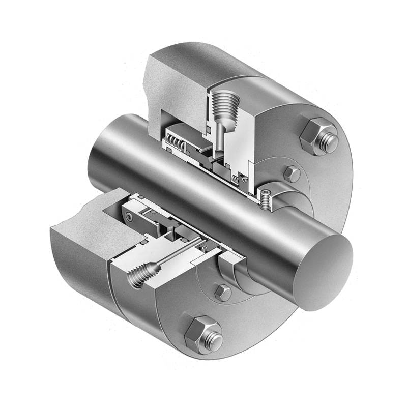
Materials used for the manufacture of mechanical seal faces. These materials must meet the tribological demands unique to mechanical seals. Industry has evolved primarily to the use of mechanical carbons and ceramics for these components. A mechanical seal (Fig. 1) is by its very nature a collection of components that are designed to control leakage of a fluid through a sealing interface. These components serve a wide variety of functions and correspondingly require a wide range of material properties. Many of these properties, such as mechanical strength, thermal conductivity, or corrosion resistance, are similar to considerations made for many other devices. Some properties, however, are unique to mechanical seals, such as coefficient of...
M.B. Huebner, Material selection for mechanical seals, in Proceedings of the 21st International Pump User’s Symposium, Turbomachinery Laboratory, Texas A&M University, College Station, Texas (2005)
Editors and AffiliationsDepartment of Mechanical Engineering and Center for Surface Engineering and Tribology, Northwestern University, Evanston, IL, USA

Sealing technology by EagleBurgmann is used worldwide in oil and gas industries, refineries, the petrochemical, chemical, and pharmaceutical industries, food processing, energy, water, mining, paper, aerospace, and other industries. Close to 5,800 employees provide their ideas, solutions, and commitment so that customers can rely on our sealing technology.


 8613371530291