
api 682 mechanical seal brands
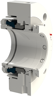
The Flexaseal Style 59A is designed specifically to conform to API 682 Category 2 Applications for Midstream and Downstream Oil and Gas Applications. Standard design features include:
The 59A is also available with contacting and noncontacting secondary sealing. The Flexaseal FC seal (Available as 59A/FC) provides decades of proven operational reliability as a contacting secondary seal. The Flexaseal FGSA (Available as 59A/FGSA) is our newest lift-off design for API applications that require a noncontacting secondary seal.
Mechanical seals became the dominant sealing technology in refineries and chemical plants in the 1980s, causing the American Petroleum Institute (API) to establish a committee whose sole focus was to write standards for these components. The first edition, API 682 Shaft Sealing Systems for Centrifugal and Rotary Pumps was published in 1994 with this mission statement, “This standard is designed to default to the equipment types most commonly supplied that have a high probability of meeting the objective of at least three years of uninterrupted service while complying with emissions regulations."Currently in its fourth edition, API 682 continues to offer guidance based on process service for both mechanical seals and their support systems.
While much of the standard is focused on mechanical seals, a significant portion is devoted to seal support systems, as they are a critical component to the proper functioning of the seal and pump system. As a manufacturer of seal support systems, Swagelok Company and our sales and service centers have implemented the best practices of API 682 4th Edition. In this blog post, we will explain what some of those best practices are, and how implementing recommendations from the standard in the construction and design of your seal support systems can help you meet your goals of increasing reliability and safety while reducing costs.
Before we discuss best practices, let’s look at the functions of seal support systems. These systems are designed for a specific mechanical seal and set of process conditions. Typically, they supply either a gas or a liquid to the mechanical seal to regulate the environment in which the seal operates, protecting rotating equipment from damage.
Throughout API 682 4th Edition, there are references to reducing the number of connections in seal support systems. Whether welded pipe or tubing is selected for the system, threaded systems are discouraged. Every connection can be viewed as a potential leak point and possible reliability risk in hydrocarbon pumping applications. Leaks on seal support systems near pumps can cause asset damage, increased downtime, environmental issues, and safety risks.
In the past, many seal support systems were constructed out of pipe due to piping being historically preferred. More recently, seal manufacturers, end users, and pump OEMS have implemented tubing as a connection solution in seal support systems due to its long history of successful use in critical applications throughout the industrial world. As rotating equipment expert Heinz Bloch noted in a recent Hydrocarbon Processing article, “[the] American Petroleum Institute Standard 682 (API 682) began to endorse the use of tubing for some seal piping plans. Regrettably, tradition-bound purchasers still opt for hard pipe; we are asking them to reconsider. API 682 (4th Edition) now specifies seal support system connections almost interchangeably.”
Tubing can be utilized to reduce the number of connections by bending lines and appropriately using adapter fittings. Often, the only needed connections are those at the seal and the sealing system. Since tubing is annealed, bending the tubing work hardens the metal, increasing the strength of the tube at the bend. Innovative connection technologies such as flange adapters and extended male connectors further reduce the number of connections from threaded ports on the seal and seal pots by eliminating the need for multiple fittings. The use of tubing provides further financial benefit when we examine the MRO costs of the pump, seal, and support system. During maintenance operations where “piping” around pumps is reworked, the use of tubing eliminates the need for costly on-site welding and can be installed quickly to reduce downtime.
Seal support systems are critical to the proper operation of the seal and pump, and as such, require regular visual inspection. Making the job of visual inspection simple promotes system reliability and safety. When designing seal support systems, there are several best practice design principles to consider once the piping plan and general arrangement have been selected.
Mechanical seals are often damaged when pumps are started and stopped, sometimes as the result of improper seal support system operation. If the design of the seal support system facilitates proper operation, common mistakes when commissioning pumps can be avoided.
Additionally, API 682 supports these design considerations. It states: “All controls and instruments shall be located and arranged to permit easy visibility by the operators, as well as accessibility for tests, adjustments, and maintenance” (9.1.5)
Lastly, panels can include part numbering information, flow path indication, and operator instructions. These improvements help ensure safe and reliable startup and shutdown of pumps and seal support systems.
API 682 4th Edition also recommends block-bleed configurations for all gauges. If systems are not designed with this feature, it is likely that as gauges fail, operators will be left without critical information until the next turnaround or project when the pump and support system can be decommissioned and the gauge replaced.
Lastly, there are a wide variety of tubing connections and design options that allow for every serviceable component on a seal support system to be easily removed and replaced while continuing to operate the system. For seal pots, the 4thEdition stipulates “Local operation, venting, filling, and draining shall be accomplished from grade. Unless otherwise specified, systems that require the use of a ladder or step or that require climbing on the baseplate or piping are not acceptable” (8.1.8) .
Implementing these basic best practice design principles for mechanical seal support system increases reliability and reduces costs. To recap how you can realize better results with your systems:
Bringing pumps offline to fix minor instrumentation issues or fill seal pots should not be acceptable. Locating these systems on panels, with proper labeling and designing for easy maintenance reduces the chance for operator error which can damage seals.
Seal failures and the associated costs of seal replacement should be of great concern to rotating equipment groups at all plants. Ensuring that the best practices and design principals of API 682 4th Edition are followed helps prevent these costs and creates a safer and more reliable operation.
Swagelok provides design and assembly of seal support systems through our network of more than 200 authorized sales and service centers. We offer configurable, local, and reliable systems that are better by design to help you reduce costs, save time, and improve safety of your rotating equipment.
For additional advice on designing and installing your mechanical seal support systems, or to find the right API seal plan kits or assemblies for your applications, reach out to your local Swagelok team.

A sealing system, consisting of a mechanical seal and an associated supply system that is balanced by individual applications, is the utmost guarantee for a reliable sealing point and uninterrupted pump service. The performance of the seal is greatly influenced by the environment around the seal faces, making the provision of suitable, clean fluids as well as a moderate temperature an essential topic.
This guiding booklet provides a condensed overview of all piping plans established by the API 682 4th edition guidelines. Each illustrated piping plan is briefly described, and a recommendation that considers the media characteristics in terms of the relevant application and corresponding configurations is given to help you reliably select your sealing system. Furthermore, the content of this booklet has been enriched by providing clues – so-called ‘remarks and checkpoints’ – where EagleBurgmann shares the experiences gained from multiple equipped plants.
Several factors play a major role when choosing the product, the product type, the materials used and how it is operated: process conditions at the sealing location, operating conditions and the medium to be sealed.
No matter what requirements our customers have, EagleBurgmann understands how these factors affect functionality and economic viability, and they translate this expertise into outstanding long-term, reliable sealing solutions. EagleBurgmann has all the expertise needed to manage and support the entire development, life and service cycle of its sealing solutions.
EagleBurgmann offers customers the widest product portfolio of seals and seal supply systems according to API 682 4th edition. The configurations listed for each individual piping plan are to be understood as recommendations including possible utilizations which may also be applied.
EagleBurgmann is one of the internationally leading companies for industrial sealing technology. Their products are used wherever safety and reliability are important: in the oil and gas industry, refining technology, the petrochemical, chemical and pharmaceutical industries, food processing, power, water, mining, pulp & paper and many others. More than 6,000 employees contribute their ideas, solutions and commitment towards ensuring that customers all over the world can rely on their seals and services. More than 21,000 EagleBurgmann API-seals and systems are installed world-wide.

After more than five years of planning, the American Petroleum Institute (API) is preparing to release the 4th edition of API Standard 682 (ISO 21049:2011). The API 682 standard, which dates back to 1994 and is formally known as Shaft Sealing Systems for Centrifugal and Rotary Pumps, offers specifications and best practices for mechanical seals and systems to pump end users.
The standard’s latest edition began to take shape in 2006, when API formed a 4th edition task force to respond to end users’ questions and comments about previous editions. The task force soon realized that major changes, including reorganization and editing, would be necessary. While addressing every aspect of the resulting 4th edition (which is more than 250 pages long) would be impossible, this article summarizes the standard’s main points.
Those who use API 682 should understand the standard’s scope and remember that the standard does not include specifications for equipment outside that scope, such as engineered seals or mixers. Another important but often misunderstood point is that API 682’s figures are illustrative and not normative in their entirety.
For example, one of API 682’s figures shows a fixed throttle bushing combined with a rotating Type A seal, but seal manufacturers do not always have to combine these two components. The standard provides normative details in clauses and tables to help purchasers distinguish between requirements and suggestions.
The 4th edition continues to divide seals into three categories, three types and three arrangements. For all practical purposes, seal manufacturers can combine a seal’s component parts into nearly any orientation or configuration. Each orientation and configuration has advantages and disadvantages with respect to certain applications, performance and system disturbances.
Before the 4th edition, API 682 did not specify a minimum clearance between the inside diameter of a stationary seal part and the outside diameter of a rotating seal part. The 4th edition specifies this minimum clearance—typically the clearance between the sleeve and the mating ring. The specified clearances are representative of standard clearances that end users have used for decades. End users should not consider seal components to be “shaft catchers” to restrict shaft movement. The minimum clearance specified in API 682 also applies only to equipment within the standard’s scope. Equipment outside that scope, such as non-cartridge seals, older pumps, non-API 610 pumps and certain severe services, might benefit from larger clearances.
The new standard also updates the default bushings for the gland plate for the three seal categories. Fixed throttle bushings are now the default for Category 1 only, while floating bushings are the default for Categories 2 and 3.
While the 4th edition features the recommended seal selection procedure from the standard’s first three editions, it adds an alternative selection method in Annex A. Proposed by task force member Michael Goodrich, this alternative method recommends using material data sheet information to select a sealing arrangement.
Plans 66A and 66B are new to the standard, although end users have used them previously in pipeline applications. These plans detect and restrict excessive leakage rates in case of an Arrangement 1 seal failure.
The 4th edition has revised the data sheets in Annex C extensively to make them the same for all seal categories. Only two data sheets are included in the 4th edition—one in metric units and one in U.S. customary units. The new edition also folds Annex J into Annex E.
Previous editions of API 682 required metal plugs and anaerobic sealants when shipping new or repaired cartridges. After much debate, the task force decided that threaded connection points should be protected with plastic plugs for shipment. These plastic plugs should be red and have center tabs that operators can pull easily to distinguish the plugs from metal plugs. Shippers should also attach yellow warning tags to the plugs to indicate that end users need to remove the plugs before operation.
Although tutorial notes are scattered throughout API 682, this edition expands the tutorial section, Annex F, from seven pages to 42 pages. The expanded annex includes illustrative calculations. In particular, users interested in systems such as Plan 53B will find Annex F to be useful.
The 4th edition of API 682 is the product of more than 20 years of discussion, debate, usage and peer review. It includes a strong set of defaults and is by far the best and most logical starting point for mechanical seal and systems use. Equipment operators should take the time to familiarize themselves with API 682 to get the most out of this comprehensive standard.

API 682 has created definitions for many of the common features and attributes of mechanical seals and systems. When new concepts are introduced or options are added to the standard, they must be captured in the definitions.
Type A is a balanced, cartridge mounted seal which utilized elastomeric secondary seals. Type B is a cartridge mounted seal which utilizes the flexible metal bellows and elastomeric secondary seals. The Type C Seal is a cartridge mounted high temperature bellows seals which utilizes flexible graphite secondary seals. Other requirements such as face materials and elastomers are tied to these definitions.
This article contains excerpts from the paper, "Advancements in mechanical sealing -- API 682 Fourth Edition" at the 2013 International Pump Users Symposium held at Houston, Texas.
The Fourth Edition of API 682 expands on these definitions slightly. Type A and B seals have historically been defined as having flexible rotating elements. This means that the springs or bellows assembly will rotate with the shaft. This was selected as the default design in the First Edition due to the high population of these designs in the refinery industry. Type C seals have historically defaulted to stationary flexible elements.

API Standard 682, titled "Pumps - Shaft Sealing Systems for Centrifugal and Rotary Pumps," is the American Petroleum Institute (API) standard for end-face mechanical seals.centrifugal pumps. It is based on the combined knowledge and experience of seal manufacturers, engineering companies, and end users. API 682 is primarily intended for use in the petroleum, natural gas and chemical industries, but is often referenced for other types of equipment and industries.
By the late 1980s, mechanical seals had been accepted as the preferred method for sealing rotating pumps for many years. However, mechanical seal standards were generally buried in other standards such as DIN 24960, ANSI B73, and API 610. All of these standards were primarily pump standards and any references to seals were directed at how mechanical seals would interact with pumps.
API 610 is the API standard about centrifugal pumps and is primarily intended for use in the petroleum, natural gas and chemical industries. Although the 1st through 7th Editions of API 610 included specifications for mechanical seals, beginning with the 8th Edition, API 610 defers to API 682 for seal specifications.
In the late 1980s a group of refinery equipment engineers and managers began to compare sealing solutions in refinery applications. This group, led by V. R. Dodd of Chevron, came up with a general plan and the American Petroleum Institute (API) agreed to establish a standard for mechanical seals: API 682. A Task Force was formed in 1990 and the first meeting was held in January 1991. This Task Force was composed of fourteen members from various refineries, seal and pump manufacturers. API 682, First Edition, was published in October 1994.
One interesting aspect of API 682 is that it includes a strong set of defaults. That is, unless the user indicates otherwise, API 682 makes default choices for specifics such as:
Some statements within API 682 are normative, that is, required, whereas others are informative, that is, descriptive but not required. In particular, many of the illustrations are informative. This distinction has not always been apparent to the reader.
The first edition of API 682 was entirely new although parts of it were extracted from the pump standard API 610 and existing API standard paragraphs.
Although this mission statement no longer appears in the standard, it remains the basic principle driving the work of the API 682 Task Force and its relevance remains the same for the 4th Edition as it did for the 1st.
In addition to providing requirements for mechanical seals, the 1st Edition of API 682 also provided a guide on how to select the correct seal for a number of common refinery applications. In order to provide this seal selection guide, it was necessary to categorize applications into a number of services:
Prior to API 682, 1st Edition, multiple seals were designated as being either “tandem” or “double” seals; however, advances in seal design had rendered these classic terms obsolete. As a result, there was some confusion on how multiple seals were designated. The task force decided to use a more descriptive designation and chose to define dual seal arrangements. A dual seal would be two sets of sealing faces used in the same seal chamber. The fluid between these two sets of sealing faces could be either pressurized or unpressurized. Three standard arrangements were defined:
After having defined the services, seal types, and seal arrangements, a series of flowcharts were created to help in selecting a seal type, special materials or design requirements, and supporting piping plans.
API 682 seals were to have a high probability of three years of reliable service. In order to prove this, seal performance testing on process fluids under representative pressures and temperatures was required. These performance tests are called “Qualification Tests”.
The general idea of the qualification test was to prove that the design was sound. The goal of the qualification test was to simulate a long-term steady state run followed by a process upset. The simulated process upset consisted of pressure changes, temperature changes and included loss of flush. The results of these tests were made available to the purchaser for evaluation. There was no acceptance criteria presented in API 682 1st Edition.
In addition to the qualification test of the design, every API 682 seal, whether new or repaired, is to be pressure tested with air before being shipped to the end user.
One of the major criticisms of API 682 1st Edition was that all the seals were “heavy duty” and therefore expensive with no alternatives for easy services. To some degree, this was intentional and was done in order to reduce inventory, promote familiarity with a limited number of seal types and to increase reliability. Another criticism of API 682 1st Edition was that it considered only API 610 pumps and only refinery applications. The chemical and petrochemical industries routinely use ASME pumps in addition to API 610 pumps. Broadening the scope of pumps covered by API 682 would allow standardized seals to be applied in a greater number of industries.
In 2nd Edition, the organization of API 682 was changed to conform to ISO standards: This reorganization means that there is no simple cross reference guide between 1st edition and 2nd edition paragraph numbers.
The 2nd Edition introduced the concept of seal categories. A seal category describes the type of pump into which the seal will be installed, the operating window, the design features, and the testing and documentation requirements. There are three categories designated as Category 1, 2, or 3.
Category 1 seals are intended for non-API-610 pumps. This category is applicable for temperatures between –40°F and 500°F (-40°C and 260°C) and pressures to 315 PSI (22 bar).
Category 2 seal are intended for API-610 This category is applicable for temperatures between –40°F and 750°F (-40°C and 400°C) and pressures to 615 PSI (42 bar).
Category 3 seals are essentially the original seals of 1st Edition and are also intended for API-610 pumps. Category 3 seals are intended for the most demanding applications. This category is applicable for temperatures between –40°F and 750°F (-40°C and 400°C) and pressures to 615 PSI (42 bar). Design features include a distributed flush and floating throttle bushing for single seals. Additional documentation must be also provided.
Containment seals are the outer seal of Arrangement 2. In the 2nd Edition, containment seals can be used with a liquid buffer fluid, a gas buffer fluid or without a buffer fluid. In the case of a dry running containment seal, the containment seal will be exposed primarily to buffer gas or vaporized process fluid. Such containment seals must therefore be designed for continuous dry running while meeting the reliability goals of the standard. Dry running containment seals may be either contacting or non-contacting.
Non-contacting inner seals are also introduced for Arrangement 2. One of the primary targets for non-contacting inner seals is in flashing hydrocarbon services. In some of these services, it is impossible to obtain adequate vapor margins to prevent flashing of the fluid in the seal chamber. This seal will be used with a dry running containment seal and the leakage past the inner seal will be piped to a vapor recovery system.
The other new seal type introduced in 2nd Edition was the dry running gas seal used in Arrangement 3. This seal is designed to run on a gas barrier fluid such as nitrogen.
Several new piping plans were introduced in the 2nd Edition. These included additional options for dual pressurized liquid seals as well as new piping plans to support containment seals and dual pressurized gas seals.
One of the strengths of the 1st Edition was to provide qualification tests in which seal vendors would be required to prove the suitability of their seals for a given service. The 2nd Edition expanded on these requirements by adding new tests for containment seals and dual gas seals as well as defining acceptance criteria for all tests.
For all practical purposes, API 682 3rd Edition is the same as 2nd Edition. The completed 2nd Edition was submitted to the ISO Organization for approval as their ISO 21049. At the time, API and ISO had an agreement to jointly issue standards. The ISO Organization made slight editorial changes to 2nd Edition, including correcting typographical errors and unit conversions. Therefore, API had to re-issue a corrected 2nd edition but choose to label it as 3rd edition. API 682 3rd Edition was published in September 2004.
API and ISO no longer have the agreement to jointly issue standards. The 2004 issue of ISO 21049 is the only issue and plans to update it are unknown.
Seal Configuration refers to the orientation of the seal components in an assembly. In previous editions, orientations were defined as face-to-back, back-to-back, and face-to-face and these terms are carried over into the 4th Edition. In 4th Edition, any orientation (face to back, back to back, face to face) can be used in a dual seal provided that the design features are appropriate to the functionality of that particular arrangement.
Fourth Edition added additional specifications for clearances, placed these requirements in the form of tables and noted that seal components are not to be considered as “shaft catchers” to restrict shaft movement. The minimum clearances specified apply only to equipment within the scope of the standard. Equipment outside that scope, such as non-cartridge seals, older pumps, non-API 610 pumps and certain severe services, might benefit from larger clearances.
Before API 682, API 610 (the pump standard) used a simple seal code to specify seals. API 682 attempted to use a more comprehensive seal code; however, that code changed with every edition of API 682. The 4th Edition code, described in Annex D, is probably the best to date and includes some concepts and codes from the historical API 610 seal code.
API standards are reviewed every five years and re-issued every ten years. A new Taskforce for API 682 was formed in 2017 and preparations for 5th Edition are underway.
Buck, G. S., Huebner, M. B, Thorp, J. M., and Fernandez, C. L. “Advances in Mechanical Sealing – An Introduction to API-682 Second Edition”, Texas A&M Turbomachinery Symposium, 2003.
API Standard 682, Second Edition, 2001, “Pumps – Shaft Sealing Systems for Centrifugal and Rotary Pumps,” American Petroleum Institute, Washington, D.C.
API Standard 682, Third Edition, 2004, “Pumps – Shaft Sealing Systems for Centrifugal and Rotary Pumps,” American Petroleum Institute, Washington, D.C.
API Standard 682, Fourth Edition, 2014, “Pumps – Shaft Sealing Systems for Centrifugal and Rotary Pumps,” American Petroleum Institute, Washington, D.C.
-1.jpg?width\u003d901\u0026name\u003dimage3%20(1)-1.jpg)
Many users do not like the strong handed approach used by API 682. However, with a little study of API 682, the user can easily learn to specify his preferences in detail using the seal data sheet.
Some statements within API 682 are normative, that is, required, whereas others are informative, that is, descriptive but not required. In particular, many of the illustrations are informative. This distinction has not always been apparent to the reader.
In spite of its strong handed approach, API 682 encourages innovative or developing technology. However, non-standard alternatives should be carefully discussed between the purchaser and seal company.
It is important to realize that API 682 is a users’ standard; it was written by and for the end users of mechanical seals and these users wanted to force changes. The result was an entirely new standard written around a limited set of seal types, arrangements and materials that were favored by the end users in refineries. These new seals were also required to be proven through a series of rigidly prescribed tests. Although everyone agreed that API 682 seals were robust and well suited to the best practices of the refining industry, cost quickly became a limiting factor to the specification. Consequently, API 682 1stEdition was not applied as extensively as had been anticipated. Subsequent editions have had an increase in the scope and also are more flexible with respect to defaults and options.
It is important to know the background and development of API 682 in order to fully understand and apply the standard. The story of API 682 begins in the late 1980’s.
By the late 1980’s, mechanical seals had been accepted as the preferred method for sealing rotating pumps for many years. However, prior to API 682, mechanical seal standards were generally buried in other standards such as DIN 24960, ANSI B73 and API 610. All of these standards were primarily pump standards and any references to seals were directed at how mechanical seals would interact with pumps.
In the late 1980’s a group of refinery equipment engineers and managers began to compare sealing solutions in refinery applications. This group, led by V. R. Dodd of Chevron, came up with a general plan and the American Petroleum Institute (API) agreed to establish a standard for mechanical seals: API 682. A Task Force was formed in 1990 and the first meeting was held in January 1991. This Task Force was comprised of fourteen members from various refineries, seal and pump manufacturers. API 682, First Edition, was published in October 1994.

After nearly six years of intensive work, the American Petroleum Institute (API) 682 mechanical seal standard is soon to be adopted. Since its introduction in 1994, API 682 has become “the” standard that sets the global tone for the procurement and operation of seal and supply systems for centrifugal pumps in the oil and gas sector as well as in the petrochemical industry. API 682 is a “living” standard that directly incorporates diverse practical experience in its regular updates.
Founded in 1919 and located in Washington, D.C., the API includes close to 500 companies from the oil and gas sector and the petrochemical industry. Since 1924, it has focused on technical standards. To this day, API has adopted roughly 500 standards that address diverse processes and components in detail—which ultimately ensure a maximum of operating and process reliability. API standards, which are clearly defined and in part attached to approval tests, do not take effect only in the U.S. In many cases, they have developed into worldwide industrial standards. API is often considered a synonym for safety and reliability.
Individual standards—including API 682 regulations for mechanical seals and seal supply systems—have become so popular that they have even been referenced in outside industry applications. The authors of the new edition point out that this was never the intention and clarify the actual purpose of the API 682 standards. The standards are for seal systems in pumps—not in agitators or compressors—and for oil and gas and petro chemistry—not for water supply or the food sector.
Initial information about mechanical seals was originally provided in the API 610 pump standard. During the 1990s, API 682 developed into a separate, more comprehensive standard for mechanical seals and supply systems. The API 682 standard is continually maintained and updated by end users and manufacturers. Another quality of API 682 is that it does not typically permit only a single technical solution. In addition to proven and tested standard solutions (defaults), the regulations also deliberately list alternatives (options) and even allow customized solutions (engineered solutions). This diversity is demonstrated more clearly in this edition than in previous ones.
The composition of the 25-member task force is representative of the practical way in which API approaches the topic of seals. Since 2006, the task force has been updating the 3rd Edition of API 682 that took effect in 2004 and is still valid. In addition to leading seal system manufacturers, the American-European expert panel—which intentionally counted on non-API member collaboration—also included renowned planning companies and representatives from some of the largest mineral oil groups, who are users of seal solutions.
While the currently valid API 682 edition included approximately 200 pages, the 4th Edition is 260 pages. The revised edition is organized into a body of text with 11 chapters and detailed annexes with a significantly expanded scope. For example, Annex I provides detailed information on more than 20 pages for API-conform seal qualification tests.
Default seals and options must be tested using five different media and clearly defined operating conditions representative of typical API applications. Together with the described seal designs, this yields a high number of possible test variations. In the process, the expended time per test and seal type can take up to 200 hours. The result for typical industry seal designs is documented in a test certificate and a detailed report. Customer-specific qualification tests can be agreed upon for engineered seals.
Essentially, checked and tested product safety is the core of the standard. The objective of API 682 is continuous operation of at least three years (25,000 operating hours subject to the legally stipulated emission values, or for maximum “screening value” of 1,000 parts per million by volume, EPA Method 21), increased operational reliability and simplified maintenance. The standards defined by API apply exclusively to cartridge systems with a shaft diameter of 20 to 110 millimeters and a defined range of operating conditions.
The 4th Edition also includes the revised product coding system (Annex D). The proven classification parameters “Category,” “Arrangement” and “Type” will be continued. They are listed first in the revised code and provide information about the setup and field of use of the respective API seal. The seal arrangement includes:Arrangement 1—single seals are differentiated
Details regarding the supply system—specified as “Plan”—are in the old and new code. The addition of precise information regarding material selection and shaft diameter is new. This gives more meaning to the code and guarantees a clear specification of the mechanical seal and its operation—from selection to documentation. Industry experts agreed that the expanded coding system will prove itself in practice and endure permanently.
The selection process of an API seal system is complicated. Several flow charts and tables on more than 10 pages are dedicated to this topic in the new edition. To provide more precision in the technical selection process when determining the arrangement, an alternative selection tool (Annex A.4) has been included in the 4th Edition for the first time. This method is based on the established “Risk & Hazard Code” and has been tested in practice.
The starting point is the pumped medium. Its real hazard potential is accurately recorded and described by the “Hazard & Risk Code” in the “Material Safety Data Sheets.” Decisions can be made quickly and securely, for example, about whether a single seal (Arrangement 1) will suffice, or if a double seal with barrier pressure system is required.
The experience-based, “lived” standard of the API 682 edition is demonstrated by the two silicon carbide (SiC) variants, reaction-bonded silicon carbide and self-sintered silicon carbide, which are treated equally as default materials for sliding surfaces in chemical (Category 1) as well as in refinery/oil and gas applications (Category 2 or 3). Until now, sintered SiC was set for chemical applications because of its superior chemical stability, whereas the reaction-bonded variant established itself in the refinery sector. This restrictive allocation was canceled because of practical application examples (best practices) that were brought to the attention of the task force, which called for a course correction.
Plan 53 with a pressurized barrier fluid belongs to the more complicated supply systems. In detail, three types are possible:Plan 53A is the solution with the constructively least amount of effort. The pressure on the barrier medium is generated directly via gas pressurization—normally with nitrogen—in the tank. However, the application has limits, since higher barrier pressures could cause a dissolution of the nitrogen in the barrier medium. The consequence would be the risk of inadequate lubrication in the sealing gap of the mechanical seal. That is why Plans 53B and 53C are used for higher barrier pressure.
A new prescribed refilling interval of at least 28 days has also been included in the 4th Edition of API 682. The fluid reservoir must be large enough to supply the seal with barrier fluid for this entire period—without refilling. To obtain the most compact reservoirs, the seal manufacturers are required to find optimized system solutions with minimal leakage values for the barrier medium.
The transition to transmitters as default is illustrative: the API specifications primarily concern operating and process reliability and only then consider economic viability. This universal application is also verified by the decision of the task force to permit only seamless pipes in the future for “Piping” for the supply systems. The use of welded pipes, which would be less expensive, was considered unacceptable.
The task force also addressed the topic of heat resistance of the instrumentation used in supply systems pragmatically. In the past, frequent debates occurred regarding whether supply systems for high-temperature applications—for example, a 400 C approved pump—have to be equipped with special instrumentation for high temperatures. Now the temperature specification for the instrumentation has been limited to 100 C. If instruments with higher temperature limits are required in the future, the customer has to inform the seal vendor accordingly.
The essential improvements, in addition to the technical supplements and updates, are the clear structures of the latest API regulation. The body of the text was tightened and structured appropriately, whereas technical details and background information were placed in the annexes. Some of the wording in individual chapters was revised to improve understanding.
The improved user friendliness is shown in Annex E, which addresses structured communication and data exchange between suppliers and customers. Descriptions that previously encompassed many pages in API 682 are now bundled into two compact checklists in the 4th Edition. The first list systematically describes what must be considered for inquiries and quotations. It specifies the data that needs to be provided and the additional information and documents with which it must be combined. For example, seal systems that deviate from standardized API solutions must be shown separately. Annex E is completed by a second checklist that shows in which order the documentation is necessary.
Apart from the numerous technical updates and improved user friendliness, one detail is visually the most striking innovation of this edition: all mechanical seals are equipped with red plugs in the supply connections of the seal gland upon delivery. Until the unit is installed, these plastic closures prevent the ingress of dirt in the seal. During operation, the connections are either assigned to pipelines, or the plastic plugs are replaced with enclosed metal plugs. An additional benefit is that the 4th Edition API seals are quickly identified by the red plugs. Editor’s Note: This article was previously published in Upstream Pumping Solutions, July/August 2013.
The use of the word “seal” is a misnomer; as a mechanical seal is a restrictive flow path,that is either an angular or radial gap.The flow through this gap is generally so low it goes unnoticed if a liquid or inconsequential if a gas.
A mechanical seal works byretaining a liquid or gas inside a rotating piece of equipment. Mechanical seals can be designed to prevent contamination of the process by the environment and prevention of leakage of the process into environment.
The basic components of a mechanical seal are a Rotating Part and a Stationary Part. The primary seal of a mechanical seal consists of a rotating face and a stationary face. The faces are kept lubricated by maintaining a thin film of fluid between each face. There is a very small gap between these 2 components which creates a restrictive flow path.
There are other components namely o-rings or gaskets which are used as secondary seals and hardware which is used to support the seal faces and to attach them to the rotating part (i.e shaft) and stationary part (i.e cover plate).
The primary seal of a mechanical seal is made up of 2 seal faces where these two parts meet is where the seal gap is located. The mating surface of the seal face is machined to a very tight tolerance.
Double Seal (Barrier) => consists of two primary seals in various arrangements. There is a barrier fluid between the two primary seals which is at a higher pressure than the process. There is always some leakage of the barrier fluid in process & out to atmosphere. As long as barrier pressure is maintained there is no leakage of process to atmosphere or contamination of process by environment.
Double Seal (Barrier) – Wet => is a double seal where the barrier is a liquid. It is generally the most robust seal. It has a good pressure, speed and temperature capabilities.
Gas Contacting Seal– the seal faces are in contact, the soft face wear acts as a lubricant. Low pressure, speed and temperature capabilities and possibilities of wear getting into the process.
Gas Non Contacting Seal – the seal faces are NOT in contact. They are kept apart by a flow of gas between the faces. Good temperature, speed and pressure capabilities. If operated correctly their is no wear but care must be taken in order to minimise shaft run out.
Cartridge seal =>is where the rotating and the stationary hardware are pre-assembled before mounting onto the pump/mixer. Cartridge seals are much easier to fit & maintain compared to the component seal.
A lip seal is a specific type of seal, it is a radial seal, where the part that seals against the rotating surface is a narrow cross section, soft material i.e the lip and it is made from an elastomer or non-elastomer material with a backup spring. Most commonly used to seal bearings in Mixers/Agitators. A lip seal rotates too quickly to be used on pumps.
Abarrier fluid is any gas or liquid which is used to pressurise a double mechanical seal. It must be compatible with the process, generally non-toxic and a good lubricant.
Please consult the pump manufacturer/distributor for guidance on these calculations for mixer seals, the barrier pressure is set at a certain value above the maximum vessel pressure.
Packing is a material that is stuffed between a rotating shaft and a stationary part gland to maintain pressure. Packing is a low cost alternative to mechanical seals.
We supply mechanical seals into the pharmaceutical, bio-technology, chemical processing, mineral and ore processing, semi-conductor and general industries.
Depending on your particular application, if you are looking mechanical seals to suit a pump application; Mechanical Seal for Pumps, or if you are trying to source mechanical seals for an agitator or tank mixer; Mechanical Seal for Agitator, or perhaps you have a hygienic application in mind, take a look at our range of Mechanical seal for Hygienic & Aseptic applications.
Our Mechanical Seal specialists can advise you on the appropriate selection of a seal support system which will deliver years of reliable service and operating cost savings in the longer term.
If you have any query around how to install mechanical seals or have some concerns around seal failures, why not contact one of our seal specialists below to discuss it in more detail and find out how we can help solve your issues and get your process running reliably again.
The mechanical seal is the most likely part of the pump to fail. Approximately 70% of the pumps removed from service for maintenance are victims of mechanical seal failure. Mechanical seal parts are highly engineered with very close tolerances and any upset in the pump or associated system can cause seal failure, including:
Mechanical seals are based on positioning two very flat and smooth discs called seal faces, one rotating on the shaft and one stationary in the pump, against each other. The discs are flat and smooth enough to ALMOST prevent the pumped fluid from leaking out between them. However, the faces do rely on a very thin film of fluid between the faces to lubricate that rubbing fit. Without this film of fluid, the seals will overheat and fail. Lack of lubrication is the PRIMARY cause of seal failure. If the fluid is very hot, it can flash to a vapor as the fluid moves across the faces, again resulting in lack of lubrication. Note that gas seals use a gas film between the faces to minimize face contact and heat buildup.
Seal flush plans are intended to keep the area around the seal in the most seal friendly environment practical, usually meaning clean and cool. Dual seal plans also provide backup and leak detection for safety.
Note that seal flush plans use pressure differences at the pump to drive the flush fluids. The pump suction is low pressure, the seal chamber is a medium pressure, and the pump discharge is at high pressure.
As the seal faces faces rub together (with their thin film of lubricating fluid), they generate heat. The heat can build up in the seal chamber and push the fluid towards its boiling point, resulting in premature flashing, lack of lubrication, and failure. This first set of seal plans is intended to create circulation through the seal chamber to dissipate the heat out of the seal chamber and back into the pumped fluid.
Flush fluid flows from high pressure at pump discharge to the medium pressure seal chamber and back into the main flow to remove heat from seal chamber
Can be used to increase seal chamber pressure. Increased chamber pressure may be required to keep chamber fluid from flashing to vapor or to provide enough pressure to push the fluid between the faces for lubrication. (Seal chamber must be 5 psi minimum above external atmospheric pressure).
These seal plans are intended to provide the seal with the friendliest environment possible by cooling and/or cleaning the fluid in the seal chamber. The throat that separates the seal chamber from the main pumped fluid can be further restricted by adding a close clearance bushing in the bottom of the seal chamber, better isolating the cool, clean seal chamber fluid from the hot, abrasive fluid in the pump.
Rather than a Plan 21 single pass system, a Plan 23 is a multi-pass system. Fluid comes FROM THE SEAL CHAMBER instead of the pump discharge, is cooled, and directed back to the seal chamber.
Fluid is driven out of the chamber and through the cooler by “pumping ring” or other “pumping feature” built into the seal. These features provide very little differential pressure. Connecting tubing must have long, sweeping bends, well vented high points, and low point blowouts to ensure fluid flows.
Quench piping does NOT change conditions inside the seal chamber, at the wet side of the seal faces. Rather, it affects or monitors the environment on the ATMOSHPERIC side of the seal faces.
Pumps that leak when they are filled, even before they are started, often have a flush line intended for a Plan 11 or 13 connected to the QUENCH port, leading to the atmospheric side of the seal. There should be a “Q” or the work “QUENCH” stamped in the gland at this port.
For flush plans Plan 65A, 65B, 66A, and 66B, facility owners may want to know if their seals are leaking excessively without going to the expense of dual seals. These seal plans direct excessive leakage on the outside of the seal to an alarm instrument. Remember that seals leak a little bit. They need to in order to lubricate the faces and function correctly. The plans below handle the nuisance leakage in different ways.
Used in salting services like sodium hydroxide. The leakage across the seal faces will turn to salt when it reaches atmosphere. The salt crystals can wear the faces or build up in the seal, preventing the movement necessary to keep the seal faces in contact. The salt on the outboard of the seal can be washed away with a water quench through the quench and drain ports. Usually a close clearance bushing is installed at the extreme outboard end to the seal assembly to help keep the quench fluid moving from the quench to the drain port (or vice versa) and not just run out along the shaft. Also used for slurry services.
Grease can be introduced into the quench port. This external grease can provide temporary lubrication to the seal in case the pump sees large air or vapor pockets which would normally rob the seal faces of the required lubricating fluid film.
Quench can also be gas. In hot hydrocarbon services, the fluid will turn to solid coke when it reaches the atmospheric side of the seal. The fluid would remain a liquid if the area outside the seal faces is robbed of oxygen with a flood of nitrogen or steam.
An alarm does NOT necessarily mean a failed seal. The collection vessel might be full from years of nuisance leakage. Try emptying the vessel and observing how fast the vessel fills.
Two throttle bushings are used to ensure that the vapor (or fluid) leakage is limited along the shaft and out of the drain. A pressure switch picks up a rise on pressure above nuisance levels on the outboard side of the seal.
Dual seals provide a backup seal in case the primary seal fails. They prevent hazardous fluids from leaking to the surrounding area, desirable for both environmental protection and the safety of nearby personnel. Dual seals also capture and control any leakage of pumpage across the primary seal. The backup seal is kept lubricated by introducing a buffer/barrier fluid (often a mineral or synthetic oil, a water/glycol mix, or diesel) into the space between the primary (inboard) and secondary (outboard or backup) seals. The buffer/barrier fluid is contained in a tank (5 gallons is most common) adjacent to the pump. Instrumentation on the tank indicates what is happening with the seals.
Remember that a lubricating fluid film will flow from high pressure to low pressure. If the pump seal chamber pressure is higher than the pressure on the other side of the seal, the pumpage will be the lubricating film. If the pump’s seal chamber pressure is lower than the external pressure, the external atmosphere will migrate into the pump. Pumps under vacuum cannot use an ordinary single seal, since air from the atmosphere would be drawn between the faces, causing them to run dry and fail. Using a dual seal allows a fluid to be present at the outside of the seal. In a pump under vacuum, the buffer fluid would be pulled into the pump between the seal faces, keeping the inboard seal well lubricated.
If the pump seal chamber pressure is higher than the BUFFER fluid between the primary and backup seal faces, then the pumped fluid will flow from the high seal chamber pressure into the low pressure buffer fluid. This is called a DUAL UNPRESSURIZEDseal (formerly called a tandem seal), and the fluid is called a BUFFER fluid.
If the pump seal chamber pressure is lower than the BARRIER fluid between the primary and backup seal faces, then the barrier fluid will flow across the primary seal from the space between the primary and backup seals into the pump. This is called a DUAL PRESSURIZEDseal (formerly called a double seal), and the fluid is called a BARRIER fluid.
Buffer fluid circulates from the buffer fluid reservoir, through the space between the primary and backup seal, and back to the reservoir. Fluid is circulated by a weak pumping action built into the seal.
It the fluid flashes to vapor at low pressure, the vapor is piped to a flare or vapor recovery system, through an orifice at the top of the tank. If the primary seal is allowing too much leakage, the vapor will build pressure in the reservoir against the orifice and a pressure instrument can alert the operator.
If the fluid remains as a liquid under low pressure, any leakage will cause the fluid level in the buffer tank to rise, where a high level alarm can be tripped. Just because the high level alarm is tripped does not mean that the primary seal is failing; it is the rate of leakage filling the tank which matters. The high level may have been reached after collecting years of nuisance leakage. Often, an oil change to the original level is all that is required. Be sure the fluid is disposed of properly.
Seal face friction or hot pumpage can add heat to the buffer fluid. A cooling water coil is often installed in the reservoir to cool the buffer fluid.
Dual pressurized system (seal barrier fluid is at a higher pressure than the pump seal chamber). Pressurized systems are used to ensure that very dangerous fluids remain in the pump. The difference between 53A, 53B, and 53C is the method of pressurizing the barrier fluid. Pressure in the barrier fluid should be at least 10 psi over the pressure in the pump seal chamber.
Barrier fluid circulates from the barrier fluid reservoir, through the space between the primary and backup seal, and back to the reservoir. Fluid is circulated by a weak pumping action built into the seal.
A low level alarm in the reservoir alerts the operator that a seal may be failing, allowing the barrier fluid to enter the pump through the primary seal or the atmosphere through the backup seal.
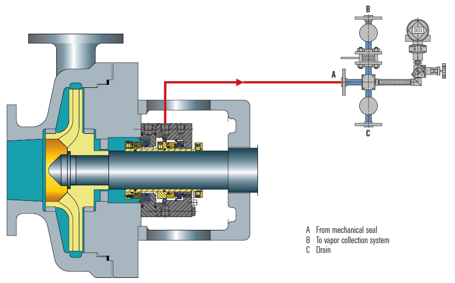
Seal faces can be designed to maintain a gas film between them rather than a fluid film. These piping plans are intended to work with theses gas film (dry running) seals. Plan 72 and 74 bring the buffer or barrier gas into the seal; plans 75 and 76 are for the gas exiting the seal.
Secondary seal is ordinarily running with a gas film between the faces. When the primary seal fails, the pumped fluid will fill the space between the primary and backup seal. The backup seal is now working as a liquid seal rather than a gas seal and is designed to run for about 8 hours, allowing the operators time for an orderly pump shutdown.
Plan 72 buffer gas flow keeps the gas in the seal from becoming concentrated from nuisance leakage over time so that any leakage from the gas backup seal is mostly inert flush gas and not toxic pump vapors.


 8613371530291