
api 682 mechanical seal price

After nearly six years of intensive work, the American Petroleum Institute (API) 682 mechanical seal standard is soon to be adopted. Since its introduction in 1994, API 682 has become “the” standard that sets the global tone for the procurement and operation of seal and supply systems for centrifugal pumps in the oil and gas sector as well as in the petrochemical industry. API 682 is a “living” standard that directly incorporates diverse practical experience in its regular updates.
Founded in 1919 and located in Washington, D.C., the API includes close to 500 companies from the oil and gas sector and the petrochemical industry. Since 1924, it has focused on technical standards. To this day, API has adopted roughly 500 standards that address diverse processes and components in detail—which ultimately ensure a maximum of operating and process reliability. API standards, which are clearly defined and in part attached to approval tests, do not take effect only in the U.S. In many cases, they have developed into worldwide industrial standards. API is often considered a synonym for safety and reliability.
Individual standards—including API 682 regulations for mechanical seals and seal supply systems—have become so popular that they have even been referenced in outside industry applications. The authors of the new edition point out that this was never the intention and clarify the actual purpose of the API 682 standards. The standards are for seal systems in pumps—not in agitators or compressors—and for oil and gas and petro chemistry—not for water supply or the food sector.
Initial information about mechanical seals was originally provided in the API 610 pump standard. During the 1990s, API 682 developed into a separate, more comprehensive standard for mechanical seals and supply systems. The API 682 standard is continually maintained and updated by end users and manufacturers. Another quality of API 682 is that it does not typically permit only a single technical solution. In addition to proven and tested standard solutions (defaults), the regulations also deliberately list alternatives (options) and even allow customized solutions (engineered solutions). This diversity is demonstrated more clearly in this edition than in previous ones.
The composition of the 25-member task force is representative of the practical way in which API approaches the topic of seals. Since 2006, the task force has been updating the 3rd Edition of API 682 that took effect in 2004 and is still valid. In addition to leading seal system manufacturers, the American-European expert panel—which intentionally counted on non-API member collaboration—also included renowned planning companies and representatives from some of the largest mineral oil groups, who are users of seal solutions.
While the currently valid API 682 edition included approximately 200 pages, the 4th Edition is 260 pages. The revised edition is organized into a body of text with 11 chapters and detailed annexes with a significantly expanded scope. For example, Annex I provides detailed information on more than 20 pages for API-conform seal qualification tests.
Default seals and options must be tested using five different media and clearly defined operating conditions representative of typical API applications. Together with the described seal designs, this yields a high number of possible test variations. In the process, the expended time per test and seal type can take up to 200 hours. The result for typical industry seal designs is documented in a test certificate and a detailed report. Customer-specific qualification tests can be agreed upon for engineered seals.
Essentially, checked and tested product safety is the core of the standard. The objective of API 682 is continuous operation of at least three years (25,000 operating hours subject to the legally stipulated emission values, or for maximum “screening value” of 1,000 parts per million by volume, EPA Method 21), increased operational reliability and simplified maintenance. The standards defined by API apply exclusively to cartridge systems with a shaft diameter of 20 to 110 millimeters and a defined range of operating conditions.
The 4th Edition also includes the revised product coding system (Annex D). The proven classification parameters “Category,” “Arrangement” and “Type” will be continued. They are listed first in the revised code and provide information about the setup and field of use of the respective API seal. The seal arrangement includes:Arrangement 1—single seals are differentiated
Details regarding the supply system—specified as “Plan”—are in the old and new code. The addition of precise information regarding material selection and shaft diameter is new. This gives more meaning to the code and guarantees a clear specification of the mechanical seal and its operation—from selection to documentation. Industry experts agreed that the expanded coding system will prove itself in practice and endure permanently.
The selection process of an API seal system is complicated. Several flow charts and tables on more than 10 pages are dedicated to this topic in the new edition. To provide more precision in the technical selection process when determining the arrangement, an alternative selection tool (Annex A.4) has been included in the 4th Edition for the first time. This method is based on the established “Risk & Hazard Code” and has been tested in practice.
The starting point is the pumped medium. Its real hazard potential is accurately recorded and described by the “Hazard & Risk Code” in the “Material Safety Data Sheets.” Decisions can be made quickly and securely, for example, about whether a single seal (Arrangement 1) will suffice, or if a double seal with barrier pressure system is required.
The experience-based, “lived” standard of the API 682 edition is demonstrated by the two silicon carbide (SiC) variants, reaction-bonded silicon carbide and self-sintered silicon carbide, which are treated equally as default materials for sliding surfaces in chemical (Category 1) as well as in refinery/oil and gas applications (Category 2 or 3). Until now, sintered SiC was set for chemical applications because of its superior chemical stability, whereas the reaction-bonded variant established itself in the refinery sector. This restrictive allocation was canceled because of practical application examples (best practices) that were brought to the attention of the task force, which called for a course correction.
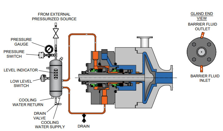
Plan 53 with a pressurized barrier fluid belongs to the more complicated supply systems. In detail, three types are possible:Plan 53A is the solution with the constructively least amount of effort. The pressure on the barrier medium is generated directly via gas pressurization—normally with nitrogen—in the tank. However, the application has limits, since higher barrier pressures could cause a dissolution of the nitrogen in the barrier medium. The consequence would be the risk of inadequate lubrication in the sealing gap of the mechanical seal. That is why Plans 53B and 53C are used for higher barrier pressure.
A new prescribed refilling interval of at least 28 days has also been included in the 4th Edition of API 682. The fluid reservoir must be large enough to supply the seal with barrier fluid for this entire period—without refilling. To obtain the most compact reservoirs, the seal manufacturers are required to find optimized system solutions with minimal leakage values for the barrier medium.
The transition to transmitters as default is illustrative: the API specifications primarily concern operating and process reliability and only then consider economic viability. This universal application is also verified by the decision of the task force to permit only seamless pipes in the future for “Piping” for the supply systems. The use of welded pipes, which would be less expensive, was considered unacceptable.
The task force also addressed the topic of heat resistance of the instrumentation used in supply systems pragmatically. In the past, frequent debates occurred regarding whether supply systems for high-temperature applications—for example, a 400 C approved pump—have to be equipped with special instrumentation for high temperatures. Now the temperature specification for the instrumentation has been limited to 100 C. If instruments with higher temperature limits are required in the future, the customer has to inform the seal vendor accordingly.
The essential improvements, in addition to the technical supplements and updates, are the clear structures of the latest API regulation. The body of the text was tightened and structured appropriately, whereas technical details and background information were placed in the annexes. Some of the wording in individual chapters was revised to improve understanding.
The improved user friendliness is shown in Annex E, which addresses structured communication and data exchange between suppliers and customers. Descriptions that previously encompassed many pages in API 682 are now bundled into two compact checklists in the 4th Edition. The first list systematically describes what must be considered for inquiries and quotations. It specifies the data that needs to be provided and the additional information and documents with which it must be combined. For example, seal systems that deviate from standardized API solutions must be shown separately. Annex E is completed by a second checklist that shows in which order the documentation is necessary.
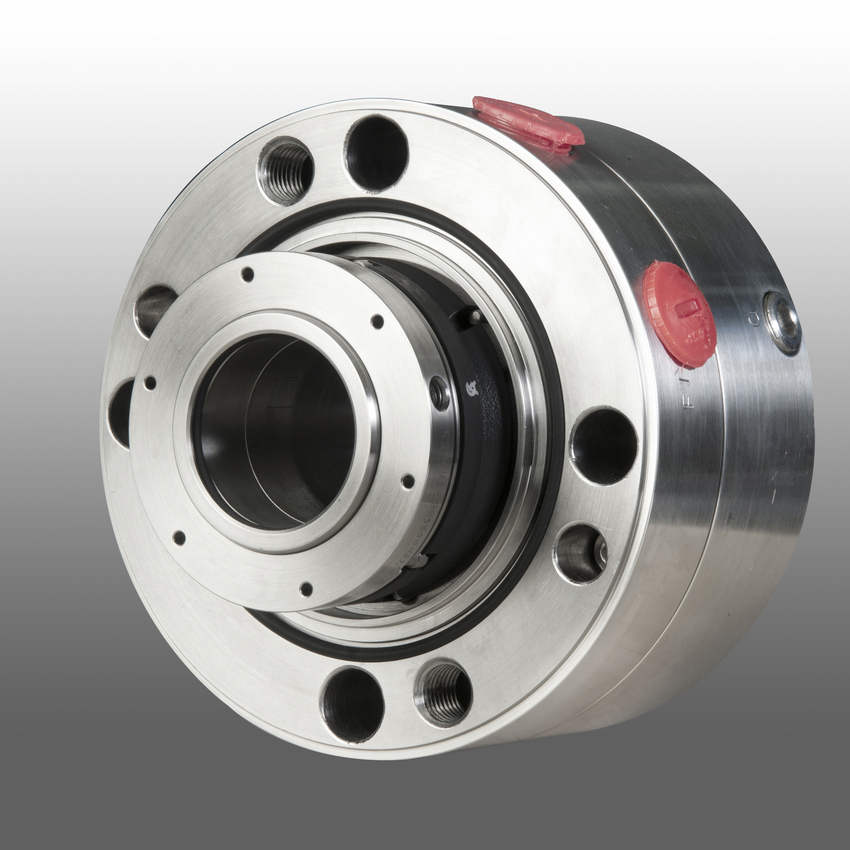
Apart from the numerous technical updates and improved user friendliness, one detail is visually the most striking innovation of this edition: all mechanical seals are equipped with red plugs in the supply connections of the seal gland upon delivery. Until the unit is installed, these plastic closures prevent the ingress of dirt in the seal. During operation, the connections are either assigned to pipelines, or the plastic plugs are replaced with enclosed metal plugs. An additional benefit is that the 4th Edition API seals are quickly identified by the red plugs. Editor’s Note: This article was previously published in Upstream Pumping Solutions, July/August 2013.
After more than five years of planning, the American Petroleum Institute (API) is preparing to release the 4th edition of API Standard 682 (ISO 21049:2011). The API 682 standard, which dates back to 1994 and is formally known as Shaft Sealing Systems for Centrifugal and Rotary Pumps, offers specifications and best practices for mechanical seals and systems to pump end users.
The standard’s latest edition began to take shape in 2006, when API formed a 4th edition task force to respond to end users’ questions and comments about previous editions. The task force soon realized that major changes, including reorganization and editing, would be necessary. While addressing every aspect of the resulting 4th edition (which is more than 250 pages long) would be impossible, this article summarizes the standard’s main points.
Those who use API 682 should understand the standard’s scope and remember that the standard does not include specifications for equipment outside that scope, such as engineered seals or mixers. Another important but often misunderstood point is that API 682’s figures are illustrative and not normative in their entirety.
For example, one of API 682’s figures shows a fixed throttle bushing combined with a rotating Type A seal, but seal manufacturers do not always have to combine these two components. The standard provides normative details in clauses and tables to help purchasers distinguish between requirements and suggestions.
The 4th edition continues to divide seals into three categories, three types and three arrangements. For all practical purposes, seal manufacturers can combine a seal’s component parts into nearly any orientation or configuration. Each orientation and configuration has advantages and disadvantages with respect to certain applications, performance and system disturbances.
Before the 4th edition, API 682 did not specify a minimum clearance between the inside diameter of a stationary seal part and the outside diameter of a rotating seal part. The 4th edition specifies this minimum clearance—typically the clearance between the sleeve and the mating ring. The specified clearances are representative of standard clearances that end users have used for decades. End users should not consider seal components to be “shaft catchers” to restrict shaft movement. The minimum clearance specified in API 682 also applies only to equipment within the standard’s scope. Equipment outside that scope, such as non-cartridge seals, older pumps, non-API 610 pumps and certain severe services, might benefit from larger clearances.
The new standard also updates the default bushings for the gland plate for the three seal categories. Fixed throttle bushings are now the default for Category 1 only, while floating bushings are the default for Categories 2 and 3.
While the 4th edition features the recommended seal selection procedure from the standard’s first three editions, it adds an alternative selection method in Annex A. Proposed by task force member Michael Goodrich, this alternative method recommends using material data sheet information to select a sealing arrangement.
Plans 66A and 66B are new to the standard, although end users have used them previously in pipeline applications. These plans detect and restrict excessive leakage rates in case of an Arrangement 1 seal failure.
The 4th edition has revised the data sheets in Annex C extensively to make them the same for all seal categories. Only two data sheets are included in the 4th edition—one in metric units and one in U.S. customary units. The new edition also folds Annex J into Annex E.
Previous editions of API 682 required metal plugs and anaerobic sealants when shipping new or repaired cartridges. After much debate, the task force decided that threaded connection points should be protected with plastic plugs for shipment. These plastic plugs should be red and have center tabs that operators can pull easily to distinguish the plugs from metal plugs. Shippers should also attach yellow warning tags to the plugs to indicate that end users need to remove the plugs before operation.
Although tutorial notes are scattered throughout API 682, this edition expands the tutorial section, Annex F, from seven pages to 42 pages. The expanded annex includes illustrative calculations. In particular, users interested in systems such as Plan 53B will find Annex F to be useful.
The 4th edition of API 682 is the product of more than 20 years of discussion, debate, usage and peer review. It includes a strong set of defaults and is by far the best and most logical starting point for mechanical seal and systems use. Equipment operators should take the time to familiarize themselves with API 682 to get the most out of this comprehensive standard.
Mechanical seals became the dominant sealing technology in refineries and chemical plants in the 1980s, causing the American Petroleum Institute (API) to establish a committee whose sole focus was to write standards for these components. The first edition, API 682 Shaft Sealing Systems for Centrifugal and Rotary Pumps was published in 1994 with this mission statement, “This standard is designed to default to the equipment types most commonly supplied that have a high probability of meeting the objective of at least three years of uninterrupted service while complying with emissions regulations."Currently in its fourth edition, API 682 continues to offer guidance based on process service for both mechanical seals and their support systems.
While much of the standard is focused on mechanical seals, a significant portion is devoted to seal support systems, as they are a critical component to the proper functioning of the seal and pump system. As a manufacturer of seal support systems, Swagelok Company and our sales and service centers have implemented the best practices of API 682 4th Edition. In this blog post, we will explain what some of those best practices are, and how implementing recommendations from the standard in the construction and design of your seal support systems can help you meet your goals of increasing reliability and safety while reducing costs.
Before we discuss best practices, let’s look at the functions of seal support systems. These systems are designed for a specific mechanical seal and set of process conditions. Typically, they supply either a gas or a liquid to the mechanical seal to regulate the environment in which the seal operates, protecting rotating equipment from damage.
Throughout API 682 4th Edition, there are references to reducing the number of connections in seal support systems. Whether welded pipe or tubing is selected for the system, threaded systems are discouraged. Every connection can be viewed as a potential leak point and possible reliability risk in hydrocarbon pumping applications. Leaks on seal support systems near pumps can cause asset damage, increased downtime, environmental issues, and safety risks.
In the past, many seal support systems were constructed out of pipe due to piping being historically preferred. More recently, seal manufacturers, end users, and pump OEMS have implemented tubing as a connection solution in seal support systems due to its long history of successful use in critical applications throughout the industrial world. As rotating equipment expert Heinz Bloch noted in a recent Hydrocarbon Processing article, “[the] American Petroleum Institute Standard 682 (API 682) began to endorse the use of tubing for some seal piping plans. Regrettably, tradition-bound purchasers still opt for hard pipe; we are asking them to reconsider. API 682 (4th Edition) now specifies seal support system connections almost interchangeably.”
Tubing can be utilized to reduce the number of connections by bending lines and appropriately using adapter fittings. Often, the only needed connections are those at the seal and the sealing system. Since tubing is annealed, bending the tubing work hardens the metal, increasing the strength of the tube at the bend. Innovative connection technologies such as flange adapters and extended male connectors further reduce the number of connections from threaded ports on the seal and seal pots by eliminating the need for multiple fittings. The use of tubing provides further financial benefit when we examine the MRO costs of the pump, seal, and support system. During maintenance operations where “piping” around pumps is reworked, the use of tubing eliminates the need for costly on-site welding and can be installed quickly to reduce downtime.
Seal support systems are critical to the proper operation of the seal and pump, and as such, require regular visual inspection. Making the job of visual inspection simple promotes system reliability and safety. When designing seal support systems, there are several best practice design principles to consider once the piping plan and general arrangement have been selected.
Mechanical seals are often damaged when pumps are started and stopped, sometimes as the result of improper seal support system operation. If the design of the seal support system facilitates proper operation, common mistakes when commissioning pumps can be avoided.
Additionally, API 682 supports these design considerations. It states: “All controls and instruments shall be located and arranged to permit easy visibility by the operators, as well as accessibility for tests, adjustments, and maintenance” (9.1.5)
Lastly, panels can include part numbering information, flow path indication, and operator instructions. These improvements help ensure safe and reliable startup and shutdown of pumps and seal support systems.
API 682 4th Edition also recommends block-bleed configurations for all gauges. If systems are not designed with this feature, it is likely that as gauges fail, operators will be left without critical information until the next turnaround or project when the pump and support system can be decommissioned and the gauge replaced.
Lastly, there are a wide variety of tubing connections and design options that allow for every serviceable component on a seal support system to be easily removed and replaced while continuing to operate the system. For seal pots, the 4thEdition stipulates “Local operation, venting, filling, and draining shall be accomplished from grade. Unless otherwise specified, systems that require the use of a ladder or step or that require climbing on the baseplate or piping are not acceptable” (8.1.8) .
Implementing these basic best practice design principles for mechanical seal support system increases reliability and reduces costs. To recap how you can realize better results with your systems:
Bringing pumps offline to fix minor instrumentation issues or fill seal pots should not be acceptable. Locating these systems on panels, with proper labeling and designing for easy maintenance reduces the chance for operator error which can damage seals.
Seal failures and the associated costs of seal replacement should be of great concern to rotating equipment groups at all plants. Ensuring that the best practices and design principals of API 682 4th Edition are followed helps prevent these costs and creates a safer and more reliable operation.
Swagelok provides design and assembly of seal support systems through our network of more than 200 authorized sales and service centers. We offer configurable, local, and reliable systems that are better by design to help you reduce costs, save time, and improve safety of your rotating equipment.
For additional advice on designing and installing your mechanical seal support systems, or to find the right API seal plan kits or assemblies for your applications, reach out to your local Swagelok team.
Several operational variables must be considered when choosing an API 682 piping plan for dual pressurized seals. These variables include flow rate, heat load, normal operating pressure, the number of mechanical seals to be serviced, and available utility requirements. Each seal support system will have advantages and disadvantages in relation to the variable operating conditions of API 682 Plan 53B and Plan 54 piping plans. Each application should be evaluated on a case-by-case basis for mechanical seal longevity and reliability.
A Plan 53B system utilizes a bladder accumulator to provide a typical operating pressure of 30- 50 psi above maximum seal chamber pressure when servicing one mechanical seal per system. The bladder accumulator prevents gas entrainment for operating pressures above 200 psi. The bladder is pre-charged with nitrogen using a charging kit and Schrader valve (like a car tire) and creates a separation between the nitrogen source and seal support barrier fluid. As a mechanical seal leaks barrier fluid into the process fluid, the operating pressure will drop until an alarm signals personnel to refill the unit until normal operating barrier pressure is returned. A refill period of 20 – 30 days is targeted and is based on bladder accumulator size (5, 10, or 15 gallons), seal leakage, and normal operating pressure.
Higher barrier pressure differential operating pressures above maximum seal chamber pressure will increase available usable fluid. Specifications requiring an increase from 50 to 100 psi above maximum seal chamber pressure will result in an increased time period before re-filling, assuming the usable fluid increase is not exceeded by an increase in seal leakage. However, the higher seal face leakage and increased heat generation which may occur at a higher barrier pressure differential must be accounted for in the mechanical seal / seal support design. Barrier differential pressures above 100 psi over maximum seal chamber pressure are not recommended due to diminishing returns between heat generation and increased leakage rates.
Plan 53B systems have an estimated maximum heat removal rate of 8,000 – 12,000 BTU/HR for target barrier fluid supply temperatures of 120°F. As heat removal rates exceed 12,000 BTU/HR, target temperatures and other seal support piping plans can be evaluated on a case-by-case basis.
Other factors to consider are flow rate and fluid circulation: either can be achieved by utilizing a pumping ring or an external gear pump. Pumping designs without pumping rings will require an external mag-driven positive displacement gear pump with typical flow rates of 1 to 3 GPM and can be less cost effective when compared to a Plan 54. A Plan 53B with an external gear pump is a closed loop system requiring the external pump to have the same pressure on suction as discharge. Appropriately-sized entry glands to and from the seal as well as the limited use of elbows should be utilized to prevent a differential pressure of 75 psi maximum between the lubricator pump suction and discharge, otherwise the lubricator pump can decouple. A Plan 54 is an open loop system with an atmospheric tank and filler/breather. Depending on the main pumping process, a Plan 53B closed loop system may be optimal for containment purposes with respect to environmental health and safety concerns in the event of a system upset.
An API 682 Plan 54 is available for those applications where operating capabilities such as flow rates, heat load requirements, normal operating pressures, and seal-per-system limitations exceed acceptable Plan 53B guidelines. The Plan 54’s normal operating pressure remains constant in relation to seal leakage unlike a Plan 53B where normal operating pressure decreases with leakage.
One Plan 54 can service one or multiple mechanical seals. When multiple systems are serviced by one Plan 54, all these systems must be evaluated for critical operation in the event of system failure. If deemed necessary, a redundancy plan to prevent system failure can be included in the design. Redundancy equipment can include primary and back up lubricator pumps, duplex filter assemblies, and dual heat exchangers. Multiple mechanical seals can be isolated and serviced without shut down, allowing other equipment to remain online and operational. A secondary power supply – when available – is recommended for a backup pump motor in event of main power disruption.
The Plan 54 holds a specific advantage over Plans 53 A/B/C because location proximity to the main pump is not required. In addition, Plan 54 selection is driven by shaft speed, circulation device limitations, and heat load. These specifications differ from the Plan 53 series’ required circulation rate which relies on size, circulation device, and piping to cool and lubricate mechanical seals.
A Plan 54 operates 30 – 50 psi above maximum seal chamber pressure and remains constant. For seal chamber pressure fluctuations, plan equipment can include digital pressure tracking control to maintain a 30 – 50 psi bias versus using constant pressure regulators. A pressure transmitter on the seal chamber references a pressure transmitter on the Plan 54 system to maintain a bias through DCS. Alternatively, using a pressure tracking mechanical valve with a reference line to seal chamber can maintain bias through mechanical means.
Simplex or duplex filter assembly options are included. Duplex filter assemblies allow elements to be changed while unit is running and operational. Differential pressure instrumentation is included for monitoring element condition and signaling when the element should be replaced. Filter assemblies can be upstream or downstream of the mechanical seal. Typical arrangement downstream is under atmospheric conditions. Placement on supply is required to meet the pump protection valve setting.
Transmitters or mechanical switch instrumentation is offered for equipment monitoring. Alarm logic for level, pressure, flow, and temperature is typical. Considerations for alarm logic is based on system complexity or the number of seals on the system.
Lastly, a Plan 54 can be equipped with a bladder accumulator safety package. Located upstream, the package includes a bladder accumulator and check valve on supply. The downstream package includes a normally closed solenoid or actuating ball valve on return. The solenoid can receive a signal to fail closed, maintaining a positive pressure for short periods of time which may be hours or days depending on seal leakage rate. This prevents reverse pressurization during upset and allows time for trouble shooting.

A brand new mechanical seal provides a specific level of protection against pump leakage, but by itself, it can’t necessarily ensure the level of leak protection you need in your Northern California refinery. Here’s why: The API 682 Integrity Test is designed to identify mechanical seal manufacturing defects and assembly errors. This mechanical seal leak test procedure isn’t designed to simulate the seal’s actual performance under operating conditions, and the test certainly has its limitations.
One test is used regardless of seal design. It doesn’t differ according to seal arrangement, materials, face technology, size, or mating ring proportions. These and several other factors affect seal performance. Even though most mechanical seals effectively seal both air and liquids at low pressure, not all do. For example, high-pressure seals with low balance ratios satisfactorily seal liquids but leak air. Mechanical seals with polished faces have less air leakage in comparison to special (matte) face finishes. Contacting seals have less leakage than non-contacting seals. So one test doesn’t cover all bases.
The API 682 Integrity Test permits a maximum pressure drop of 0.14 bar (2 psig) over a five minute period from a maximum 28 liter (1cu ft) reservoir pressurized to 1.7 barg (25 psig). This represents a leakage rate of 56.9 g/hr of air, based on the ideal gas laws.
For a Bay Area refinery concerned with fugitive emissions and possible sanctions from Cal/OSHA or BAAQMD, that leakage rate is unacceptable. So, even though the API 682 Integrity Test can catch manufacturing defects, you’re not guaranteed leak-free performance. That’s where mechanical seal support systems bridge the gap between the mechanical seal leak test procedure limitations and a refinery’s stringent requirements.
A seal support system properly configured for your mechanical seal and pumping process helps minimize the chance of pump leakage. There are near-infinite combinations of pumping conditions, mechanical seals, and seal support systems. To help navigate this complexity of options, I recommend seeking the guidance of an experienced seal support system supplier. They’ll work with you to assess the specific requirements of each pump, mechanical seal, and process conditions. Based on the assessment, they’ll recommend the mechanical seal support system plan and configuration to help ensure you comply with Cal/OSHA and BAAQMD regulations and extend the mechanical seal’s life.
Proper configuration tailors the seal support system to the specific temperature, pressure, and process fluid conditions of the pumping process. Components are selected to help ensure the optimum operating environment for each mechanical seal.
Coolers or heat exchangers rated to maintain process or flush fluid at a temperature to sufficiently remove heat from seal faces and prevent thermal distortion of seal faces that inevitably result in leakage
Barrier fluids pressurize by nitrogen, bladder accumulator, piston accumulator, or an external pump to maintain the correct between-seal pressure for dual/tandem seal arrangement
Valves, pressure gauges, and pressure transmitters to monitor pressure and alert to variations that could lead to unacceptable leakage across inboard and outboard seal faces
A well-configured echanical seal support system begins with matching the proper seal support plan to the mechanical seal type and then refines the plan with components tailored to the specific pumping conditions.
A properly configured mechanical seal support system will incorporate the components and function to maximize pump reliability. That configuration should also provide easy accessibility by operations and maintenance personnel.
For more than 50 years Swagelok has been working with refineries in Northern California. Our expert Field Engineers are available to consult on-site to assess your requirements and recommend solutions tailored to your specific pumping needs. Swagelok’s petroleum industry experience, highest-quality components, and assembly services enable us to design, fabricate, and test (following ISO 9001 quality standards) mechanical seal support systems to help minimize mechanical seal leaks and meet stringent California environmental standards.
To find out more about how Swagelok Northern California can help you select the right API plan for dry gas seals for your specific process needs, contact our team today by calling
Paul holds a B.S. in Mechanical Engineering from North Dakota State University. Before joining Swagelok Northern California, he was the West Coast Regional Sales Manager for an organization focused within the pneumatic and hydraulic industry where he supervised product distribution throughout the western United States, Canada, and Mexico. While in this role, he was able to help provide technical and application-specific expertise to customers and distribution to drive specifications.


 8613371530291