
api 682 mechanical seal pricelist
The MTM250 series of cartridge mechanical seals has been specially designed to be installed on rotary machines as fast as compressors and turbines. It can be realized in different materials, both for the sliding faces and structural materials and it is able to withstand speeds up to 32 m / s. It is available from diameter 40 up to 200mm and it is today mainly used on screw compressors in presence of lubrication. Its design has been optimized thanks to the testing done directly on the field with one of the major manufacturers in the industry, following out the API 619 norm. Today it is used for pumping gas, such as propane, methane, butane and major hydrocarbons. The structure of the MTM250 cartridge mechanical seal is a double type structure with an external safety sealing, SafetyMTM, which becomes the third seal in case of failure of the two main seals.

The Stein Seal® Company has developed API1 STANDARD 682 seals for the oil and gas industry. Stein Seal® has designed, manufactured and tested the seals according to the rigorous API Standard 682 test protocols. In general, these are balanced seals with cartridge construction. These seals are classified in to Types, Category, Arrangements and Configurations. The seals are designed and tested to operate continuously for 25,000 hours without need for replacements.
Type A seal is a balanced, internally-mounted, cartridge design, pusher seal with multiple springs. Secondary sealing elements are elastomeric O-rings.
Category 1 are intended for use in non API 610 pump seal chambers, meeting the dimensional requirements of ASME B 73.1 and ASME B73.2 seal chamber dimensions and their application is limited to seal chamber temperatures from -40°F to 500°F (-40°C ~ 260°C) and gauge pressures up to 300 psi (2 MPa / 20 bar).
Category 2 are intended for use in API 610 pump seal chambers dimensional requirements. Their application is limited to seal chamber temperatures from -40°F to 750°F (-40°C ~ 400°C) and gauge pressures up to 600 psi (4 MPa / 40 bar).
Category 3 provides the most rigorously tested and documented seal design. They meet the seal chamber envelope requirements of API 610 (or equal). Their application is limited to seal chamber temperatures from -40°F to 750°F (-40°C ~ 400°C) and gauge pressures up to 600 psi (4 MPa / 40 bar).
Arrangement 2 seals having two seals per cartridge assembly, utilizing the externally supplied buffer fluid at a pressure less than the seal chamber pressure.
Arrangement 3 seals having two seals per cartridge assembly, utilizing the externally supplied barrier fluid at a pressure higher than the seal chamber pressure.
Face-to-back configuration – These seal are Arrangement 2 or 3 seals. In which one stationary face is mounted between two flexible rotary unit or one flexible rotary unit between two stationary face. The inner seal is OD pressurized by process fluid and barrier or buffer fluid is on the ID of the inner seal. The outer seal OD pressurized by barrier or buffer fluid.
Back-to-back configuration – These seal are Arrangement 2 or 3 seals. In which both the rotary faces are mounted between two stationary flexible units. The pumping fluid is on the ID of the inner seal, and the barrier (pressurized) or buffer (un pressurized) fluid is on the OD of the inner and outer seal.
Face-to-face configuration – These seal are Arrangement 2 or 3 seals. In which both the rotary faces are mounted between two flexible stationary units. The pumping fluid is on the ID of the inner seal, and the barrier (pressurized) or buffer (un pressurized) fluid is on the OD of the inner and outer seal.
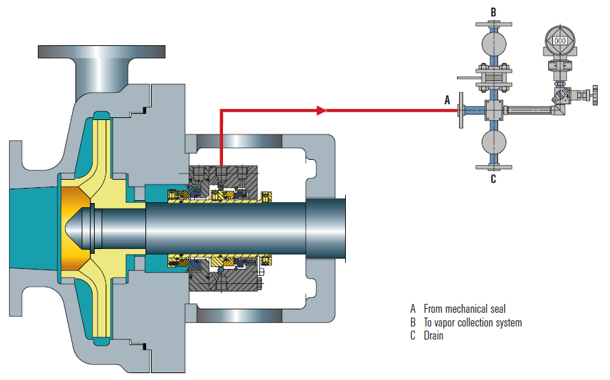
A seal piping plan is designed, manufactured and supplied to improve the environment around the mechanical seal and therefore increase the performance and reliability of the seal. Piping plans range from very simple systems such as fluid recirculation into the seal chamber to complex systems which provide pressurization, cooling and circulation for support fluids and gases. The basic operation of the piping plan and also the requirements for instrumentation are followed as per API Standard 682 guidelines. Major piping plans supplied by Stein Seal® are Plan-21, Plan-23, Plan-32, Plan-52, Plan-53A, Plan-53B & Plan-53C.
Our API 682 seal design features, manufacturing capabilities and test facilities are witnessed and certified by a third party international certification organization. API 682 product offerings and capabilities can be found on our website www.steinseal.in
The APILITE (R) mechanical seal is a new addition to the API 682 RDT cartridge seal family. It is designed for sealing heavy and light hydrocarbons, including VOCs, and other hazardous fluids at oil refineries and petrochemical plants, gas plants, and chemical plants. APILITE RDT seal is an o-ring dual seal to be used with API Plan 52, 53, or 54.
Minimized bending of seal rings allows for stable operation under higher pressures and for longer MTBR (mean time between repair) because of less wear;
Interchangeability of many parts and design solutions with the SD APITERM seal reduces inventory of spare parts, lets the seal survive under pump dry-running, and decreases prices by encreasing parts production volume;

Not only do we handle all styles of seals and environmental controls, we can also repair, modify and even build what you need when standard products don’t do the job. We repair all brands in-house.
We just don"t know of another company that can do so much for you in the murky world of mechanical seals. With our training programs, we can even make the murkiness go away.
The family of shaft seals known as mechanical seals is the most advanced type of seal used in the mixing industry. They can handle the highest pressures, maintain nearly leak-free operation, and require minimum maintenance if installed and operated properly. The downside is the higher initial cost (both for the seal and for the more complicated equipment required surrounding the seal) and the expertise needed to service the seals. Mechanical seals are increasing in popularity due to the growing environmental restrictions regarding any leakage from process tanks.
There are hundreds of mechanical seal designs, but they all are variations of a basic layout consisting of a collar mounted on the shaft which uses springs to push a ring (which also rotates with the shaft) against another ring that is held stationary. The rings rotate against each other riding on a thin layer of lubricant, and the springs hold them so tightly together that leakage through the seal is reduced to an immeasurable amount. The mating surfaces of the rings must be perfectly flat to seal properly, and are manufactured to tolerance measured “light- bands." The rings must also be extremely hard to endure the pressure and wear, so they are usually made up of ceramic, carbon, silicon carbide, tungsten carbide or similar materials. The stationary “seat” is held in place and maintains a static seal with the mounting housing using gaskets or o-rings. The rotating elements of the seal must attain a static seal with the shaft using o-rings, wedges or packing.

The Flexaseal Style 59A is designed specifically to conform to API 682 Category 2 Applications for Midstream and Downstream Oil and Gas Applications. Standard design features include:
The 59A is also available with contacting and noncontacting secondary sealing. The Flexaseal FC seal (Available as 59A/FC) provides decades of proven operational reliability as a contacting secondary seal. The Flexaseal FGSA (Available as 59A/FGSA) is our newest lift-off design for API applications that require a noncontacting secondary seal.
After nearly six years of intensive work, the American Petroleum Institute (API) 682 mechanical seal standard is soon to be adopted. Since its introduction in 1994, API 682 has become “the” standard that sets the global tone for the procurement and operation of seal and supply systems for centrifugal pumps in the oil and gas sector as well as in the petrochemical industry. API 682 is a “living” standard that directly incorporates diverse practical experience in its regular updates.
Founded in 1919 and located in Washington, D.C., the API includes close to 500 companies from the oil and gas sector and the petrochemical industry. Since 1924, it has focused on technical standards. To this day, API has adopted roughly 500 standards that address diverse processes and components in detail—which ultimately ensure a maximum of operating and process reliability. API standards, which are clearly defined and in part attached to approval tests, do not take effect only in the U.S. In many cases, they have developed into worldwide industrial standards. API is often considered a synonym for safety and reliability.
Individual standards—including API 682 regulations for mechanical seals and seal supply systems—have become so popular that they have even been referenced in outside industry applications. The authors of the new edition point out that this was never the intention and clarify the actual purpose of the API 682 standards. The standards are for seal systems in pumps—not in agitators or compressors—and for oil and gas and petro chemistry—not for water supply or the food sector.
Initial information about mechanical seals was originally provided in the API 610 pump standard. During the 1990s, API 682 developed into a separate, more comprehensive standard for mechanical seals and supply systems. The API 682 standard is continually maintained and updated by end users and manufacturers. Another quality of API 682 is that it does not typically permit only a single technical solution. In addition to proven and tested standard solutions (defaults), the regulations also deliberately list alternatives (options) and even allow customized solutions (engineered solutions). This diversity is demonstrated more clearly in this edition than in previous ones.
The composition of the 25-member task force is representative of the practical way in which API approaches the topic of seals. Since 2006, the task force has been updating the 3rd Edition of API 682 that took effect in 2004 and is still valid. In addition to leading seal system manufacturers, the American-European expert panel—which intentionally counted on non-API member collaboration—also included renowned planning companies and representatives from some of the largest mineral oil groups, who are users of seal solutions.
While the currently valid API 682 edition included approximately 200 pages, the 4th Edition is 260 pages. The revised edition is organized into a body of text with 11 chapters and detailed annexes with a significantly expanded scope. For example, Annex I provides detailed information on more than 20 pages for API-conform seal qualification tests.
Default seals and options must be tested using five different media and clearly defined operating conditions representative of typical API applications. Together with the described seal designs, this yields a high number of possible test variations. In the process, the expended time per test and seal type can take up to 200 hours. The result for typical industry seal designs is documented in a test certificate and a detailed report. Customer-specific qualification tests can be agreed upon for engineered seals.
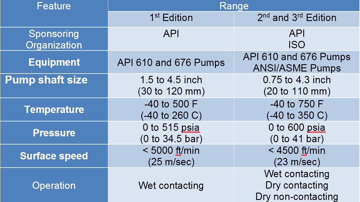
Essentially, checked and tested product safety is the core of the standard. The objective of API 682 is continuous operation of at least three years (25,000 operating hours subject to the legally stipulated emission values, or for maximum “screening value” of 1,000 parts per million by volume, EPA Method 21), increased operational reliability and simplified maintenance. The standards defined by API apply exclusively to cartridge systems with a shaft diameter of 20 to 110 millimeters and a defined range of operating conditions.
The 4th Edition also includes the revised product coding system (Annex D). The proven classification parameters “Category,” “Arrangement” and “Type” will be continued. They are listed first in the revised code and provide information about the setup and field of use of the respective API seal. The seal arrangement includes:Arrangement 1—single seals are differentiated
Details regarding the supply system—specified as “Plan”—are in the old and new code. The addition of precise information regarding material selection and shaft diameter is new. This gives more meaning to the code and guarantees a clear specification of the mechanical seal and its operation—from selection to documentation. Industry experts agreed that the expanded coding system will prove itself in practice and endure permanently.
The selection process of an API seal system is complicated. Several flow charts and tables on more than 10 pages are dedicated to this topic in the new edition. To provide more precision in the technical selection process when determining the arrangement, an alternative selection tool (Annex A.4) has been included in the 4th Edition for the first time. This method is based on the established “Risk & Hazard Code” and has been tested in practice.
The starting point is the pumped medium. Its real hazard potential is accurately recorded and described by the “Hazard & Risk Code” in the “Material Safety Data Sheets.” Decisions can be made quickly and securely, for example, about whether a single seal (Arrangement 1) will suffice, or if a double seal with barrier pressure system is required.
The experience-based, “lived” standard of the API 682 edition is demonstrated by the two silicon carbide (SiC) variants, reaction-bonded silicon carbide and self-sintered silicon carbide, which are treated equally as default materials for sliding surfaces in chemical (Category 1) as well as in refinery/oil and gas applications (Category 2 or 3). Until now, sintered SiC was set for chemical applications because of its superior chemical stability, whereas the reaction-bonded variant established itself in the refinery sector. This restrictive allocation was canceled because of practical application examples (best practices) that were brought to the attention of the task force, which called for a course correction.
Plan 53 with a pressurized barrier fluid belongs to the more complicated supply systems. In detail, three types are possible:Plan 53A is the solution with the constructively least amount of effort. The pressure on the barrier medium is generated directly via gas pressurization—normally with nitrogen—in the tank. However, the application has limits, since higher barrier pressures could cause a dissolution of the nitrogen in the barrier medium. The consequence would be the risk of inadequate lubrication in the sealing gap of the mechanical seal. That is why Plans 53B and 53C are used for higher barrier pressure.
A new prescribed refilling interval of at least 28 days has also been included in the 4th Edition of API 682. The fluid reservoir must be large enough to supply the seal with barrier fluid for this entire period—without refilling. To obtain the most compact reservoirs, the seal manufacturers are required to find optimized system solutions with minimal leakage values for the barrier medium.
The transition to transmitters as default is illustrative: the API specifications primarily concern operating and process reliability and only then consider economic viability. This universal application is also verified by the decision of the task force to permit only seamless pipes in the future for “Piping” for the supply systems. The use of welded pipes, which would be less expensive, was considered unacceptable.
The task force also addressed the topic of heat resistance of the instrumentation used in supply systems pragmatically. In the past, frequent debates occurred regarding whether supply systems for high-temperature applications—for example, a 400 C approved pump—have to be equipped with special instrumentation for high temperatures. Now the temperature specification for the instrumentation has been limited to 100 C. If instruments with higher temperature limits are required in the future, the customer has to inform the seal vendor accordingly.
The essential improvements, in addition to the technical supplements and updates, are the clear structures of the latest API regulation. The body of the text was tightened and structured appropriately, whereas technical details and background information were placed in the annexes. Some of the wording in individual chapters was revised to improve understanding.
The improved user friendliness is shown in Annex E, which addresses structured communication and data exchange between suppliers and customers. Descriptions that previously encompassed many pages in API 682 are now bundled into two compact checklists in the 4th Edition. The first list systematically describes what must be considered for inquiries and quotations. It specifies the data that needs to be provided and the additional information and documents with which it must be combined. For example, seal systems that deviate from standardized API solutions must be shown separately. Annex E is completed by a second checklist that shows in which order the documentation is necessary.
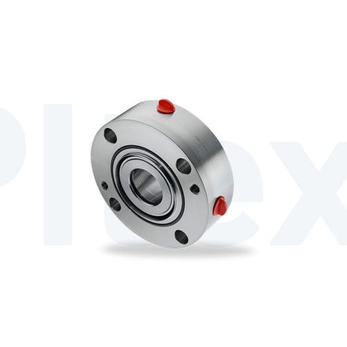
Apart from the numerous technical updates and improved user friendliness, one detail is visually the most striking innovation of this edition: all mechanical seals are equipped with red plugs in the supply connections of the seal gland upon delivery. Until the unit is installed, these plastic closures prevent the ingress of dirt in the seal. During operation, the connections are either assigned to pipelines, or the plastic plugs are replaced with enclosed metal plugs. An additional benefit is that the 4th Edition API seals are quickly identified by the red plugs. Editor’s Note: This article was previously published in Upstream Pumping Solutions, July/August 2013.


 8613371530291