
api 682 mechanical seal quotation
Mechanical seal failure due to unfavorable operating conditions is an issue in every industry. Double mechanical seals especially require proper sealing accessories to create suitable operating environments which are key to increasing MTBF. Reservoir systems are one of the most common and effective options to supply cooling fluid crucial to successful seal operation.
A double -or dual – cartridge seal is defined as an arrangement of two mechanical seals in a series. These seals may be configured in various orientations within the cartridge. The seals themselves are referred to as the “primary” (or inboard) seal and the “secondary” (or outboard) seal. A double seal arrangement is the superior option to a single cartridge when it is imperative the product being pumped does not leak into the atmosphere. The API (American Petroleum Institute) Standard 682 classifies dual seals into two configurations. These configurations also apply to ASME (American Society of Engineers) B73.1 and ASME B73.2 pump designs.
Arrangement 2 (Unpressurized) Designs: the buffer fluid is the operating environment for the secondary seal and forms a “buffer” between the process fluid and the atmosphere.
Arrangement 3 (Pressurized) Designs: the barrier fluid is the operating environment for both the inboard and outboard seal, preventing process leakage to the atmosphere.
Buffer and barrier fluids may be either liquid or gas. These fluids lubricate seal faces during operation as well as regulate operating temperatures by moving heat—both generated and absorbed—away from the faces.
Seal support systems are necessary for the smooth operation of a dual mechanical seal. Here are two of the most common piping plans for these systems.
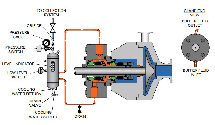
This is an unpressurized system consisting of a reservoir, supply and return lines, and an internal circulation device within the outer seal (commonly referred to as a pumping ring). The buffer fluid circulation rate is dependent on how this circulation device functions during seal operation.
Reservoirs may be fitted with a variety of measurement devices such as a liquid level indicator and pressure gauges as well as valves and switches to aid in various operation and maintenance functions. For instance, a typical support system configuration for natural gas liquids (NGL) would issue an alarm (visual, audible, or both) when the inner seal fails. In addition, the outer seal would take over the primary seal function until maintenance is performed.
This system forces gas from an external pressurized source into the reservoir to pressurize the barrier fluid. This means the reservoir pressure will be above seal chamber pressure; a guideline is a minimum of 20 to 25 psig (1.4 to 1.73 bar) above the maximum process pressure.
The Plan 53A is also used to maintain a specific operating temperature range to ensure optimum lubrication at the seal faces. The reservoir houses a cooling coil which actively cools the barrier fluid as necessary.
As with the Plan 52, a circulation device is used to move the barrier fluid. Replenishing a Plan 53A system with fresh barrier fluid can be as simple as a using a hand pump or a more complex arrangement which satisfies multiple seals.
Liquid-lubricated dual mechanical seals require an external source of clean, cool lubricating fluid. The following fluid reservoir systems create this enhanced sealing environment, enabling longer operational life for dual seals.
In the oil and gas industry, reliable seal operation is critical to running efficient, safe processes. In conjunction with API 682 Piping Plans 52 and 53A, seal support systems aid in smooth seal operation.
If you require an engineered seal support system or are interested in additional options to Flexaseal’s ANSI PLUS and ANSI LITE support systems, please contact our applications engineering team.

To keep mechanical seal systems functioning as long as possible, we recommend using standardized seal piping plans. Detailed API seal piping plans ensure minimal seal face wear by maintaining the optimal seal chamber environment.
Since they were first formulated, seal piping plans have been maintained and remodeled by the American Petroleum Institute (API). Current plans are based on API 682 and are sorted numerically. In some cases, designated letters are also used to differentiate between plans.

After more than five years of planning, the American Petroleum Institute (API) is preparing to release the 4th edition of API Standard 682 (ISO 21049:2011). The API 682 standard, which dates back to 1994 and is formally known as Shaft Sealing Systems for Centrifugal and Rotary Pumps, offers specifications and best practices for mechanical seals and systems to pump end users.
The standard’s latest edition began to take shape in 2006, when API formed a 4th edition task force to respond to end users’ questions and comments about previous editions. The task force soon realized that major changes, including reorganization and editing, would be necessary. While addressing every aspect of the resulting 4th edition (which is more than 250 pages long) would be impossible, this article summarizes the standard’s main points.
Those who use API 682 should understand the standard’s scope and remember that the standard does not include specifications for equipment outside that scope, such as engineered seals or mixers. Another important but often misunderstood point is that API 682’s figures are illustrative and not normative in their entirety.
For example, one of API 682’s figures shows a fixed throttle bushing combined with a rotating Type A seal, but seal manufacturers do not always have to combine these two components. The standard provides normative details in clauses and tables to help purchasers distinguish between requirements and suggestions.
The 4th edition continues to divide seals into three categories, three types and three arrangements. For all practical purposes, seal manufacturers can combine a seal’s component parts into nearly any orientation or configuration. Each orientation and configuration has advantages and disadvantages with respect to certain applications, performance and system disturbances.
Before the 4th edition, API 682 did not specify a minimum clearance between the inside diameter of a stationary seal part and the outside diameter of a rotating seal part. The 4th edition specifies this minimum clearance—typically the clearance between the sleeve and the mating ring. The specified clearances are representative of standard clearances that end users have used for decades. End users should not consider seal components to be “shaft catchers” to restrict shaft movement. The minimum clearance specified in API 682 also applies only to equipment within the standard’s scope. Equipment outside that scope, such as non-cartridge seals, older pumps, non-API 610 pumps and certain severe services, might benefit from larger clearances.
The new standard also updates the default bushings for the gland plate for the three seal categories. Fixed throttle bushings are now the default for Category 1 only, while floating bushings are the default for Categories 2 and 3.
While the 4th edition features the recommended seal selection procedure from the standard’s first three editions, it adds an alternative selection method in Annex A. Proposed by task force member Michael Goodrich, this alternative method recommends using material data sheet information to select a sealing arrangement.
Plans 66A and 66B are new to the standard, although end users have used them previously in pipeline applications. These plans detect and restrict excessive leakage rates in case of an Arrangement 1 seal failure.
The 4th edition has revised the data sheets in Annex C extensively to make them the same for all seal categories. Only two data sheets are included in the 4th edition—one in metric units and one in U.S. customary units. The new edition also folds Annex J into Annex E.
Previous editions of API 682 required metal plugs and anaerobic sealants when shipping new or repaired cartridges. After much debate, the task force decided that threaded connection points should be protected with plastic plugs for shipment. These plastic plugs should be red and have center tabs that operators can pull easily to distinguish the plugs from metal plugs. Shippers should also attach yellow warning tags to the plugs to indicate that end users need to remove the plugs before operation.
Although tutorial notes are scattered throughout API 682, this edition expands the tutorial section, Annex F, from seven pages to 42 pages. The expanded annex includes illustrative calculations. In particular, users interested in systems such as Plan 53B will find Annex F to be useful.
The 4th edition of API 682 is the product of more than 20 years of discussion, debate, usage and peer review. It includes a strong set of defaults and is by far the best and most logical starting point for mechanical seal and systems use. Equipment operators should take the time to familiarize themselves with API 682 to get the most out of this comprehensive standard.

After nearly six years of intensive work, the American Petroleum Institute (API) 682 mechanical seal standard is soon to be adopted. Since its introduction in 1994, API 682 has become “the” standard that sets the global tone for the procurement and operation of seal and supply systems for centrifugal pumps in the oil and gas sector as well as in the petrochemical industry. API 682 is a “living” standard that directly incorporates diverse practical experience in its regular updates.
Founded in 1919 and located in Washington, D.C., the API includes close to 500 companies from the oil and gas sector and the petrochemical industry. Since 1924, it has focused on technical standards. To this day, API has adopted roughly 500 standards that address diverse processes and components in detail—which ultimately ensure a maximum of operating and process reliability. API standards, which are clearly defined and in part attached to approval tests, do not take effect only in the U.S. In many cases, they have developed into worldwide industrial standards. API is often considered a synonym for safety and reliability.
Individual standards—including API 682 regulations for mechanical seals and seal supply systems—have become so popular that they have even been referenced in outside industry applications. The authors of the new edition point out that this was never the intention and clarify the actual purpose of the API 682 standards. The standards are for seal systems in pumps—not in agitators or compressors—and for oil and gas and petro chemistry—not for water supply or the food sector.
Initial information about mechanical seals was originally provided in the API 610 pump standard. During the 1990s, API 682 developed into a separate, more comprehensive standard for mechanical seals and supply systems. The API 682 standard is continually maintained and updated by end users and manufacturers. Another quality of API 682 is that it does not typically permit only a single technical solution. In addition to proven and tested standard solutions (defaults), the regulations also deliberately list alternatives (options) and even allow customized solutions (engineered solutions). This diversity is demonstrated more clearly in this edition than in previous ones.
The composition of the 25-member task force is representative of the practical way in which API approaches the topic of seals. Since 2006, the task force has been updating the 3rd Edition of API 682 that took effect in 2004 and is still valid. In addition to leading seal system manufacturers, the American-European expert panel—which intentionally counted on non-API member collaboration—also included renowned planning companies and representatives from some of the largest mineral oil groups, who are users of seal solutions.
While the currently valid API 682 edition included approximately 200 pages, the 4th Edition is 260 pages. The revised edition is organized into a body of text with 11 chapters and detailed annexes with a significantly expanded scope. For example, Annex I provides detailed information on more than 20 pages for API-conform seal qualification tests.
Default seals and options must be tested using five different media and clearly defined operating conditions representative of typical API applications. Together with the described seal designs, this yields a high number of possible test variations. In the process, the expended time per test and seal type can take up to 200 hours. The result for typical industry seal designs is documented in a test certificate and a detailed report. Customer-specific qualification tests can be agreed upon for engineered seals.
Essentially, checked and tested product safety is the core of the standard. The objective of API 682 is continuous operation of at least three years (25,000 operating hours subject to the legally stipulated emission values, or for maximum “screening value” of 1,000 parts per million by volume, EPA Method 21), increased operational reliability and simplified maintenance. The standards defined by API apply exclusively to cartridge systems with a shaft diameter of 20 to 110 millimeters and a defined range of operating conditions.
The 4th Edition also includes the revised product coding system (Annex D). The proven classification parameters “Category,” “Arrangement” and “Type” will be continued. They are listed first in the revised code and provide information about the setup and field of use of the respective API seal. The seal arrangement includes:Arrangement 1—single seals are differentiated
Details regarding the supply system—specified as “Plan”—are in the old and new code. The addition of precise information regarding material selection and shaft diameter is new. This gives more meaning to the code and guarantees a clear specification of the mechanical seal and its operation—from selection to documentation. Industry experts agreed that the expanded coding system will prove itself in practice and endure permanently.
The selection process of an API seal system is complicated. Several flow charts and tables on more than 10 pages are dedicated to this topic in the new edition. To provide more precision in the technical selection process when determining the arrangement, an alternative selection tool (Annex A.4) has been included in the 4th Edition for the first time. This method is based on the established “Risk & Hazard Code” and has been tested in practice.
The starting point is the pumped medium. Its real hazard potential is accurately recorded and described by the “Hazard & Risk Code” in the “Material Safety Data Sheets.” Decisions can be made quickly and securely, for example, about whether a single seal (Arrangement 1) will suffice, or if a double seal with barrier pressure system is required.
The experience-based, “lived” standard of the API 682 edition is demonstrated by the two silicon carbide (SiC) variants, reaction-bonded silicon carbide and self-sintered silicon carbide, which are treated equally as default materials for sliding surfaces in chemical (Category 1) as well as in refinery/oil and gas applications (Category 2 or 3). Until now, sintered SiC was set for chemical applications because of its superior chemical stability, whereas the reaction-bonded variant established itself in the refinery sector. This restrictive allocation was canceled because of practical application examples (best practices) that were brought to the attention of the task force, which called for a course correction.
Plan 53 with a pressurized barrier fluid belongs to the more complicated supply systems. In detail, three types are possible:Plan 53A is the solution with the constructively least amount of effort. The pressure on the barrier medium is generated directly via gas pressurization—normally with nitrogen—in the tank. However, the application has limits, since higher barrier pressures could cause a dissolution of the nitrogen in the barrier medium. The consequence would be the risk of inadequate lubrication in the sealing gap of the mechanical seal. That is why Plans 53B and 53C are used for higher barrier pressure.
A new prescribed refilling interval of at least 28 days has also been included in the 4th Edition of API 682. The fluid reservoir must be large enough to supply the seal with barrier fluid for this entire period—without refilling. To obtain the most compact reservoirs, the seal manufacturers are required to find optimized system solutions with minimal leakage values for the barrier medium.
The transition to transmitters as default is illustrative: the API specifications primarily concern operating and process reliability and only then consider economic viability. This universal application is also verified by the decision of the task force to permit only seamless pipes in the future for “Piping” for the supply systems. The use of welded pipes, which would be less expensive, was considered unacceptable.
The task force also addressed the topic of heat resistance of the instrumentation used in supply systems pragmatically. In the past, frequent debates occurred regarding whether supply systems for high-temperature applications—for example, a 400 C approved pump—have to be equipped with special instrumentation for high temperatures. Now the temperature specification for the instrumentation has been limited to 100 C. If instruments with higher temperature limits are required in the future, the customer has to inform the seal vendor accordingly.
The essential improvements, in addition to the technical supplements and updates, are the clear structures of the latest API regulation. The body of the text was tightened and structured appropriately, whereas technical details and background information were placed in the annexes. Some of the wording in individual chapters was revised to improve understanding.
The improved user friendliness is shown in Annex E, which addresses structured communication and data exchange between suppliers and customers. Descriptions that previously encompassed many pages in API 682 are now bundled into two compact checklists in the 4th Edition. The first list systematically describes what must be considered for inquiries and quotations. It specifies the data that needs to be provided and the additional information and documents with which it must be combined. For example, seal systems that deviate from standardized API solutions must be shown separately. Annex E is completed by a second checklist that shows in which order the documentation is necessary.
Apart from the numerous technical updates and improved user friendliness, one detail is visually the most striking innovation of this edition: all mechanical seals are equipped with red plugs in the supply connections of the seal gland upon delivery. Until the unit is installed, these plastic closures prevent the ingress of dirt in the seal. During operation, the connections are either assigned to pipelines, or the plastic plugs are replaced with enclosed metal plugs. An additional benefit is that the 4th Edition API seals are quickly identified by the red plugs. Editor’s Note: This article was previously published in Upstream Pumping Solutions, July/August 2013.

While braided packing can be a solution for many services, its upkeep requirements often force operators and maintenance personnel to consider the option of mechanical seals. When considering the broad range of mechanical seal styles and products to replace braided packing, the most readily implemented, effective, and reliable is a split cartridge mechanical seal with a Pack-Ryt® ORM (O-ring mount design) bearing/bushing system.
The Flexaseal Style 85 fully split cartridge mechanical seal coupled with an API 682 Plan 32 external flush and a Pack-Ryt® ORM is an excellent option in a wide variety of services such as the common light slurry applications seen in paper pulp equipment.
A split Pack-Ryt® ORM and Style 85 seal allow for a rapid conversion in the field as well as simple and efficient service after installation. The Flexaseal Style 85 split cartridge mechanical seal is a true two-piece installation, with minimal handling of parts and a quick install. The mechanic simply removes the existing packing and packing gland, reconditions the seal chamber sealing surfaces, and then mounts the split mechanical seal system without having to disassemble the equipment. Large equipment (e.g. split case pumps) that may have been a timely and costly endeavor to disassemble can now service the mechanical seal without handling the casing or rotating elements.
The Pack-Ryt® ORM not only dramatically decreases flush water consumption with its tight radial clearance over the shaft, but it also provides extra radial shaft support in a non-galling and self-lubricating composite material for added longevity. A Pack-Ryt® ORM reduces flush water entering the process stream to a small fraction of the original flow rate as compared to mechanical packing. Eliminating radial shaft movement greatly increases seal life and improves performance and because mechanical seals limit the rotating contact area to the seal faces only, the large amounts of shaft or sleeve wear from packing contact are eliminated.
The Style 85 split cartridge mechanical seal is designed to be installed outside the seal chamber and away from any packing-worn sleeve surfaces, meaning that pump sleeve replacement (and equipment teardown) is only necessary in the most severe cases. Flexaseal can also provide the appropriate split adapter plate to house the Pack-Ryt® ORM and permit the mounting of our standard seal to your specific equipment.
With paper pulp services that can plug flush lines or impact normal seal operation, the use of an API 682 Plan 32 will act to isolate the seal and allow it to run on clean, cool liquid for maximum seal longevity. Any existing water supply infrastructure used to cool and lubricate braided packing may also be used for the Plan 32 implementation, but users must confirm that the water supply pressure is at least 15 psi greater than the expected seal chamber pressure.
The split sealing system described here has provided long-term cost savings and improved mean time between failure for many end-users. By working with Flexaseal’s engineering team to identify the right setup, customers can be certain they’ll realize major savings in energy & water consumption, reduce maintenance requirements, and increase equipment productivity.
Pressurized barrier fluid reservoir and circulation tank to ensure media will not leak into atmosphereDesigned to ASME Section VIII, Division 1 standardsAvailable to build to (U) and (UM) stamps, registered with national boardFormation of fluid between seal faces provide a longer seal lifeModular design for various combinations of instruments and componentsAvailable with refill pumps, transmitters, switches and cooling coils
Tank Capacity: 2 Gallon, 3 Gallon, or 5 Gallon in 6" or 8" diameterOperating Pressure: 400 PSI @ 200°FTank Material: 316/316L SCH 40Cooling Coil: 1/2” x 0.065” wall seamless tube; 20’ long 316/316LLevel Gauge: Weld Pad– Size 7, 10 ¼” VisibilityHydrostatic Test Pressure: 525 PSIAllowable Temp: -20° F to 200° FFill Port: 3/4” NPTSeal Connections: 1/2” NPTLevel Switch Connections: 3/4” NPT
Carotek manufactures Seal Pot Pressure Vessel Tanks in our Charlotte facility in Matthews, NC. The seal pots are built toASME Section VIII, Division 1, E2007, 2008a, Addenda and are available with ASME “U” and “UM” code stamps. As a premier industrial seal pot manufacturer, we offer standard and custom built ANSI / API mechanical seal support systems for industrial, chemical, and petrochemical applications. Seal pots provide a protective buffer between the product and the atmosphere, and isolate potential product leaks to the atmosphere. As a safety measure, seal pots perform a vital duty protecting the environment and personnel from the dangers of hazardous materials
Our Seal Pots our fully Made in America and meet all the requirements of ANSI and API specifications. Our modular designs are adaptable and can be combined with cooling coils, level switch/transmitters, pressure switch/transmitters, air coolers, and circulating pumps for a wide variety of applications. They are durable, flexible, and offer reliable performance for your demanding operations. Modular design supports various combinations of instruments and components such as built in refill pumps, transmitters, switches and cooling coils.
Seal Pot ASME Certificate of AuthorizationMade in AmericaQuick QuotesQuick DeliveryExpert application assistanceMillwright qualityTIG and MIG weldedBare Tanks with coil can be shipped next dayAvailable with ASME code stamp
The Chesterton A2382 Cartridge Dual Seal is designed specifically for stringent refinery applications, meeting the API 682 Standard, Type A pusher seal requirements. Our superior API seal combines proven Chesterton technology and extensive R&D qualification testing. The A2382 Seal design delivers high reliability and meets tough emissions requirements through advanced seal face design and low heat generation.
Chesterton"s API seals provide a versatile approach to refinery, chemical, and petrochemical sealing. The A2382 is a double-balanced seal designed to handle pressure reversals. The innovative design simplifies seal selection and improves standardization throughout the plant. API 682 and ISO 21049 compliant.

Structural Features:The Type 1648 is a high-performance single cartridge pusher seal designed to help prevent emissions leakage in most refinery applications. It is applied in non-hydrocarbon, non-flashing hydrocarbon and flashing hydrocarbon services. Process leakage is further contained by standard incorporation of a floating throttle bushing.

The 6080 is a dual cartridge metal bellows seal designed for unpressurized (API Plan 52) or pressurized (API Plan 53) operation. This seal is fully compliant with API 682 Arrangement 2/3 for Type B and C seals for the Oil & Gas industry..

Single seal, cartridge design, balanced, independent from the direction of rotation, multi-spring. The seal acc. to EN ISO 21049 (API 682): type A, category 2 or 3, arrangement 1, configuration 1CW-FL (with a floating carbon throttle bushing).
The BP is a general purpose mechanical seal designed especially for pump installations for liquefied hydrocarbons of low density, and high pressures, occurring in refineries, in petrochemical and chemical industries. This mechanical seal is designed for clean media (without mechanical inclusions and abrasives): some organic acids, higher hydrocarbons, propane-butane, ethanol, acetone, cumene, unsaturated aliphatic hydrocarbons (olefins CnH2n).
- carbon throttle ring causing no spark, blocks the emission of volatile substances into the atmosphere (with nitrogen installation acc. to API 682) and separates leakage into the secure zone - torch


 8613371530291