
api 682 mechanical seal for sale

The Flexaseal Style 59A is designed specifically to conform to API 682 Category 2 Applications for Midstream and Downstream Oil and Gas Applications. Standard design features include:
The 59A is also available with contacting and noncontacting secondary sealing. The Flexaseal FC seal (Available as 59A/FC) provides decades of proven operational reliability as a contacting secondary seal. The Flexaseal FGSA (Available as 59A/FGSA) is our newest lift-off design for API applications that require a noncontacting secondary seal.

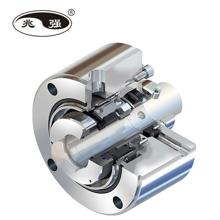
The Stein Seal® Company has developed API1 STANDARD 682 seals for the oil and gas industry. Stein Seal® has designed, manufactured and tested the seals according to the rigorous API Standard 682 test protocols. In general, these are balanced seals with cartridge construction. These seals are classified in to Types, Category, Arrangements and Configurations. The seals are designed and tested to operate continuously for 25,000 hours without need for replacements.
Type A seal is a balanced, internally-mounted, cartridge design, pusher seal with multiple springs. Secondary sealing elements are elastomeric O-rings.
Category 1 are intended for use in non API 610 pump seal chambers, meeting the dimensional requirements of ASME B 73.1 and ASME B73.2 seal chamber dimensions and their application is limited to seal chamber temperatures from -40°F to 500°F (-40°C ~ 260°C) and gauge pressures up to 300 psi (2 MPa / 20 bar).
Category 2 are intended for use in API 610 pump seal chambers dimensional requirements. Their application is limited to seal chamber temperatures from -40°F to 750°F (-40°C ~ 400°C) and gauge pressures up to 600 psi (4 MPa / 40 bar).
Category 3 provides the most rigorously tested and documented seal design. They meet the seal chamber envelope requirements of API 610 (or equal). Their application is limited to seal chamber temperatures from -40°F to 750°F (-40°C ~ 400°C) and gauge pressures up to 600 psi (4 MPa / 40 bar).
Arrangement 2 seals having two seals per cartridge assembly, utilizing the externally supplied buffer fluid at a pressure less than the seal chamber pressure.
Arrangement 3 seals having two seals per cartridge assembly, utilizing the externally supplied barrier fluid at a pressure higher than the seal chamber pressure.
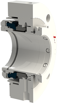
Face-to-back configuration – These seal are Arrangement 2 or 3 seals. In which one stationary face is mounted between two flexible rotary unit or one flexible rotary unit between two stationary face. The inner seal is OD pressurized by process fluid and barrier or buffer fluid is on the ID of the inner seal. The outer seal OD pressurized by barrier or buffer fluid.
Back-to-back configuration – These seal are Arrangement 2 or 3 seals. In which both the rotary faces are mounted between two stationary flexible units. The pumping fluid is on the ID of the inner seal, and the barrier (pressurized) or buffer (un pressurized) fluid is on the OD of the inner and outer seal.
Face-to-face configuration – These seal are Arrangement 2 or 3 seals. In which both the rotary faces are mounted between two flexible stationary units. The pumping fluid is on the ID of the inner seal, and the barrier (pressurized) or buffer (un pressurized) fluid is on the OD of the inner and outer seal.
A seal piping plan is designed, manufactured and supplied to improve the environment around the mechanical seal and therefore increase the performance and reliability of the seal. Piping plans range from very simple systems such as fluid recirculation into the seal chamber to complex systems which provide pressurization, cooling and circulation for support fluids and gases. The basic operation of the piping plan and also the requirements for instrumentation are followed as per API Standard 682 guidelines. Major piping plans supplied by Stein Seal® are Plan-21, Plan-23, Plan-32, Plan-52, Plan-53A, Plan-53B & Plan-53C.
Our API 682 seal design features, manufacturing capabilities and test facilities are witnessed and certified by a third party international certification organization. API 682 product offerings and capabilities can be found on our website www.steinseal.in
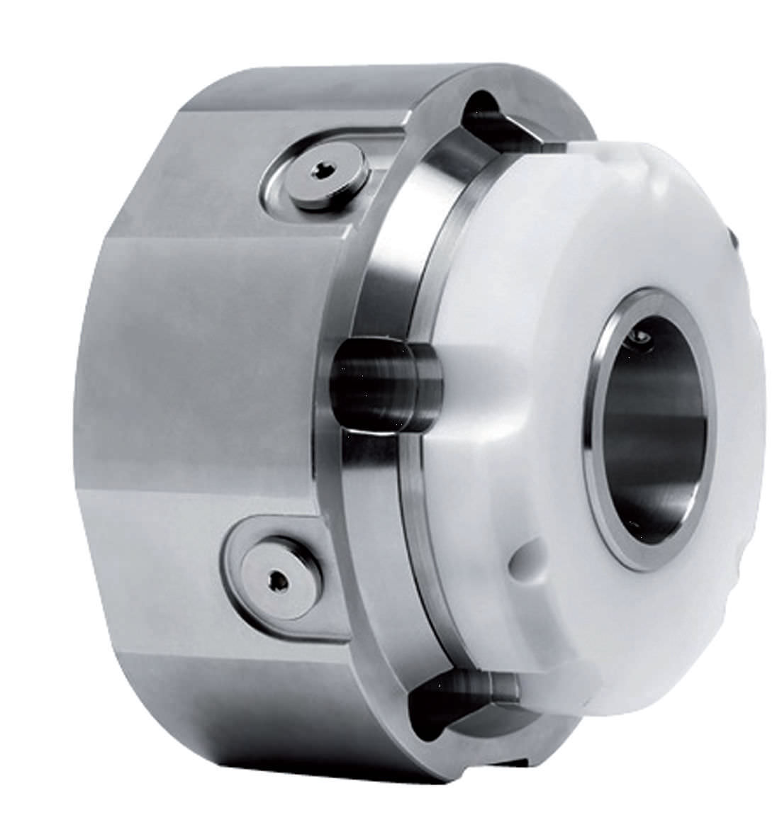
The AESSEAL® API Type A, B and C single-seal range offers the user an unprecedented range of API engineered sealing solutions to suit all application requirements. The category 1, 2 and 3 seals are qualification tested to API 682. Modular design allows the users to select the right solution for their application, with the modular design ensuring simplicity of purchase and fast delivery.
Thin cross-section (TXS) seal designs for mature asset installation including API 610, 5th Ed. with a 0.500" (12mm) radial cross-sectional space between the shaft and seal chamber
World-leading bi-directional pumping ring performance with 0.062” (1.5mm) radial clearance between rotor and stator; conforming with API 682 Section 8.6.2.3 without compromise
World-leading bi-directional pumping ring performance with 0.062” (1.5mm) clearance between rotor and stator, conforming with API 682 Section 8.6.2.3 without compromise
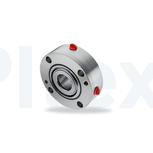
Also available CAPI-74 a face to face, category 2 & 3 seal. The CAPI-74 is a non-contacting dual seal designed for pumps meeting ANSI/API standard 682. Dual pressurized dry gas seals are becoming more common in the Oil and Gas industry and can provide zero process emissions in service. For more information visit the capi-74 product page

After more than five years of planning, the American Petroleum Institute (API) is preparing to release the 4th edition of API Standard 682 (ISO 21049:2011). The API 682 standard, which dates back to 1994 and is formally known as Shaft Sealing Systems for Centrifugal and Rotary Pumps, offers specifications and best practices for mechanical seals and systems to pump end users.
The standard’s latest edition began to take shape in 2006, when API formed a 4th edition task force to respond to end users’ questions and comments about previous editions. The task force soon realized that major changes, including reorganization and editing, would be necessary. While addressing every aspect of the resulting 4th edition (which is more than 250 pages long) would be impossible, this article summarizes the standard’s main points.
Those who use API 682 should understand the standard’s scope and remember that the standard does not include specifications for equipment outside that scope, such as engineered seals or mixers. Another important but often misunderstood point is that API 682’s figures are illustrative and not normative in their entirety.
For example, one of API 682’s figures shows a fixed throttle bushing combined with a rotating Type A seal, but seal manufacturers do not always have to combine these two components. The standard provides normative details in clauses and tables to help purchasers distinguish between requirements and suggestions.
The 4th edition continues to divide seals into three categories, three types and three arrangements. For all practical purposes, seal manufacturers can combine a seal’s component parts into nearly any orientation or configuration. Each orientation and configuration has advantages and disadvantages with respect to certain applications, performance and system disturbances.
Before the 4th edition, API 682 did not specify a minimum clearance between the inside diameter of a stationary seal part and the outside diameter of a rotating seal part. The 4th edition specifies this minimum clearance—typically the clearance between the sleeve and the mating ring. The specified clearances are representative of standard clearances that end users have used for decades. End users should not consider seal components to be “shaft catchers” to restrict shaft movement. The minimum clearance specified in API 682 also applies only to equipment within the standard’s scope. Equipment outside that scope, such as non-cartridge seals, older pumps, non-API 610 pumps and certain severe services, might benefit from larger clearances.
The new standard also updates the default bushings for the gland plate for the three seal categories. Fixed throttle bushings are now the default for Category 1 only, while floating bushings are the default for Categories 2 and 3.
While the 4th edition features the recommended seal selection procedure from the standard’s first three editions, it adds an alternative selection method in Annex A. Proposed by task force member Michael Goodrich, this alternative method recommends using material data sheet information to select a sealing arrangement.
Plans 66A and 66B are new to the standard, although end users have used them previously in pipeline applications. These plans detect and restrict excessive leakage rates in case of an Arrangement 1 seal failure.
The 4th edition has revised the data sheets in Annex C extensively to make them the same for all seal categories. Only two data sheets are included in the 4th edition—one in metric units and one in U.S. customary units. The new edition also folds Annex J into Annex E.
Previous editions of API 682 required metal plugs and anaerobic sealants when shipping new or repaired cartridges. After much debate, the task force decided that threaded connection points should be protected with plastic plugs for shipment. These plastic plugs should be red and have center tabs that operators can pull easily to distinguish the plugs from metal plugs. Shippers should also attach yellow warning tags to the plugs to indicate that end users need to remove the plugs before operation.
Although tutorial notes are scattered throughout API 682, this edition expands the tutorial section, Annex F, from seven pages to 42 pages. The expanded annex includes illustrative calculations. In particular, users interested in systems such as Plan 53B will find Annex F to be useful.
The 4th edition of API 682 is the product of more than 20 years of discussion, debate, usage and peer review. It includes a strong set of defaults and is by far the best and most logical starting point for mechanical seal and systems use. Equipment operators should take the time to familiarize themselves with API 682 to get the most out of this comprehensive standard.
Swagelok"s mechanical seal support systems are designed to maximize the life of mechanical seals and the reliability of rotating equipment by maintaining lubrication and system pressure and providing properly conditioned fluid flows.
Nearly 40%1 of all unscheduled critical pump shutdowns are caused by mechanical seal failures. While all seals leak, mechanical seals and mechanical seal support systems help control leakage, saving money, reducing labor, and improving safety. To protect your operations, it"s best to use a seal support system that is customized to your application"s specific needs and designed to reduce costly leak points.
Swagelok"sare guided by API 682 and designed to avoid pipe threads to limit the number of leak points wherever possible. Standardization is key in improving efficiency, and our customizable, repeatable design and assembly result in fast, efficient replacement, maximizing uptime. Where beneficial for system troubleshooting, maintenance, or safety, additional options are available to ensure the plan you choose fits your requirements.
Swagelok Swedenis your local source for API 682 mechanical seal support plans configured for your application. To help with labor, installation, and inventory costs,that bundle plan components are also available.
Our certified technicians undergo a comprehensive training and recertification program every three years to ensure your system is assembled to strict guidelines, providing you with reliable, consistent mechanical seal support systems.
The mechanical seal is the most likely part of the pump to fail. Approximately 70% of the pumps removed from service for maintenance are victims of mechanical seal failure. Mechanical seal parts are highly engineered with very close tolerances and any upset in the pump or associated system can cause seal failure, including:
Mechanical seals are based on positioning two very flat and smooth discs called seal faces, one rotating on the shaft and one stationary in the pump, against each other. The discs are flat and smooth enough to ALMOST prevent the pumped fluid from leaking out between them. However, the faces do rely on a very thin film of fluid between the faces to lubricate that rubbing fit. Without this film of fluid, the seals will overheat and fail. Lack of lubrication is the PRIMARY cause of seal failure. If the fluid is very hot, it can flash to a vapor as the fluid moves across the faces, again resulting in lack of lubrication. Note that gas seals use a gas film between the faces to minimize face contact and heat buildup.
Seal flush plans are intended to keep the area around the seal in the most seal friendly environment practical, usually meaning clean and cool. Dual seal plans also provide backup and leak detection for safety.
Note that seal flush plans use pressure differences at the pump to drive the flush fluids. The pump suction is low pressure, the seal chamber is a medium pressure, and the pump discharge is at high pressure.
As the seal faces faces rub together (with their thin film of lubricating fluid), they generate heat. The heat can build up in the seal chamber and push the fluid towards its boiling point, resulting in premature flashing, lack of lubrication, and failure. This first set of seal plans is intended to create circulation through the seal chamber to dissipate the heat out of the seal chamber and back into the pumped fluid.
Flush fluid flows from high pressure at pump discharge to the medium pressure seal chamber and back into the main flow to remove heat from seal chamber
Can be used to increase seal chamber pressure. Increased chamber pressure may be required to keep chamber fluid from flashing to vapor or to provide enough pressure to push the fluid between the faces for lubrication. (Seal chamber must be 5 psi minimum above external atmospheric pressure).
These seal plans are intended to provide the seal with the friendliest environment possible by cooling and/or cleaning the fluid in the seal chamber. The throat that separates the seal chamber from the main pumped fluid can be further restricted by adding a close clearance bushing in the bottom of the seal chamber, better isolating the cool, clean seal chamber fluid from the hot, abrasive fluid in the pump.
Rather than a Plan 21 single pass system, a Plan 23 is a multi-pass system. Fluid comes FROM THE SEAL CHAMBER instead of the pump discharge, is cooled, and directed back to the seal chamber.
Fluid is driven out of the chamber and through the cooler by “pumping ring” or other “pumping feature” built into the seal. These features provide very little differential pressure. Connecting tubing must have long, sweeping bends, well vented high points, and low point blowouts to ensure fluid flows.
Quench piping does NOT change conditions inside the seal chamber, at the wet side of the seal faces. Rather, it affects or monitors the environment on the ATMOSHPERIC side of the seal faces.
Pumps that leak when they are filled, even before they are started, often have a flush line intended for a Plan 11 or 13 connected to the QUENCH port, leading to the atmospheric side of the seal. There should be a “Q” or the work “QUENCH” stamped in the gland at this port.
For flush plans Plan 65A, 65B, 66A, and 66B, facility owners may want to know if their seals are leaking excessively without going to the expense of dual seals. These seal plans direct excessive leakage on the outside of the seal to an alarm instrument. Remember that seals leak a little bit. They need to in order to lubricate the faces and function correctly. The plans below handle the nuisance leakage in different ways.
Used in salting services like sodium hydroxide. The leakage across the seal faces will turn to salt when it reaches atmosphere. The salt crystals can wear the faces or build up in the seal, preventing the movement necessary to keep the seal faces in contact. The salt on the outboard of the seal can be washed away with a water quench through the quench and drain ports. Usually a close clearance bushing is installed at the extreme outboard end to the seal assembly to help keep the quench fluid moving from the quench to the drain port (or vice versa) and not just run out along the shaft. Also used for slurry services.
Grease can be introduced into the quench port. This external grease can provide temporary lubrication to the seal in case the pump sees large air or vapor pockets which would normally rob the seal faces of the required lubricating fluid film.
Quench can also be gas. In hot hydrocarbon services, the fluid will turn to solid coke when it reaches the atmospheric side of the seal. The fluid would remain a liquid if the area outside the seal faces is robbed of oxygen with a flood of nitrogen or steam.
An alarm does NOT necessarily mean a failed seal. The collection vessel might be full from years of nuisance leakage. Try emptying the vessel and observing how fast the vessel fills.
Two throttle bushings are used to ensure that the vapor (or fluid) leakage is limited along the shaft and out of the drain. A pressure switch picks up a rise on pressure above nuisance levels on the outboard side of the seal.
Dual seals provide a backup seal in case the primary seal fails. They prevent hazardous fluids from leaking to the surrounding area, desirable for both environmental protection and the safety of nearby personnel. Dual seals also capture and control any leakage of pumpage across the primary seal. The backup seal is kept lubricated by introducing a buffer/barrier fluid (often a mineral or synthetic oil, a water/glycol mix, or diesel) into the space between the primary (inboard) and secondary (outboard or backup) seals. The buffer/barrier fluid is contained in a tank (5 gallons is most common) adjacent to the pump. Instrumentation on the tank indicates what is happening with the seals.
Remember that a lubricating fluid film will flow from high pressure to low pressure. If the pump seal chamber pressure is higher than the pressure on the other side of the seal, the pumpage will be the lubricating film. If the pump’s seal chamber pressure is lower than the external pressure, the external atmosphere will migrate into the pump. Pumps under vacuum cannot use an ordinary single seal, since air from the atmosphere would be drawn between the faces, causing them to run dry and fail. Using a dual seal allows a fluid to be present at the outside of the seal. In a pump under vacuum, the buffer fluid would be pulled into the pump between the seal faces, keeping the inboard seal well lubricated.
If the pump seal chamber pressure is higher than the BUFFER fluid between the primary and backup seal faces, then the pumped fluid will flow from the high seal chamber pressure into the low pressure buffer fluid. This is called a DUAL UNPRESSURIZEDseal (formerly called a tandem seal), and the fluid is called a BUFFER fluid.
If the pump seal chamber pressure is lower than the BARRIER fluid between the primary and backup seal faces, then the barrier fluid will flow across the primary seal from the space between the primary and backup seals into the pump. This is called a DUAL PRESSURIZEDseal (formerly called a double seal), and the fluid is called a BARRIER fluid.
Buffer fluid circulates from the buffer fluid reservoir, through the space between the primary and backup seal, and back to the reservoir. Fluid is circulated by a weak pumping action built into the seal.
It the fluid flashes to vapor at low pressure, the vapor is piped to a flare or vapor recovery system, through an orifice at the top of the tank. If the primary seal is allowing too much leakage, the vapor will build pressure in the reservoir against the orifice and a pressure instrument can alert the operator.
If the fluid remains as a liquid under low pressure, any leakage will cause the fluid level in the buffer tank to rise, where a high level alarm can be tripped. Just because the high level alarm is tripped does not mean that the primary seal is failing; it is the rate of leakage filling the tank which matters. The high level may have been reached after collecting years of nuisance leakage. Often, an oil change to the original level is all that is required. Be sure the fluid is disposed of properly.
Seal face friction or hot pumpage can add heat to the buffer fluid. A cooling water coil is often installed in the reservoir to cool the buffer fluid.
Dual pressurized system (seal barrier fluid is at a higher pressure than the pump seal chamber). Pressurized systems are used to ensure that very dangerous fluids remain in the pump. The difference between 53A, 53B, and 53C is the method of pressurizing the barrier fluid. Pressure in the barrier fluid should be at least 10 psi over the pressure in the pump seal chamber.
Barrier fluid circulates from the barrier fluid reservoir, through the space between the primary and backup seal, and back to the reservoir. Fluid is circulated by a weak pumping action built into the seal.
A low level alarm in the reservoir alerts the operator that a seal may be failing, allowing the barrier fluid to enter the pump through the primary seal or the atmosphere through the backup seal.
Seal faces can be designed to maintain a gas film between them rather than a fluid film. These piping plans are intended to work with theses gas film (dry running) seals. Plan 72 and 74 bring the buffer or barrier gas into the seal; plans 75 and 76 are for the gas exiting the seal.
Secondary seal is ordinarily running with a gas film between the faces. When the primary seal fails, the pumped fluid will fill the space between the primary and backup seal. The backup seal is now working as a liquid seal rather than a gas seal and is designed to run for about 8 hours, allowing the operators time for an orderly pump shutdown.
Plan 72 buffer gas flow keeps the gas in the seal from becoming concentrated from nuisance leakage over time so that any leakage from the gas backup seal is mostly inert flush gas and not toxic pump vapors.
Pump Projects is your go-to resource for advice, sales and service for mechanical seals for pumps. We have the internal resources to help you with this complex issue.
A mechanical seal is simply a method of containing fluid within a vessel (typically pumps, mixers, etc.) where a rotating shaft passes through a stationary housing or occasionally, where the housing rotates around the shaft.


 8613371530291