
api plan 52 mechanical seal supplier
Circulation of buffer liquid to and from the reservoir is dependent on thermal siphoning and/or an internal circulating device (pumping ring) inside the seal.

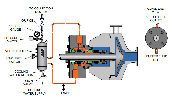
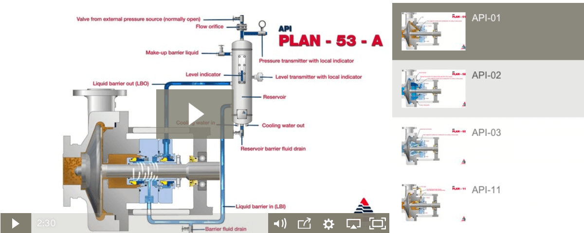
The MP52 series aligns with API 682 Plans 52 and 53A. The Plan 52 is designed to support liquid buffer fluid for a containment seal chamber that is below the seal chamber pressure. The Plan 53A is a pressurized system designed to isolate the seal from the process completely by providing liquid barrier fluid at a pressure higher than the seal chamber.
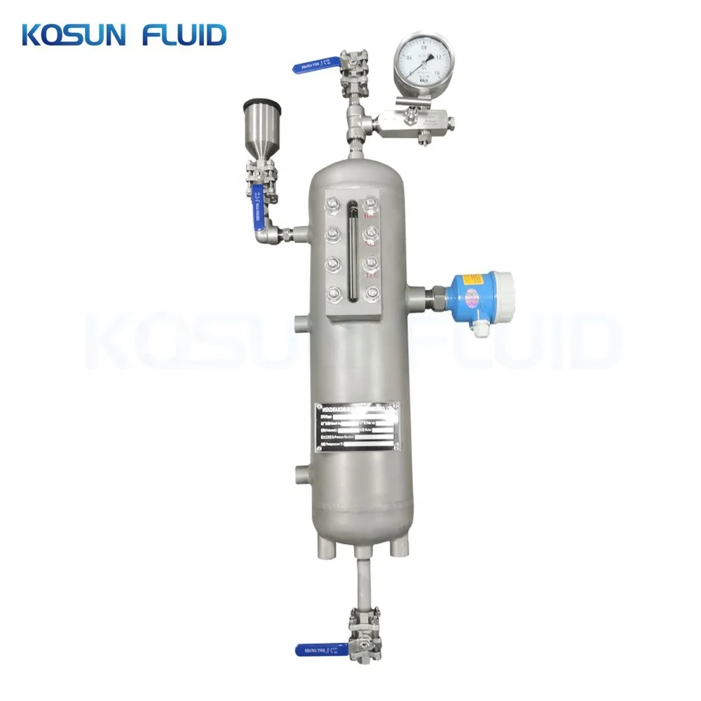
Our seal reservoirs are built to ASME Section VIII standards and are available with ASME U code stamps. Flexaseal Engineered Seals and Systems, LLC provides standard and custom buffer fluid reservoirs that meet API 682 Standards. As an industrial seal pot manufacturer for the chemical, petrochemical, and industrial industries, our seal pot systems help protect the environment and your workers from hazardous materials.
Depressurised buffer fluid circulation in outboard seal of a dual seal configuration through a seal support system. Circulation is maintained by using pumping ring in running condition and by thermosyphon effect in stand still condition.
1. Keep the sealant vessel vent continuously open, which is necessary to maintain buffer fluid pressure close to atmospheric pressure and vent the vapors to flare.

These reservoir-based seal support systems are designed for both API Plan 52 and 53A applications to support unpressurized and pressurized dual seals. Circulation of buffer/barrier fluid is normally achieved with a pumping ring (or optional circulating pump), and a range of heat exchangers can be packaged with the system — selection dependent on available plant utilities.

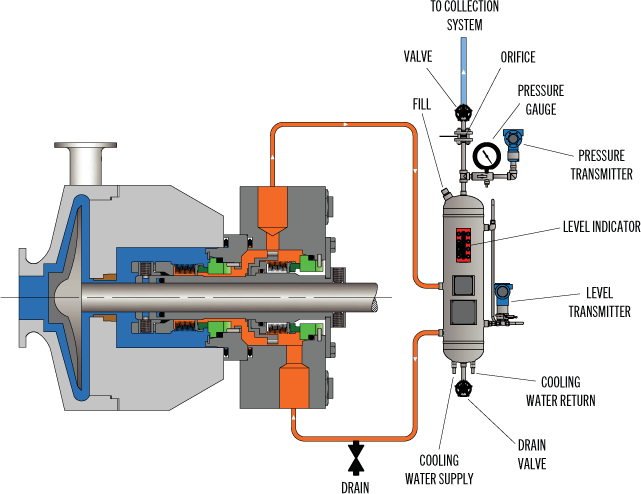
API Plan 52 utilizes a reservoir and circulates an unpressurized buffer fluid between the inboard and outboard seals. To provide positive circulation through the support system and into the seal, a pumping ring is employed. Frictional losses in the buffer fluid inlet and outlet lines should be minimized by selecting the proper tube size, using large radius and/or 45 degree bends, and reducing the length of tubing runs. Plan 52 is commonly used with light hydrocarbons or fluids with a high vapor pressure. The buffer fluid must be compatible with process fluid as inboard seal leakage will eventually mix with the buffer fluid.
Plan 52 is available as a seal pot assembly. The associated field installation kit for use in connecting the seal pot assembly to your system is also available. Assembly components may include:
See page 31 of the Mechanical Seal Support Systems Application Guide for additional details and ordering information. Contact your authorized Swagelok sales and service center for information on optional components.

Flowway Teknik design and manufactures seals and associated products mainly for the oil and gas, chemical, pharmaceutical, pulp and paper, power, mining and many more industrial applications. Today, it provides the most complete selection of engineered mechanical seals and sealing support systems. Our products are recognized as a trusted brand in a process industry.
In this plan external reservoir provides buffer fluid for the outer seal of an un-pressurized dual seal arrangement (Arrangement 2). During operation an internal pumping ring provides circulation. The reservoir is connected to a vapour recovery system and is maintained at a pressure less than the pressure in the seal chamber. It is normally used for the applications where process fluid leakage to atmosphere must be minimised and contained. Plan 52 works best with clean, non-polymerising pure products that have vapour pressure more than the buffer system pressure. Leakage of higher vapour pressure process liquid into buffer system will flash in the seal pot and escape into the vent system.
In this plan external reservoir provides buffer fluid for the outer seal of an un-pressurized dual seal arrangement (Arrangement 2). During operation an internal pumping ring provides circulation. The reservoir is connected to a vapour recovery system and is maintained at a pressure less than the pressure in the seal chamber. It is normally used for the applications where process fluid leakage to atmosphere must be minimised and contained. Plan 52 works best with clean, non-polymerising pure products that have vapour pressure more than the buffer system pressure. Leakage of higher vapour pressure process liquid into buffer system will flash in the seal pot and escape into the vent system.

You"re right, the friction of the seal faces will heat the buffer fluid, it can become quite hot. That being said, you still might not need to have cooling water or fins added to the reservoir or tubing.
Installation of the seal reservoir and tubing are of the utmost importance. Sight glasses, valves, narrow tubing, sharp bends in the tubing, and flowmeters should all be avoided. The tubing should be sloped at about 3 cm per meter back towards the seal, no high spots in the tubing, NONE. The fill line of the reservoir should be about a meter higher than the center line of the pump, and should be no further than about a meter from the seal. Your seal vendor should be able to provide literature with a nice diagram of an ideal installation.
The rotation of the seal will provide some windage to promote circulation of the buffer fluid, not much we"re talking a centemeter or so of head. Pumping rings provide a few cm of head and can be added to the seal, if not already installed. The temperature difference is what really drives the circulation of the buffer fluid. Your seal vendor might call this Thermosyphoning. The heat generated by the seal faces and the cooling effect of the tubing and the mass of the reservoir promote this. This is why minimal friction losses are important to the tubing installation. (generally pipefitters like to make thier work as neat as possible. do not allow them to tie the tubing to and from the seal together, keep the tubing lines apart so that they do not marginallize the temperature difference between them and reduce flow.)
Additionally, the way that the buffer fluid is added to the system can determine if the system will work. You must fill the reservoir and seal so that no air or vapor remains in the seal or tubing.
With an OEM pump package for an ANSI or DIN installation you"re likely to have a seal with connections on either side of the shaft. This works pretty well if you"re carefull about the way you add the buffer fluid. The connections are usually angled and called "tangential" ports. This is done again to reduce frictional losses in the system... it makes it easier for the buffer fluid to enter and leave the chamber in the seal. These connections do not make it easy to ensure that this chamber is liquid full. There may also be a connection at the top of the seal. Check the drawing provided with the seal to see if this port connects to the chamber between the two seals. If so, crack this port open when filling the seal letting the buffer fluid flow out of the seal along with the bubbles of air it"s displacing. When no more bubbles come out of the seal, it is full.
Some seals have connections at the top and bottom of the seal and do not angle the ports. This works well too, the seal "automatically" vents the air or vapor through the tubing. This can also be done with the standard ANSI or DIN seals by installing them 90 degrees off, as long as your bearing housing accomodates the tubing connections.
Be aware that the seal crack could have occured when a bubble of vapor finally budged allow flow to the seal... the cooler fluid suddenly hitting the hot seal faces could have caused thermal shock of a seal face.

The mechanical seal is the most likely part of the pump to fail. Approximately 70% of the pumps removed from service for maintenance are victims of mechanical seal failure. Mechanical seal parts are highly engineered with very close tolerances and any upset in the pump or associated system can cause seal failure, including:
Mechanical seals are based on positioning two very flat and smooth discs called seal faces, one rotating on the shaft and one stationary in the pump, against each other. The discs are flat and smooth enough to ALMOST prevent the pumped fluid from leaking out between them. However, the faces do rely on a very thin film of fluid between the faces to lubricate that rubbing fit. Without this film of fluid, the seals will overheat and fail. Lack of lubrication is the PRIMARY cause of seal failure. If the fluid is very hot, it can flash to a vapor as the fluid moves across the faces, again resulting in lack of lubrication. Note that gas seals use a gas film between the faces to minimize face contact and heat buildup.
Seal flush plans are intended to keep the area around the seal in the most seal friendly environment practical, usually meaning clean and cool. Dual seal plans also provide backup and leak detection for safety.
Note that seal flush plans use pressure differences at the pump to drive the flush fluids. The pump suction is low pressure, the seal chamber is a medium pressure, and the pump discharge is at high pressure.
As the seal faces faces rub together (with their thin film of lubricating fluid), they generate heat. The heat can build up in the seal chamber and push the fluid towards its boiling point, resulting in premature flashing, lack of lubrication, and failure. This first set of seal plans is intended to create circulation through the seal chamber to dissipate the heat out of the seal chamber and back into the pumped fluid.
Flush fluid flows from high pressure at pump discharge to the medium pressure seal chamber and back into the main flow to remove heat from seal chamber
Can be used to increase seal chamber pressure. Increased chamber pressure may be required to keep chamber fluid from flashing to vapor or to provide enough pressure to push the fluid between the faces for lubrication. (Seal chamber must be 5 psi minimum above external atmospheric pressure).
These seal plans are intended to provide the seal with the friendliest environment possible by cooling and/or cleaning the fluid in the seal chamber. The throat that separates the seal chamber from the main pumped fluid can be further restricted by adding a close clearance bushing in the bottom of the seal chamber, better isolating the cool, clean seal chamber fluid from the hot, abrasive fluid in the pump.
Rather than a Plan 21 single pass system, a Plan 23 is a multi-pass system. Fluid comes FROM THE SEAL CHAMBER instead of the pump discharge, is cooled, and directed back to the seal chamber.
Fluid is driven out of the chamber and through the cooler by “pumping ring” or other “pumping feature” built into the seal. These features provide very little differential pressure. Connecting tubing must have long, sweeping bends, well vented high points, and low point blowouts to ensure fluid flows.
Quench piping does NOT change conditions inside the seal chamber, at the wet side of the seal faces. Rather, it affects or monitors the environment on the ATMOSHPERIC side of the seal faces.
Pumps that leak when they are filled, even before they are started, often have a flush line intended for a Plan 11 or 13 connected to the QUENCH port, leading to the atmospheric side of the seal. There should be a “Q” or the work “QUENCH” stamped in the gland at this port.
For flush plans Plan 65A, 65B, 66A, and 66B, facility owners may want to know if their seals are leaking excessively without going to the expense of dual seals. These seal plans direct excessive leakage on the outside of the seal to an alarm instrument. Remember that seals leak a little bit. They need to in order to lubricate the faces and function correctly. The plans below handle the nuisance leakage in different ways.
Used in salting services like sodium hydroxide. The leakage across the seal faces will turn to salt when it reaches atmosphere. The salt crystals can wear the faces or build up in the seal, preventing the movement necessary to keep the seal faces in contact. The salt on the outboard of the seal can be washed away with a water quench through the quench and drain ports. Usually a close clearance bushing is installed at the extreme outboard end to the seal assembly to help keep the quench fluid moving from the quench to the drain port (or vice versa) and not just run out along the shaft. Also used for slurry services.
Grease can be introduced into the quench port. This external grease can provide temporary lubrication to the seal in case the pump sees large air or vapor pockets which would normally rob the seal faces of the required lubricating fluid film.
Quench can also be gas. In hot hydrocarbon services, the fluid will turn to solid coke when it reaches the atmospheric side of the seal. The fluid would remain a liquid if the area outside the seal faces is robbed of oxygen with a flood of nitrogen or steam.
An alarm does NOT necessarily mean a failed seal. The collection vessel might be full from years of nuisance leakage. Try emptying the vessel and observing how fast the vessel fills.
Two throttle bushings are used to ensure that the vapor (or fluid) leakage is limited along the shaft and out of the drain. A pressure switch picks up a rise on pressure above nuisance levels on the outboard side of the seal.
Dual seals provide a backup seal in case the primary seal fails. They prevent hazardous fluids from leaking to the surrounding area, desirable for both environmental protection and the safety of nearby personnel. Dual seals also capture and control any leakage of pumpage across the primary seal. The backup seal is kept lubricated by introducing a buffer/barrier fluid (often a mineral or synthetic oil, a water/glycol mix, or diesel) into the space between the primary (inboard) and secondary (outboard or backup) seals. The buffer/barrier fluid is contained in a tank (5 gallons is most common) adjacent to the pump. Instrumentation on the tank indicates what is happening with the seals.
Remember that a lubricating fluid film will flow from high pressure to low pressure. If the pump seal chamber pressure is higher than the pressure on the other side of the seal, the pumpage will be the lubricating film. If the pump’s seal chamber pressure is lower than the external pressure, the external atmosphere will migrate into the pump. Pumps under vacuum cannot use an ordinary single seal, since air from the atmosphere would be drawn between the faces, causing them to run dry and fail. Using a dual seal allows a fluid to be present at the outside of the seal. In a pump under vacuum, the buffer fluid would be pulled into the pump between the seal faces, keeping the inboard seal well lubricated.
If the pump seal chamber pressure is higher than the BUFFER fluid between the primary and backup seal faces, then the pumped fluid will flow from the high seal chamber pressure into the low pressure buffer fluid. This is called a DUAL UNPRESSURIZEDseal (formerly called a tandem seal), and the fluid is called a BUFFER fluid.
If the pump seal chamber pressure is lower than the BARRIER fluid between the primary and backup seal faces, then the barrier fluid will flow across the primary seal from the space between the primary and backup seals into the pump. This is called a DUAL PRESSURIZEDseal (formerly called a double seal), and the fluid is called a BARRIER fluid.
Buffer fluid circulates from the buffer fluid reservoir, through the space between the primary and backup seal, and back to the reservoir. Fluid is circulated by a weak pumping action built into the seal.
It the fluid flashes to vapor at low pressure, the vapor is piped to a flare or vapor recovery system, through an orifice at the top of the tank. If the primary seal is allowing too much leakage, the vapor will build pressure in the reservoir against the orifice and a pressure instrument can alert the operator.
If the fluid remains as a liquid under low pressure, any leakage will cause the fluid level in the buffer tank to rise, where a high level alarm can be tripped. Just because the high level alarm is tripped does not mean that the primary seal is failing; it is the rate of leakage filling the tank which matters. The high level may have been reached after collecting years of nuisance leakage. Often, an oil change to the original level is all that is required. Be sure the fluid is disposed of properly.
Seal face friction or hot pumpage can add heat to the buffer fluid. A cooling water coil is often installed in the reservoir to cool the buffer fluid.
Dual pressurized system (seal barrier fluid is at a higher pressure than the pump seal chamber). Pressurized systems are used to ensure that very dangerous fluids remain in the pump. The difference between 53A, 53B, and 53C is the method of pressurizing the barrier fluid. Pressure in the barrier fluid should be at least 10 psi over the pressure in the pump seal chamber.
Barrier fluid circulates from the barrier fluid reservoir, through the space between the primary and backup seal, and back to the reservoir. Fluid is circulated by a weak pumping action built into the seal.
A low level alarm in the reservoir alerts the operator that a seal may be failing, allowing the barrier fluid to enter the pump through the primary seal or the atmosphere through the backup seal.
Seal faces can be designed to maintain a gas film between them rather than a fluid film. These piping plans are intended to work with theses gas film (dry running) seals. Plan 72 and 74 bring the buffer or barrier gas into the seal; plans 75 and 76 are for the gas exiting the seal.
Secondary seal is ordinarily running with a gas film between the faces. When the primary seal fails, the pumped fluid will fill the space between the primary and backup seal. The backup seal is now working as a liquid seal rather than a gas seal and is designed to run for about 8 hours, allowing the operators time for an orderly pump shutdown.
Plan 72 buffer gas flow keeps the gas in the seal from becoming concentrated from nuisance leakage over time so that any leakage from the gas backup seal is mostly inert flush gas and not toxic pump vapors.

ATC ENSYS PVT LTD,as an ISO 9001: 2008 Certified companyfounded in2012 in Pune, is a leadingDesigners, Manufacturers ofEngineering oil & Gas Systems, LOS (Lube Oil System) as per API 614, Seal Auxiliary Systems like API Plans 52,53,53A,53B,53C, 72, 75, 76,and coolersas per API 682, pressure vessels, Air force cooler, etc.…
We are offering best quality engineering work and design as per international standards ASME and API for equipment built for use in oil, Gas and power generation plants.


 8613371530291