
api plan 52 mechanical seal factory
Depressurised buffer fluid circulation in outboard seal of a dual seal configuration through a seal support system. Circulation is maintained by using pumping ring in running condition and by thermosyphon effect in stand still condition.
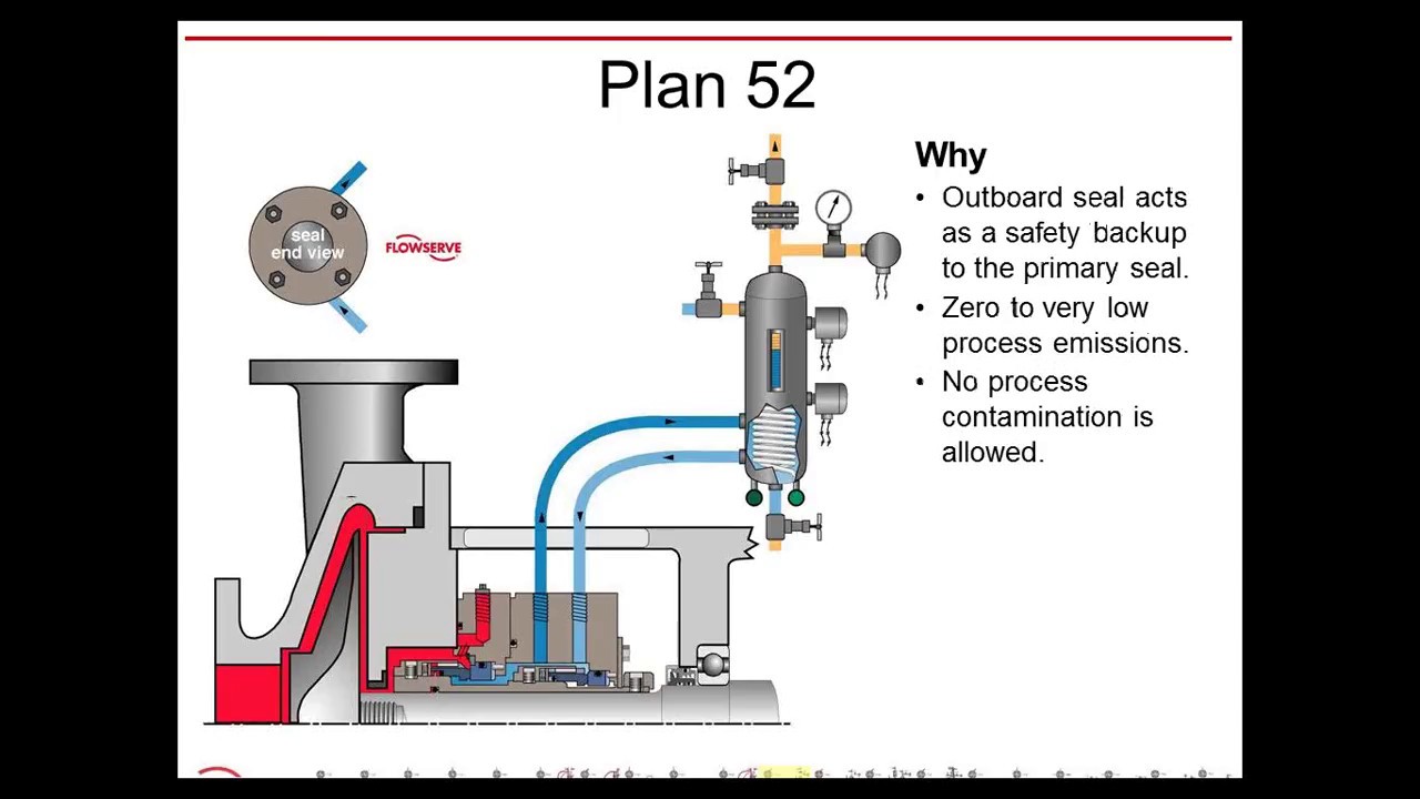
1. Keep the sealant vessel vent continuously open, which is necessary to maintain buffer fluid pressure close to atmospheric pressure and vent the vapors to flare.
Pumping processes involving hazardous or toxic fluids often utilize dual mechanical seals to ensure operator safety and compliance with environmental regulations. The American Petroleum Institute (API) Standard 682 classifies dual mechanical seals into two categories— pressured and unpressured. For unpressurized configurations, a seal flush system, such as API Plan 52, is required for the seal to operate. A buffer fluid is circulated between the inboard and outboard seals to form a “buffer” between the process fluid and environment.
API Plan 52 seal systems are the most commonly used pressurized dual mechanical seal flush systems in Canadian operations. Plan 52 is widely used in oil and gas operations, but can also be used in chemical and petrochemical refining and power generation applications. Let’s take a look into how the API Plan 52 seal system works for centrifugal pumps and applications in oil and gas, chemical and petrochemical refinement, and power generation.
API Plan 52 seal systems employ a seal pot (reservoir) to deliver an unpressurized buffer fluid to the seal chamber and circulate the fluid between the inboard and outboard mechanical seals. A pumping ring is utilized to provide positive circulation through the seal flush system and into the seal. This plan is commonly used with light hydrocarbons or fluids with a high vapour pressure.
In the event of an inboard seal failure, process fluid will leak into the seal chamber, mixing with the buffer fluid. Thus, the selected buffer fluid must be compatible with the process fluid. One challenge with this plan is frictional losses in the buffer fluid inlet and outlet lines. Frictional losses may be minimized through properly selecting tube size, using large radius and/or 45-degree bends, and reducing the length of tubing in the design.
Tubing configuration and geometry, materials of construction, buffer fluid type, and seal pot volume can be determined and configured based on specific pumping and mechanical seal requirements. API Plan 52 seal systems can include cooling coils within the reservoir to maintain the temperature of buffer fluid being delivered to the seal chamber. This plan can also include instrumentation, such as pressure transmitters, level transmitters, and thermometers depending on the given application. Fluid systems vendors should be consulted to determine configuration specifics such as those listed above.
Depending on the application of dual mechanical seal flush systems, there may be benefits in the higher standards of an ASME stamped seal pot as opposed to a seal pot that meets a lower piping standard. ASME stamped vessels can be more easily tracked and maintained through their Canadian Registration Number (CRN).
In oil and gas operations, including steam-assisted gravity drainage (SAGD), API plan 52 can be used for dual mechanical seals for centrifugal pumps in upstream, midstream, and downstream operations with either high vapour pressure or lower vapour pressure fluids. In chemical plants and petrochemical refineries, dual mechanical seals may be used for high vapour pressure fluid applications. For chemical plants where chemicals are extremely hazardous, a more robust sealing system may be implemented. For power generation, API Plan 52 may be used for water pumping applications, such as boiler feedwater pumps and water treatment pumps.
Whether you are looking to implement a new custom-configured API Plan 52 seal system—or you are looking to upgrade your current plan—Field Advisors at Edmonton Valve & Fitting can provide expert consultations to determine how to increase pumping reliability and efficiency. We are well-versed in local pumping applications for industries including oil and gas, chemical and petrochemical refining, and power generation. We also offer ASME stamped seal pots for customers who would like to ensure proper testing and maintenance tracking with a CRN.
To find out more about how Edmonton Valve & Fittingcan provide API Plan 52 seal systems equipped with ASME stamped seal pots, contact our team of advisorsthrough our website or by calling 780-437-0640.

API Seal Plan 52 utilizes a reservoir and circulates an unpressurized buffer fluid between the inboard and outboard seals. To provide positive circulation through the support system and into the seal, a pumping ring is employed. Frictional losses in the buffer fluid inlet and outlet lines should be minimized by selecting the proper tube size, using large radius and/or 45 degree bends, and reducing the length of tubing runs. Seal Plan 52 is commonly used with light hydrocarbons or fluids with a high vapor pressure. The buffer fluid must be compatible with process fluid as inboard seal leakage will eventually mix with the buffer fluid.
Plan 52 is available as a seal pot assembly. The associated field installation kit for use in connecting the seal pot assembly to your system is also available. Assembly components may include:
See page 31 of the Mechanical Seal Support Systems Application Guide for additional details and ordering information. Contact your authorized Swagelok sales and service center for information on optional components.
Circulation of buffer liquid to and from the reservoir is dependent on thermal siphoning and/or an internal circulating device (pumping ring) inside the seal.
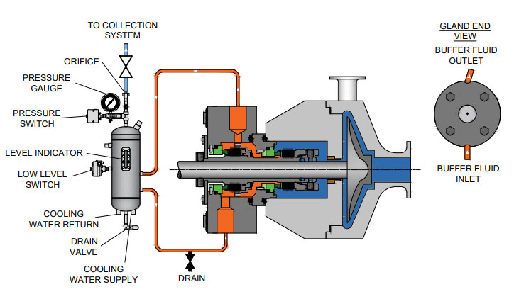
The MP52 series aligns with API 682 Plans 52 and 53A. The Plan 52 is designed to support liquid buffer fluid for a containment seal chamber that is below the seal chamber pressure. The Plan 53A is a pressurized system designed to isolate the seal from the process completely by providing liquid barrier fluid at a pressure higher than the seal chamber.
Our seal reservoirs are built to ASME Section VIII standards and are available with ASME U code stamps. Flexaseal Engineered Seals and Systems, LLC provides standard and custom buffer fluid reservoirs that meet API 682 Standards. As an industrial seal pot manufacturer for the chemical, petrochemical, and industrial industries, our seal pot systems help protect the environment and your workers from hazardous materials.
These reservoir-based seal support systems are designed for both API Plan 52 and 53A applications to support unpressurized and pressurized dual seals. Circulation of buffer/barrier fluid is normally achieved with a pumping ring (or optional circulating pump), and a range of heat exchangers can be packaged with the system — selection dependent on available plant utilities.

Flowway Teknik design and manufactures seals and associated products mainly for the oil and gas, chemical, pharmaceutical, pulp and paper, power, mining and many more industrial applications. Today, it provides the most complete selection of engineered mechanical seals and sealing support systems. Our products are recognized as a trusted brand in a process industry.

Flowway Teknik design and manufactures seals and associated products mainly for the oil and gas, chemical, pharmaceutical, pulp and paper, power, mining and many more industrial applications. Today, it provides the most complete selection of engineered mechanical seals and sealing support systems. Our products are recognized as a trusted brand in a process industry.

Conclusion of our series covering applications in which they are used, why they are used, how they fail and things operators can check/do to maintain the performance of the seal flush plan.
Plan 52 uses an external reservoir to provide buffer fluid for the outer seal of an unpressurized dual seal arrangement. During normal operation, circulation is maintained by an internal pumping ring. The reservoir is usually continuously vented to a vapor recovery system and is maintained at a pressure that is usually at or near atmospheric pressure. The inner process seal of the dual unpressurized arrangement usually has its own flush plan.
For example, Plan 11 might be used on the inner seal along with Plan 52 for the outer seal. In such cases, the complete flush plan might be described as Plan 11/52. The reservoir size can range from two gallons to 5+ gallons of liquid capacity and has an internal coil of tubing which is used to remove heat.
The circulation rate within a Plan 52 depends on the performance of the pumping ring within the particular closed loop system. The reservoir size is selected based on the size of the seal and the pump shaft speed. Small ANSI pumps typically have the smaller 2-gal reservoir. Larger pumps may require larger reservoirs, especially at elevated pumping temperatures. Heat soak, seal generation heat along with turbulence energy within the outer seal chamber, must be considered in determining the desired circulation rate.
The general rule of thumb is that the reservoir should be located within a plot plan radius of about 3-ft, with the bottom of the reservoir 18-in to 30-in above the centerline of the pump. Many customers require that the liquid level provide at least 3-ft of static head to the outer seal.
In the event that the process, or inner, seal fails, there will be a pressure and/or level increase in the reservoir to set off an alarm. When this occurs, the reservoir should be blocked in by closing the valve near the top of the reservoir. As the process seal continues to leak, pressure and fluid level in the reservoir continues to increase. The reservoir can potentially reach the same pressure as the process seal chamber.
For all practical purposes, the outer seal takes over as the primary seal. For this reason, the recommended operating procedure is to begin planning an orderly shutdown for seal replacement as soon as possible after failure of the process seal.
In the past, most reservoirs for Plan 52 were vented to atmosphere, but due to environmental concern most systems are piped to a vapor recovery system. Plan 52 is used for both non-volatile and volatile process services. Although the leakage rate across the inboard seal is the roughly the same as for a single seal, the leakage is directed into the reservoir of the dual unpressurized seal system.
In non-volatile services the leakage from the process seal increases the liquid level in the reservoir. In volatile services, the leakage from the process seal vaporizes and rises to the top air space inside the reservoir. When the reservoir is connected to a vapor recovery system, the actual emission rate can be very low.
Plan 52 is a necessity for dual unpressurized seals using a liquid buffer fluid. In comparison to single seals, the dual unpressurized seal can provide reduced net leakage rates as well as redundancy in the event of a main seal failure.
There will always be some leakage from the process seal into the buffer system where the buffer fluid is contaminated by the process fluid. Thus, buffer fluids must be selected with great care. It is possible over time that heavier process fluids will displace the buffer fluid resulting in the outer seal to be sealing the process fluid, thereby losing a buffer between the product and atmosphere.
If the process fluid has a low vapor pressure margin, the heat from the outer seal can further reduce the margin causing the inboard seal to run with partial to full vapor between the sealing faces so an alternate system with dry running containment seals would be the recommendation.
In the past there was only one Plan 53, but with the 2nd Edition of API 682 and the 1st Edition of ISO 21049 other variations of Plan 53"s were created.
Plan 53A is the former Plan 53. Plan 53B is what had been in the past denoted as Plan 53 Modified; this is especially popular in European and other countries in the Middle East. Plan 53C is a variation of this that has also been used in the past and is now formally recognized.
The major difference in the plans is that Plan 53A uses an external reservoir, while Plans 53B and 53C run within a closed loop system with a make-up system piped to it for replenishment of the barrier fluid.
In dual pressurized sealing arrangements the inner process seal can have its own flush plan; in such applications the complete flush plan system designation should include both plans. For example, Plan 11/53A means that the inner seal has its own flush plan, Plan 11. The API/ISO default is for no separate flush plan when using any of the Plan 53"s, but this can vary with the application conditions.
With the older traditional back-to-back seal arrangement the inboard seal usually does not require a separate flush. In applications such a hydrofluoric acid, where it is both extremely hazardous and corrosive, a Plan 32 can be used in conjunction with a Plan 53. The dual pressurized face-to-back seal arrangement eliminates some of the potential problems associated with the back-to-back design. This face-to-back seal arrangement sometimes incorporates a reverse pressure capability that is not a default with the back-to-back design.
Also, face-to-back arrangements do not have a dead zone underneath the inboard seal that can become clogged by dirty process fluid and lead to seal hang-up. However, the face-to-back arrangement is not a cure-all. With the product on the seal O.D. and with it being used on API pumps that still incorporate throat bushings, it is advantageous to provide a flush for the inboard seal on a number of applications.
Abrasives can accumulate in the more closed API type seal chambers compared to the newer generation chemical duty pumps with large cylindrical bore or tapered bore chambers. The use of a Plan 11 or similar bypass type flush for the inner seal has advantages. It can help keep the seal chamber clean. It also has an improved overall heat transfer setup versus just using a Plan 53 system alone.
In comparison to a Plan 54, Plans 53A/B/C are usually less complex and less expensive. With Plans 53A/B/C, both the inner and the outer seals are lubricated by the barrier fluid, which can be selected for optimum seal performance. Plans 53A/B/C are usually selected for dirty, abrasive, or polymerizing process services which might be difficult to seal directly with single seals or with dual unpressurized seals using a Plan 52. There will always be some leakage of the barrier fluid into the process with any pressurized system.
With some of the Plan 53 systems the volume of barrier fluid is limited, especially compared to a Plan 54 system. Venting of the seal chamber is essential for all Plan 53"s where vapor locking can if vapor bubbles collect near the pumping ring or in the piping.
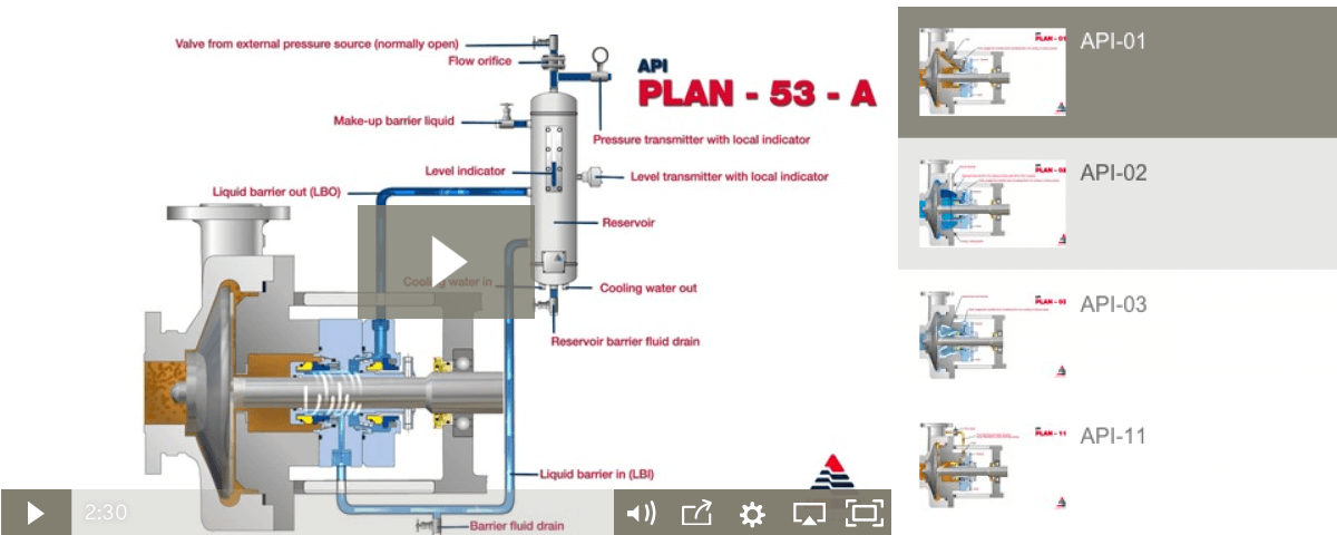
Plan 53A uses an external reservoir to provide barrier fluid for a pressurized dual seal arrangement. Reservoir pressure is produced by a gas, usually nitrogen, at a pressure greater than the maximum process pressure being sealed. The gas pressure is regulated by a system that is outside the schematic of the piping plan. Circulation of the barrier fluid is maintained by an internal pumping ring.
Like Plan 52 reservoirs, cooling is accomplished internal coil of tubing to remove the heat. Also like Plan 52 reservoirs, the volume of barrier liquid can vary from two gallons to 5+ gallons, where API and ISO standards specify 3-gal and 5-gal, depending upon the shaft diameter.
For non-API specifications, smaller reservoirs - typically 2-gal - are often used, especially at ambient pumping temperatures. Pressure alarms, pressure gages and level switches are typically standard equipment and are required by API 682/ISO 21049.
The circulation rate in a Plan 53A system is like a Plan 52 system described earlier. The piping to and from the seal chamber and location of the reservoir is also the same as a Plan 52 system. Unlike Plan 52, the elevation of the reservoir does not contribute to the pressure in the sealing cavity.
The usual guideline for Plan 53 barrier pressures is that they be a minimum of 20-psi to 50-psi above the maximum process pressure seen by the seal. Barrier pressure is normally supplied by a plant wide distribution system. Nitrogen bottles should not be used as they require a lot of attention and maintenance.
API 682/ISO 21049 recommends that the system be limited to 150-psig due to gas entrainment into the barrier fluid. Field experience has shown that with the proper barrier fluid, Plan 53A systems can be used up to 300-psig if the temperature is controlled to less than 250-deg F. A variation to this would be to use an accumulator to eliminate gas entrainment.
The barrier fluid in Plan 53A is subject to gas entrainment due to direct exposure to the pressurizing gas. Different barrier fluids have varying levels of gas entrainment.
Installation should be limited to a single seal installation even on between bearing pumps. Therefore for a large number of installations, Plan 53A can be more expensive than Plan 53B or 53C.
Unlike a Plan 53A that incorporates a pressurized reservoir within the circulation loop, Plan 53B incorporates a bladder type accumulator along with the piping and an air or water cooled heat exchanger to provide for barrier fluid capacity.
Some installations use finned tubing as the heat exchanger, but these should be used with caution as the heat removal depends upon a positive air flow across the tubing to be effective. Gas entrainment is not a problem with this plan since it incorporates bladder accumulator to maintain the barrier pressure within the closed loop circuit.
The accumulator should be pre-pressurized to between 80 percent and 90 percent of the barrier pressure. This creates a problem in that it limits the volume of fluid within the Plan 53B circuit. The majority of the accumulator volume is gas. The basic setup is comprised of two parts; the closed loop circulating system made up of the piping and heat exchanger and the make up system.
Flow in the circulating system is usually induced by an internal pumping device. The make up system can be configured a number of ways based upon the customer"s preference, ranging from a simple hand pump to an elaborate pumping system feeding multiple pumps/seals.
Like Plan 53A, the flow rate of the Plan 53B circuit is controlled by the pumping ring design, peripheral speed, barrier fluid viscosity, and resistance of the piping circuit; the piping circuit of 53B includes a heat exchanger. The sizing of the heat exchanger depends upon the heat load of the system. The heat exchanger should be designed to contribute minimum resistance.
API 682, 3rd edition does not provide guidelines for sizing the accumulator of Plan 53B, but the total fluid volume of the system should be about the same as the volume of a 53A system.
With the limited fluid volume the barrier fluid gets thermally cycled on a much more frequent basis than a Plan 53A, so the service life of the fluid is reduced.
The finite volume of the accumulator requires a designed pressure operating range between refills (in excess of that required for a Plan 53A) and this must be built into the pressure rating of the seals.
The separate heat exchanger introduces additional flow resistance to the piping system and will have a lower flow rate than an otherwise identical Plan 53A.
Plan 53C is a variation of Plan 53B that uses a piston accumulator to track the pressure of the seal chamber. In Plan 53C, the piston accumulator has a reference line from the seal chamber to the bottom of the accumulator. There are differences in diameter of the internal piston so that a higher pressure is generated on the top half, which in turn is piped to the circuit loop into and out of the seal chamber.
Similar to Plan 53B, there is no gas pressurizing the barrier fluid so there is no chance of gas entrainment. Also, like Plan 53B flow is generated by a pumping ring through a heat exchanger. The heat exchanger can be water cooled, air cooled or can be finned tubing if the heat load is small enough. This system should be used with caution, as the reference line to the accumulator is subject to the process fluid. The process fluid may be corrosive, abrasive, or a slurry that could potentially clog the pressure reference line threatening the tracking ability of the system.
The advantages and disadvantages are the same as the Plan 53B system. Additionally, the disadvantage of this system is that pressure spikes or pressure drops in the process pressure will vary the pressure on the outer seal that may create a temporary leakage condition. Also, tracking pressures can always be subject to delays that can cause a temporary loss of positive pressure differential across the inboard seal.
Plan 54 utilizes an external source to provide a clean pressurized barrier fluid to a dual pressurized seal. Strictly speaking, there is no "Plan 54 System" specified by API. That is, the details of the external lubrication system are not included by simply specifying Plan 54.
The external lubrication system for Plan 54 can be as simple as a basic reservoir, pump/motor, heat exchanger and relief valves to a complex system per API Standard 614 system. Plan 54 can even be pressurized from a process stream (the so-called "Process Plan 54").
The flush rate for a Plan 54 system must take into account not only energy from the mechanical seal (heat soak, seal generated heat, and turbulence), but also the heat added to the barrier fluid from the pump supplying the barrier fluid. On low pressure/flow systems this is minimal, but can become significant on larger systems operating at high pressures and flows.
The system reservoir should be sized for a retention time of 5 minutes, so if the flow rate is 4-gpm the reservoir size should be a minimum of 20-gal. The flow rate is usually controlled by the size of the pump on the system. In applications where one system is supplying barrier fluid to multiple seal chambers, flow can be controlled with simple manually adjustable needle or globe valves to control valves utilizing a variety of mechanical or pneumatic systems.
Like other pressurized systems, the barrier pressure should be above the maximum pressure that the inboard seal will be subject to. This differential can range from a minimum of 25-psi to large differentials to account for possible upset conditions.
The barrier fluid is typically one that has good to exceptional lubricating properties, that when applied properly can result in extended MTBPM for the seal.
The mechanical seal is exposed to a neutral fluid, with the exception of parts of the inboard seal, so that corrosion and other chemical related problems are eliminated.
If used on multiple seal installations, the failure of one can have an effect on all of the other installations unless proper precautions are taken to isolate the failed seal.
Plan 72 uses an external low pressure buffer gas, usually nitrogen, which is regulated by a control panel before it is injected into the outer seal cavity of a dual unpressurized seal arrangement. It is almost always used in conjunction with either a Plan 75 or Plan 76 to lead inboard seal leakage to a collection system.
The control panel should contain a pressure control valve to limit buffer gas pressure in order to prevent reverse pressure on the inboard seal and/or limit pressure applied to the secondary containment seal. This is followed by either an orifice or needle valve to control the gas flow rate. The control panel should also have a coalescing filter to prevent solids and/or liquids within the buffer gas from contaminating the secondary containment seal.
A very important feature of this plan is that the gas purge is introduced close to the seal faces, whereas the vent and drain are located away from the seal faces. In API 682/ISO 21049 a bushing is required to physically separate the buffer inlet and the vent/drain. Plan 72/75 is used for primary seal leakage that is condensing (returning to liquid form). Plan 72/76 is used for non-condensing (vapor) leakage. This helps to minimize process fluid from affecting the containment seal faces and aids in diluting leakage to the atmosphere.
It is recommended that a Plan 72 not be used in a dead-ended containment chamber. The gas pressure regulator should control the pressure upstream of the flow control system to slightly less than the Plan 75 or 76 alarm setting to ensure buffer flow over the complete system operational range.
The minimum gas flow rate for dry containment seals should be in the 3-scfh to 6-scfh range, which will provide adequate product leakage dilution at normal inboard leak rates. Gas flow rates at this level can only be controlled by a needle valve. If dilution is still required at Plan 75 or 76 alarm points and/or a flow control orifice is specified by the purchaser, buffer gas flow rates are likely to be in excess of 20-scfh.
Contacting containment seals run better with the moisture from the process vapor leakage. A dry nitrogen purge reduces the moisture in the containment seal chamber and can decrease the operating life of the containment seal.
Plan 74 is a pressurized plan for dual gas seals that utilizes an inert gas, typically nitrogen, as the barrier fluid. As with all pressurized dual seal arrangements, the barrier fluid is at a pressure greater than the process pressure being sealed.
Dual gas seals differ from other pressurized dual seal arrangements in that they do not require circulation of a fluid between the seals since the seal generated heat is minimal. The flow of inert gas is the result of leakage past the outboard seal faces and, to a lesser extent, the inboard seal faces due to the low differential between the barrier pressure and process pressure.
As with the Plan 53A system, the inert gas normally is supplied by a plant wide distribution system. In some very special cases the nitrogen source can be a bank of nitrogen bottles. However, this can be an expensive, unreliable system, and the maintenance is high to ensure that the bottles have sufficient pressurized gas at all times.
Plan 74 includes a control panel to regulate the pressure going to the dual gas seals and API 682 includes some details of the panel. The panel also acts to remove moisture and filter the inert gas. The panel should contain a low pressure alarm along with flow meters. Flow alarms warn against problems with the gas supply and are optional.
The nitrogen source in a typical plant has pressure on the order of 100-psig. If the dual gas seal is sealing product pressures in excess of 75-psig, then the typical plant nitrogen gas source alone may be inadequate. In these applications a pressure amplifier (piston pump) can be utilized to boost system pressure.
The high pressure gas from the booster should be fed into a receiver of suitable capacity, as piston pumps are not designed for continuous operation. For this reason it is advisable to oversize the piston pump to minimize its operation and prolong maintenance cycles. It is not recommended to just hook the inert gas line directly to the seal cartridge. This is very unreliable, prevents regulation of pressure, and can allow for contamination of the seal faces that results in seal performance problems.
The schematic for Plan 74 shows two connections, a gas barrier inlet and outlet. The outlet is normally plugged as flow beyond makeup for seal leakage is typically not a requirement for these seals.
Plan 75 is designed for use with a dual unpressurized seal utilizing a dry running containment seal, where primary seal leakage is collected into a reservoir. It is intended to be used when the process sealed by the primary seal will condense to a liquid at lower temperatures or is always in a liquid form.
In this arrangement, the drain is located at the bottom of the outer seal gland and is routed to the reservoir. Liquid leakage is collected in the reservoir and the gaseous portion is further routed through an orifice to a flare or vapor recovery system.
The reservoir does contain a pressure gauge and a high pressure switch to indicate a buildup in pressure in the reservoir from excessive primary seal gaseous leakage or a primary seal failure of some magnitude. Some users prefer to isolate the secondary containment device with valves to the reservoir in the event of a primary seal failure. A level switch to warn of excessive liquid leakage is optional on the reservoir.
The secondary containment seal can be subject to clogging in this arrangement. Some sort of baffle or close clearance bushing between the seal and gland should be used to isolate the containment seal from the leakage of the primary seal per API 682/ISO 21049. As noted earlier, Plan 75 can be used in conjunction with a gas purge from Plan 72. Typically, contacting secondary containment seals are used with this plan.
Plan 76 is designed for use with a dual unpressurized seal utilizing a dry running containment seal, where primary seal leakage is piped to a flare or vapor recovery system. It is intended to be used when the process sealed by the primary seal will not condense to a liquid at lower temperatures or pressures.
In this arrangement, the vent connection is located at the top of the outer seal gland for routing the vapors through an orifice that would create a back pressure to exist in the event of high inboard seal leakage. A pressure gauge and a high pressure alarm indicates this condition. API requires a minimum orifice diameter of .125-in, but smaller sizes may be necessary to provide a realistic leakage alarm point. It is recommended that the high pressure alarm switch be set at 7-psi above the mean operating condition in the flare or vapor recovery system.
The piping should continuously rise from the vent to the piping/instrument harness and should be properly supported so as not to impart strain to the gland. A drain connection in the piping is advisable in order to safely dispose of process fractions that may have condensed. A block valve is standard on this arrangement, to isolate the containment seal in the event of a primary seal failure.
While the secondary containment seal is less subject to clogging in this arrangement, the leakage from the primary seal may be a combination of a condensing and non-condensing fluid. When this is the case, the addition of a Plan 72/76 is highly recommended.
Heat generated by secondary containment seals is small compared to contacting wet seals so minimal heat is added to the inboard seal. This is important in applications where the vapor pressure margin for the inboard seal is critical.
The secondary containment seal can become clogged with debris if the primary seal leakage contains a heavy fluid that can coke or crystallize upon exposure to air. This can be improved upon through the use of Plan 72 and a bushing that directs the fluid away from the seal and seal faces.
Should some of the primary seal leakage condense and accumulate in the seal chamber, the containment seal will generate more heat that can potentially cause coking of the product and shorten seal life.

The mechanical seal is the most likely part of the pump to fail. Approximately 70% of the pumps removed from service for maintenance are victims of mechanical seal failure. Mechanical seal parts are highly engineered with very close tolerances and any upset in the pump or associated system can cause seal failure, including:
Mechanical seals are based on positioning two very flat and smooth discs called seal faces, one rotating on the shaft and one stationary in the pump, against each other. The discs are flat and smooth enough to ALMOST prevent the pumped fluid from leaking out between them. However, the faces do rely on a very thin film of fluid between the faces to lubricate that rubbing fit. Without this film of fluid, the seals will overheat and fail. Lack of lubrication is the PRIMARY cause of seal failure. If the fluid is very hot, it can flash to a vapor as the fluid moves across the faces, again resulting in lack of lubrication. Note that gas seals use a gas film between the faces to minimize face contact and heat buildup.
Seal flush plans are intended to keep the area around the seal in the most seal friendly environment practical, usually meaning clean and cool. Dual seal plans also provide backup and leak detection for safety.
Note that seal flush plans use pressure differences at the pump to drive the flush fluids. The pump suction is low pressure, the seal chamber is a medium pressure, and the pump discharge is at high pressure.
As the seal faces faces rub together (with their thin film of lubricating fluid), they generate heat. The heat can build up in the seal chamber and push the fluid towards its boiling point, resulting in premature flashing, lack of lubrication, and failure. This first set of seal plans is intended to create circulation through the seal chamber to dissipate the heat out of the seal chamber and back into the pumped fluid.
Flush fluid flows from high pressure at pump discharge to the medium pressure seal chamber and back into the main flow to remove heat from seal chamber
Can be used to increase seal chamber pressure. Increased chamber pressure may be required to keep chamber fluid from flashing to vapor or to provide enough pressure to push the fluid between the faces for lubrication. (Seal chamber must be 5 psi minimum above external atmospheric pressure).
These seal plans are intended to provide the seal with the friendliest environment possible by cooling and/or cleaning the fluid in the seal chamber. The throat that separates the seal chamber from the main pumped fluid can be further restricted by adding a close clearance bushing in the bottom of the seal chamber, better isolating the cool, clean seal chamber fluid from the hot, abrasive fluid in the pump.
Rather than a Plan 21 single pass system, a Plan 23 is a multi-pass system. Fluid comes FROM THE SEAL CHAMBER instead of the pump discharge, is cooled, and directed back to the seal chamber.
Fluid is driven out of the chamber and through the cooler by “pumping ring” or other “pumping feature” built into the seal. These features provide very little differential pressure. Connecting tubing must have long, sweeping bends, well vented high points, and low point blowouts to ensure fluid flows.
Quench piping does NOT change conditions inside the seal chamber, at the wet side of the seal faces. Rather, it affects or monitors the environment on the ATMOSHPERIC side of the seal faces.
Pumps that leak when they are filled, even before they are started, often have a flush line intended for a Plan 11 or 13 connected to the QUENCH port, leading to the atmospheric side of the seal. There should be a “Q” or the work “QUENCH” stamped in the gland at this port.
For flush plans Plan 65A, 65B, 66A, and 66B, facility owners may want to know if their seals are leaking excessively without going to the expense of dual seals. These seal plans direct excessive leakage on the outside of the seal to an alarm instrument. Remember that seals leak a little bit. They need to in order to lubricate the faces and function correctly. The plans below handle the nuisance leakage in different ways.
Used in salting services like sodium hydroxide. The leakage across the seal faces will turn to salt when it reaches atmosphere. The salt crystals can wear the faces or build up in the seal, preventing the movement necessary to keep the seal faces in contact. The salt on the outboard of the seal can be washed away with a water quench through the quench and drain ports. Usually a close clearance bushing is installed at the extreme outboard end to the seal assembly to help keep the quench fluid moving from the quench to the drain port (or vice versa) and not just run out along the shaft. Also used for slurry services.
Grease can be introduced into the quench port. This external grease can provide temporary lubrication to the seal in case the pump sees large air or vapor pockets which would normally rob the seal faces of the required lubricating fluid film.
Quench can also be gas. In hot hydrocarbon services, the fluid will turn to solid coke when it reaches the atmospheric side of the seal. The fluid would remain a liquid if the area outside the seal faces is robbed of oxygen with a flood of nitrogen or steam.
An alarm does NOT necessarily mean a failed seal. The collection vessel might be full from years of nuisance leakage. Try emptying the vessel and observing how fast the vessel fills.
Two throttle bushings are used to ensure that the vapor (or fluid) leakage is limited along the shaft and out of the drain. A pressure switch picks up a rise on pressure above nuisance levels on the outboard side of the seal.
Dual seals provide a backup seal in case the primary seal fails. They prevent hazardous fluids from leaking to the surrounding area, desirable for both environmental protection and the safety of nearby personnel. Dual seals also capture and control any leakage of pumpage across the primary seal. The backup seal is kept lubricated by introducing a buffer/barrier fluid (often a mineral or synthetic oil, a water/glycol mix, or diesel) into the space between the primary (inboard) and secondary (outboard or backup) seals. The buffer/barrier fluid is contained in a tank (5 gallons is most common) adjacent to the pump. Instrumentation on the tank indicates what is happening with the seals.
Remember that a lubricating fluid film will flow from high pressure to low pressure. If the pump seal chamber pressure is higher than the pressure on the other side of the seal, the pumpage will be the lubricating film. If the pump’s seal chamber pressure is lower than the external pressure, the external atmosphere will migrate into the pump. Pumps under vacuum cannot use an ordinary single seal, since air from the atmosphere would be drawn between the faces, causing them to run dry and fail. Using a dual seal allows a fluid to be present at the outside of the seal. In a pump under vacuum, the buffer fluid would be pulled into the pump between the seal faces, keeping the inboard seal well lubricated.
If the pump seal chamber pressure is higher than the BUFFER fluid between the primary and backup seal faces, then the pumped fluid will flow from the high seal chamber pressure into the low pressure buffer fluid. This is called a DUAL UNPRESSURIZEDseal (formerly called a tandem seal), and the fluid is called a BUFFER fluid.
If the pump seal chamber pressure is lower than the BARRIER fluid between the primary and backup seal faces, then the barrier fluid will flow across the primary seal from the space between the primary and backup seals into the pump. This is called a DUAL PRESSURIZEDseal (formerly called a double seal), and the fluid is called a BARRIER fluid.
Buffer fluid circulates from the buffer fluid reservoir, through the space between the primary and backup seal, and back to the reservoir. Fluid is circulated by a weak pumping action built into the seal.
It the fluid flashes to vapor at low pressure, the vapor is piped to a flare or vapor recovery system, through an orifice at the top of the tank. If the primary seal is allowing too much leakage, the vapor will build pressure in the reservoir against the orifice and a pressure instrument can alert the operator.
If the fluid remains as a liquid under low pressure, any leakage will cause the fluid level in the buffer tank to rise, where a high level alarm can be tripped. Just because the high level alarm is tripped does not mean that the primary seal is failing; it is the rate of leakage filling the tank which matters. The high level may have been reached after collecting years of nuisance leakage. Often, an oil change to the original level is all that is required. Be sure the fluid is disposed of properly.
Seal face friction or hot pumpage can add heat to the buffer fluid. A cooling water coil is often installed in the reservoir to cool the buffer fluid.
Dual pressurized system (seal barrier fluid is at a higher pressure than the pump seal chamber). Pressurized systems are used to ensure that very dangerous fluids remain in the pump. The difference between 53A, 53B, and 53C is the method of pressurizing the barrier fluid. Pressure in the barrier fluid should be at least 10 psi over the pressure in the pump seal chamber.
Barrier fluid circulates from the barrier fluid reservoir, through the space between the primary and backup seal, and back to the reservoir. Fluid is circulated by a weak pumping action built into the seal.
A low level alarm in the reservoir alerts the operator that a seal may be failing, allowing the barrier fluid to enter the pump through the primary seal or the atmosphere through the backup seal.
Seal faces can be designed to maintain a gas film between them rather than a fluid film. These piping plans are intended to work with theses gas film (dry running) seals. Plan 72 and 74 bring the buffer or barrier gas into the seal; plans 75 and 76 are for the gas exiting the seal.
Secondary seal is ordinarily running with a gas film between the faces. When the primary seal fails, the pumped fluid will fill the space between the primary and backup seal. The backup seal is now working as a liquid seal rather than a gas seal and is designed to run for about 8 hours, allowing the operators time for an orderly pump shutdown.
Plan 72 buffer gas flow keeps the gas in the seal from becoming concentrated from nuisance leakage over time so that any leakage from the gas backup seal is mostly inert flush gas and not toxic pump vapors.

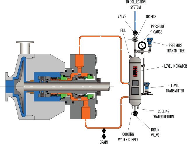
Plan 52 is a double seal. Leakage of the primary seal can be detected because product will be leaking into the seal pot. If the product tends to vaporize at flare pressure, the leak will be detected by pressure increasing behind the orifice in the vent line. If the product tends to remain liquid at flare pressure, the level in the pot can be seen to rise by the operators on normal rounds. If they fail to notice and the pot becomes full of liquid up to the orifice, then pressure will back up and be detected. A leak of the outer seal can be detected by visible leakage of the barrier fluid to the base. Also, the level of fluid in the pot could be seen to drop. However, in some services, depending on the barrier fluid used, the level could drop slightly just from barrier fluid vaporizing to flare. We see this with #1 fuel oil barrier fluid in not services. A loss of level in the pot is typically seen by operators on normal rounds checking the sight glass. A low level switch could also be used, especially for remote or unmanned installations to detect outer seal leakage.

In this plan external reservoir provides buffer fluid for the outer seal of an un-pressurized dual seal arrangement (Arrangement 2). During operation an internal pumping ring provides circulation. The reservoir is connected to a vapour recovery system and is maintained at a pressure less than the pressure in the seal chamber. It is normally used for the applications where process fluid leakage to atmosphere must be minimised and contained. Plan 52 works best with clean, non-polymerising pure products that have vapour pressure more than the buffer system pressure. Leakage of higher vapour pressure process liquid into buffer system will flash in the seal pot and escape into the vent system.


 8613371530291