
api plan 52 mechanical seal manufacturer
Depressurised buffer fluid circulation in outboard seal of a dual seal configuration through a seal support system. Circulation is maintained by using pumping ring in running condition and by thermosyphon effect in stand still condition.
1. Keep the sealant vessel vent continuously open, which is necessary to maintain buffer fluid pressure close to atmospheric pressure and vent the vapors to flare.
Circulation of buffer liquid to and from the reservoir is dependent on thermal siphoning and/or an internal circulating device (pumping ring) inside the seal.

The MP52 series aligns with API 682 Plans 52 and 53A. The Plan 52 is designed to support liquid buffer fluid for a containment seal chamber that is below the seal chamber pressure. The Plan 53A is a pressurized system designed to isolate the seal from the process completely by providing liquid barrier fluid at a pressure higher than the seal chamber.
Our seal reservoirs are built to ASME Section VIII standards and are available with ASME U code stamps. Flexaseal Engineered Seals and Systems, LLC provides standard and custom buffer fluid reservoirs that meet API 682 Standards. As an industrial seal pot manufacturer for the chemical, petrochemical, and industrial industries, our seal pot systems help protect the environment and your workers from hazardous materials.
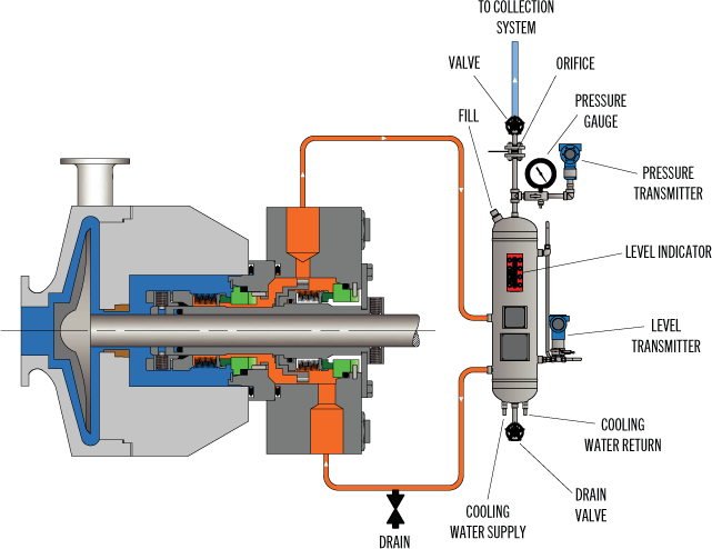
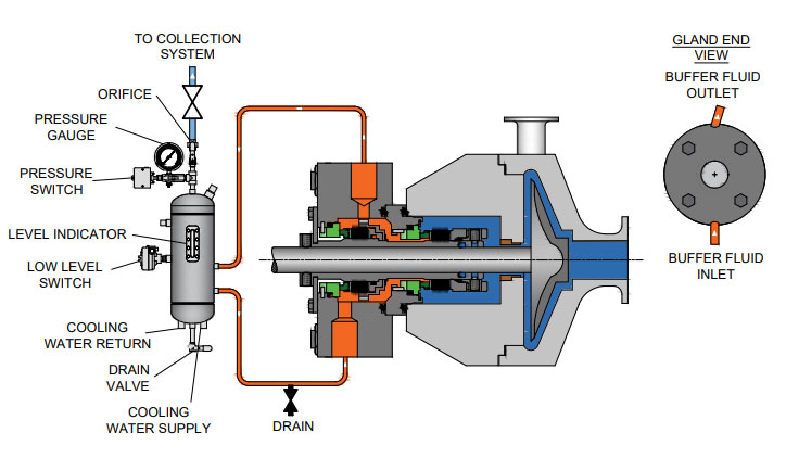
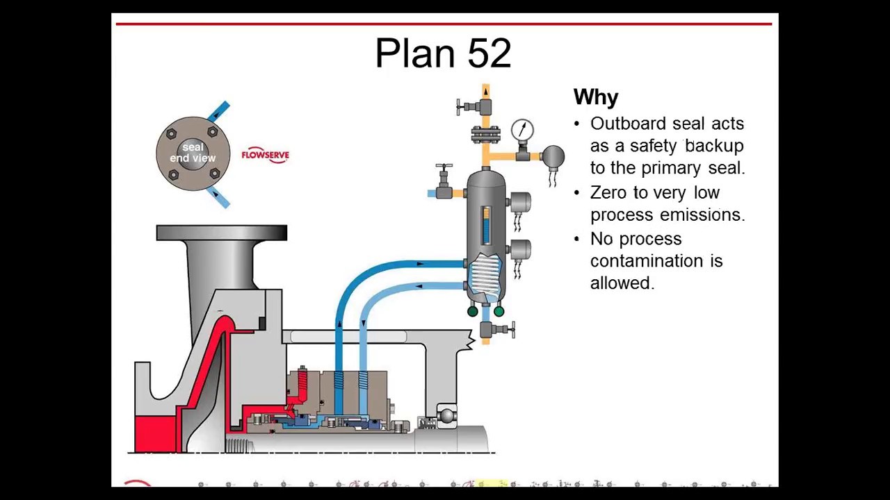
API Seal Plan 52 utilizes a reservoir and circulates an unpressurized buffer fluid between the inboard and outboard seals. To provide positive circulation through the support system and into the seal, a pumping ring is employed. Frictional losses in the buffer fluid inlet and outlet lines should be minimized by selecting the proper tube size, using large radius and/or 45 degree bends, and reducing the length of tubing runs. Seal Plan 52 is commonly used with light hydrocarbons or fluids with a high vapor pressure. The buffer fluid must be compatible with process fluid as inboard seal leakage will eventually mix with the buffer fluid.
Plan 52 is available as a seal pot assembly. The associated field installation kit for use in connecting the seal pot assembly to your system is also available. Assembly components may include:
See page 31 of the Mechanical Seal Support Systems Application Guide for additional details and ordering information. Contact your authorized Swagelok sales and service center for information on optional components.

These reservoir-based seal support systems are designed for both API Plan 52 and 53A applications to support unpressurized and pressurized dual seals. Circulation of buffer/barrier fluid is normally achieved with a pumping ring (or optional circulating pump), and a range of heat exchangers can be packaged with the system — selection dependent on available plant utilities.

Plan 52 uses an external reservoir to provide buffer fluid for the outer seal of an unpressurized dual seal arrangement. During normal operation, circulation between reservoir outer seal is maintained by an internal pumping ring. The reservoir is usually continuously vented to a vapor recovery system and is maintained at a pressure less than the pressure in the seal chamber. The process, or inner seal, of the dual unpressurized arrangement usually has its own piping plan. For example, the piping plans for a dual unpressurized seal arrangement might be written as Plan 11/52.
Reservoirs are usually made of pipe and piping components with an internal cooling coil. Unlike the heat exchangers used in Plan 23systems, cooling water flows through the coil; the buffer fluid flows over the exterior of the coil. It is important to realize that Plan 52 systems incorporate a vented reservoir.
Plan 52 systems are usually not controlled directly. The circulation rate depends on the performance of the pumping ring within the particular closed loop system. The pumping ring, reservoir and piping are selected to produce the desired operating conditions. Heat soak as well as heat generation must be considered in determining the desired circulation rate.
In the event that the process, or inner, seal fails, there will be a pressure and/or level increase in the reservoir, which produces an alarm. When this occurs, the reservoir is blocked in by closing the valve near the top of the reservoir. As the process seal continues to leak, pressure and fluid level in the reservoir increases further. The reservoir can potentially reach the same pressure as the process seal chamber. For all practical purposes, the outer seal takes over the full sealing duty. For these reasons, the recommended operating procedure is to begin planning an orderly shutdown and repair as soon as possible after failure of the process seal.
Plan 52 is used for both non-volatile and volatile process services. Although the leakage rate across the main, or process, seal is about the same as for a single seal, the leakage is directed into the reservoir of the dual unpressurized seal. In non-volatile services, the leakage from the process seal increases the liquid level in the reservoir. Depending upon the process fluid the reservoir may require periodic cleaning. In volatile services the leakage from the process seal vaporizes and is separated from the buffer fluid inside the reservoir. If the reservoir is connected to a vapor recovery system, the actual emission rate can be very low.

Flowway Teknik design and manufactures seals and associated products mainly for the oil and gas, chemical, pharmaceutical, pulp and paper, power, mining and many more industrial applications. Today, it provides the most complete selection of engineered mechanical seals and sealing support systems. Our products are recognized as a trusted brand in a process industry.
In this plan external reservoir provides buffer fluid for the outer seal of an un-pressurized dual seal arrangement (Arrangement 2). During operation an internal pumping ring provides circulation. The reservoir is connected to a vapour recovery system and is maintained at a pressure less than the pressure in the seal chamber. It is normally used for the applications where process fluid leakage to atmosphere must be minimised and contained. Plan 52 works best with clean, non-polymerising pure products that have vapour pressure more than the buffer system pressure. Leakage of higher vapour pressure process liquid into buffer system will flash in the seal pot and escape into the vent system.

You"re right, the friction of the seal faces will heat the buffer fluid, it can become quite hot. That being said, you still might not need to have cooling water or fins added to the reservoir or tubing.
Installation of the seal reservoir and tubing are of the utmost importance. Sight glasses, valves, narrow tubing, sharp bends in the tubing, and flowmeters should all be avoided. The tubing should be sloped at about 3 cm per meter back towards the seal, no high spots in the tubing, NONE. The fill line of the reservoir should be about a meter higher than the center line of the pump, and should be no further than about a meter from the seal. Your seal vendor should be able to provide literature with a nice diagram of an ideal installation.
The rotation of the seal will provide some windage to promote circulation of the buffer fluid, not much we"re talking a centemeter or so of head. Pumping rings provide a few cm of head and can be added to the seal, if not already installed. The temperature difference is what really drives the circulation of the buffer fluid. Your seal vendor might call this Thermosyphoning. The heat generated by the seal faces and the cooling effect of the tubing and the mass of the reservoir promote this. This is why minimal friction losses are important to the tubing installation. (generally pipefitters like to make thier work as neat as possible. do not allow them to tie the tubing to and from the seal together, keep the tubing lines apart so that they do not marginallize the temperature difference between them and reduce flow.)
Additionally, the way that the buffer fluid is added to the system can determine if the system will work. You must fill the reservoir and seal so that no air or vapor remains in the seal or tubing.
With an OEM pump package for an ANSI or DIN installation you"re likely to have a seal with connections on either side of the shaft. This works pretty well if you"re carefull about the way you add the buffer fluid. The connections are usually angled and called "tangential" ports. This is done again to reduce frictional losses in the system... it makes it easier for the buffer fluid to enter and leave the chamber in the seal. These connections do not make it easy to ensure that this chamber is liquid full. There may also be a connection at the top of the seal. Check the drawing provided with the seal to see if this port connects to the chamber between the two seals. If so, crack this port open when filling the seal letting the buffer fluid flow out of the seal along with the bubbles of air it"s displacing. When no more bubbles come out of the seal, it is full.
Some seals have connections at the top and bottom of the seal and do not angle the ports. This works well too, the seal "automatically" vents the air or vapor through the tubing. This can also be done with the standard ANSI or DIN seals by installing them 90 degrees off, as long as your bearing housing accomodates the tubing connections.
Be aware that the seal crack could have occured when a bubble of vapor finally budged allow flow to the seal... the cooler fluid suddenly hitting the hot seal faces could have caused thermal shock of a seal face.
In Part 3 of our series on Double/Dual Mechanical Seals we take a look at the best piping plans/support systems to put in place to increase seal/equipment reliability and reduce energy/water costs.
More importantly, to extend the life of a double/dual seal, you want to control the fluid film that comes into contact with the primary seal faces to establish the ideal lubrication, temperature and pressure within the seal. Across all types of mechanical seal failures, inadequate/incorrect seal support systemsare the second highest cause of seal failures (Figure 1).
Standard environmental control plans (also called piping plans) have been developed for double/dual seals and choosing the right environmental control plan is critical to your seal performance and reliability.
This plan is used when working with hazardous process fluids in which no leakage into the product can be tolerated. It provides a backup seal in case of inboard seal failure.
If an inner seal leak is not detected early enough, the higher pressure process fluid will displace the buffer fluid. This can result in the process fluid completely filling the barrier fluid chamber between the inboard and outboard primary seals. Should the outer seal leak, product will be released into the atmosphere.
This plan is used in services where no product leakage into the atmosphere can be tolerated. Plan 53’s biggest advantage over Plan 54DM, which does not use a tank, is its limited fluid volume. The amount of fluid that can enter the product system is limited to the volume of the barrier fluid tank itself (usually 2-3 gallons or 8-12 liters).
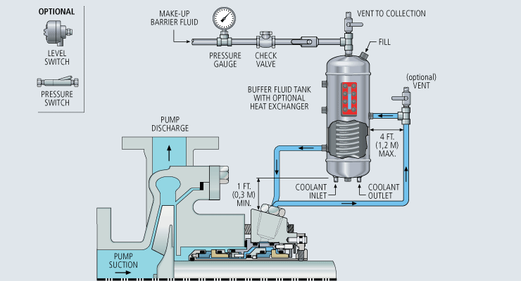
Uses a pressurized external reservoir or barrier fluid tank to provide a clean, pressurized barrier fluid to both the inboard and outboard primary seals of a pressurized double/dual seal.
The tank pressure must be maintained at the proper level. If the barrier fluid tank pressure drops, the system will begin to operate like a Plan 52, or unpressurized dual seal, which does not provide the same level of sealing integrity. Specifically, the inner seal leakage direction will be reversed and the barrier fluid will, over time, become contaminated with the process fluid.
Directs a clean compatible fluid into and out of the dual mechanical seal barrier/buffer fluid ports. The purpose of this fluid is to prevent the pumped fluid from damaging the inboard seal faces, to remove heat from the seal, and to lubricate the outboard seal faces.
Careful consideration should be given to the reliability of the barrier fluid source. When the source is interrupted or contaminated, the resulting seal failures can be very costly.
The higher the differential pressure, the more transfer/migration into the product. The control should never be used where the barrier fluid pressure is likely to fall below seal chamber pressure. If this were to happen, the failure of one inboard seal from any mechanical seal in the system could contaminate the entire barrier fluid system with product and cause additional seal failures.
Once the inboard seal wears out or fails, the amount of barrier fluid that entered the product system is virtually unlimited unless it is shut down quickly. Alerting instruments should be put in place to avoid this.
Using appropriate monitoring devices, alarms, switches, etc. will provide a means to monitor the health of your double/dual seal to identify potential issues in advance avoiding costly unplanned outages. A basic Plan 52 buffer system will have a sight glass to monitor the buffer fluid level, a pressure gauge and connections to and from the mechanical seal, as well as a vent and drain valve. Cooling coils and level switches are typically available as optional items.
A Plan 53 would have the same features as the Plan 52 with the addition of a pressure regulator, safety valve, and an optional pressure switch. These systems can be customized to meet customer specifications should they desire to have additional features incorporated into the system.
For assistance with using the best seal support system for your specific challenge, ask your local Chesterton office or contact our Ask the Expert service.


 8613371530291