
api plan 52 mechanical seal in stock
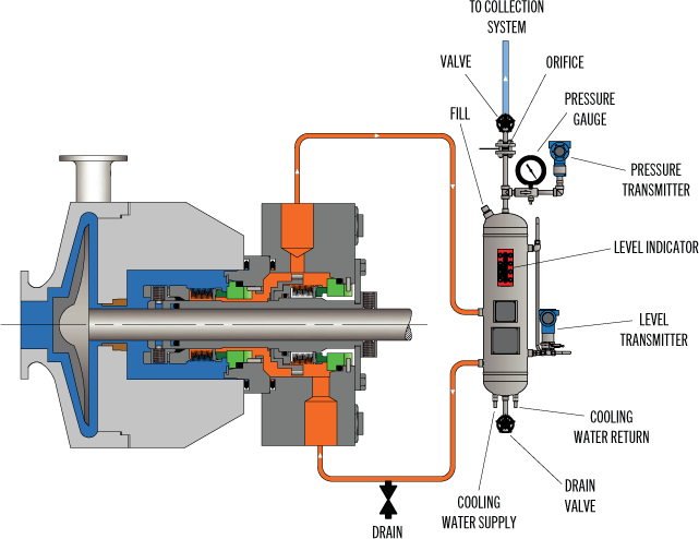
API Seal Plan 52 utilizes a reservoir and circulates an unpressurized buffer fluid between the inboard and outboard seals. To provide positive circulation through the support system and into the seal, a pumping ring is employed. Frictional losses in the buffer fluid inlet and outlet lines should be minimized by selecting the proper tube size, using large radius and/or 45 degree bends, and reducing the length of tubing runs. Seal Plan 52 is commonly used with light hydrocarbons or fluids with a high vapor pressure. The buffer fluid must be compatible with process fluid as inboard seal leakage will eventually mix with the buffer fluid.
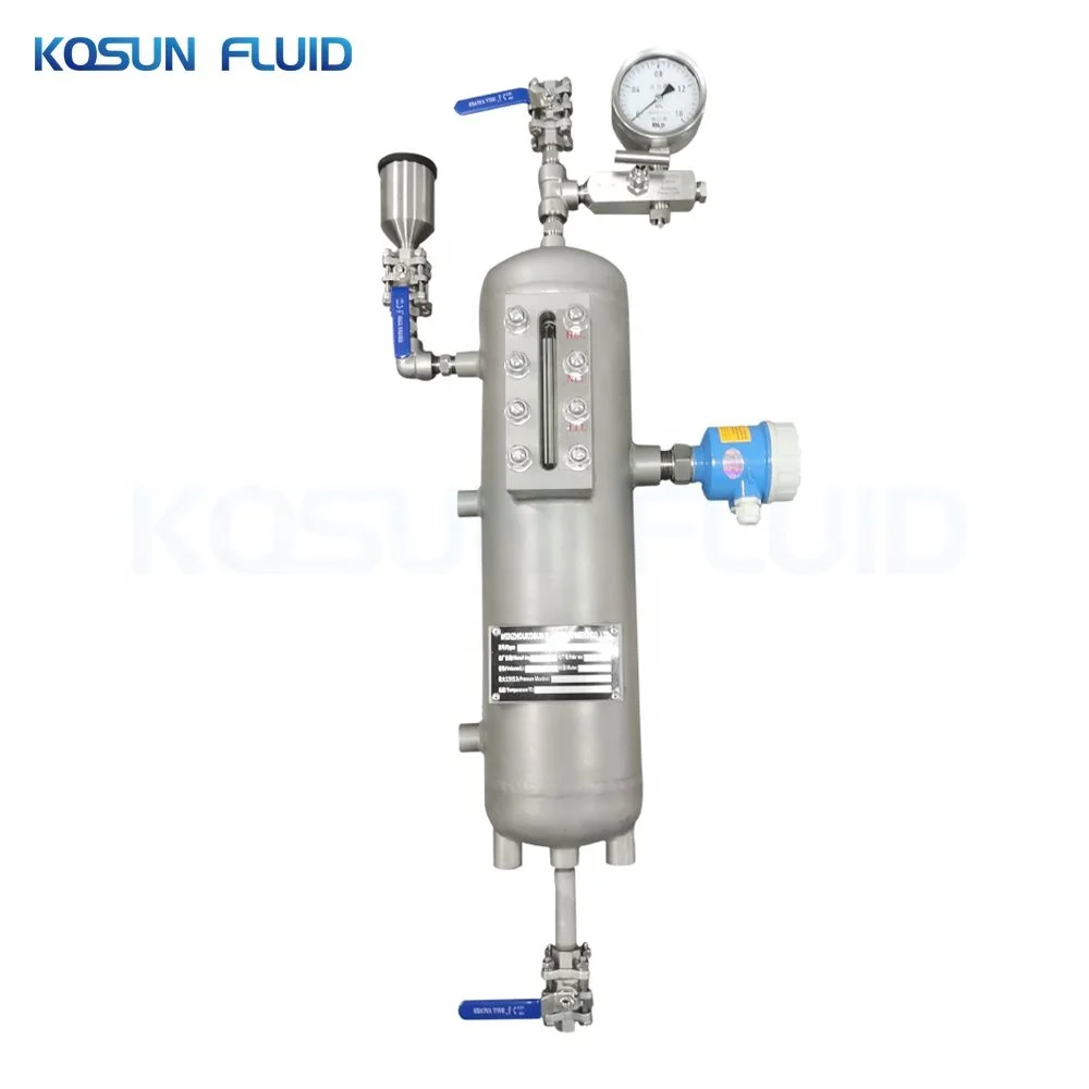
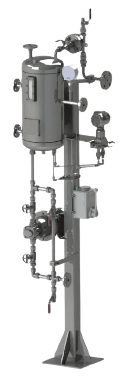
Plan 52 is available as a seal pot assembly. The associated field installation kit for use in connecting the seal pot assembly to your system is also available. Assembly components may include:
See page 31 of the Mechanical Seal Support Systems Application Guide for additional details and ordering information. Contact your authorized Swagelok sales and service center for information on optional components.
Depressurised buffer fluid circulation in outboard seal of a dual seal configuration through a seal support system. Circulation is maintained by using pumping ring in running condition and by thermosyphon effect in stand still condition.
1. Keep the sealant vessel vent continuously open, which is necessary to maintain buffer fluid pressure close to atmospheric pressure and vent the vapors to flare.

In Plan 52 there is an external reservoir providing buffer liquid for the outer seal of an Arrangement 2 seal. The buffer liquid shall be maintained at a pressure less than seal chamber pressure and less than 0.28 MPa (2.8 bar) (40 psi).
Plan 52 works best with clean, non-polymerizing, pure products that have a vapor pressure higher than the buffer system pressure. Use the STB TS-9/TS-12 for better operating conditions.

Circulation of buffer liquid to and from the reservoir is dependent on thermal siphoning and/or an internal circulating device (pumping ring) inside the seal.
In Part 3 of our series on Double/Dual Mechanical Seals we take a look at the best piping plans/support systems to put in place to increase seal/equipment reliability and reduce energy/water costs.
More importantly, to extend the life of a double/dual seal, you want to control the fluid film that comes into contact with the primary seal faces to establish the ideal lubrication, temperature and pressure within the seal. Across all types of mechanical seal failures, inadequate/incorrect seal support systemsare the second highest cause of seal failures (Figure 1).
Standard environmental control plans (also called piping plans) have been developed for double/dual seals and choosing the right environmental control plan is critical to your seal performance and reliability.
This plan is used when working with hazardous process fluids in which no leakage into the product can be tolerated. It provides a backup seal in case of inboard seal failure.
If an inner seal leak is not detected early enough, the higher pressure process fluid will displace the buffer fluid. This can result in the process fluid completely filling the barrier fluid chamber between the inboard and outboard primary seals. Should the outer seal leak, product will be released into the atmosphere.
This plan is used in services where no product leakage into the atmosphere can be tolerated. Plan 53’s biggest advantage over Plan 54DM, which does not use a tank, is its limited fluid volume. The amount of fluid that can enter the product system is limited to the volume of the barrier fluid tank itself (usually 2-3 gallons or 8-12 liters).
Uses a pressurized external reservoir or barrier fluid tank to provide a clean, pressurized barrier fluid to both the inboard and outboard primary seals of a pressurized double/dual seal.
The tank pressure must be maintained at the proper level. If the barrier fluid tank pressure drops, the system will begin to operate like a Plan 52, or unpressurized dual seal, which does not provide the same level of sealing integrity. Specifically, the inner seal leakage direction will be reversed and the barrier fluid will, over time, become contaminated with the process fluid.
Directs a clean compatible fluid into and out of the dual mechanical seal barrier/buffer fluid ports. The purpose of this fluid is to prevent the pumped fluid from damaging the inboard seal faces, to remove heat from the seal, and to lubricate the outboard seal faces.
Careful consideration should be given to the reliability of the barrier fluid source. When the source is interrupted or contaminated, the resulting seal failures can be very costly.
The higher the differential pressure, the more transfer/migration into the product. The control should never be used where the barrier fluid pressure is likely to fall below seal chamber pressure. If this were to happen, the failure of one inboard seal from any mechanical seal in the system could contaminate the entire barrier fluid system with product and cause additional seal failures.
Once the inboard seal wears out or fails, the amount of barrier fluid that entered the product system is virtually unlimited unless it is shut down quickly. Alerting instruments should be put in place to avoid this.
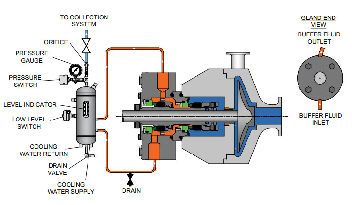
Using appropriate monitoring devices, alarms, switches, etc. will provide a means to monitor the health of your double/dual seal to identify potential issues in advance avoiding costly unplanned outages. A basic Plan 52 buffer system will have a sight glass to monitor the buffer fluid level, a pressure gauge and connections to and from the mechanical seal, as well as a vent and drain valve. Cooling coils and level switches are typically available as optional items.
A Plan 53 would have the same features as the Plan 52 with the addition of a pressure regulator, safety valve, and an optional pressure switch. These systems can be customized to meet customer specifications should they desire to have additional features incorporated into the system.
For assistance with using the best seal support system for your specific challenge, ask your local Chesterton office or contact our Ask the Expert service.

In this plan external reservoir provides buffer fluid for the outer seal of an un-pressurized dual seal arrangement (Arrangement 2). During operation an internal pumping ring provides circulation. The reservoir is connected to a vapour recovery system and is maintained at a pressure less than the pressure in the seal chamber. It is normally used for the applications where process fluid leakage to atmosphere must be minimised and contained. Plan 52 works best with clean, non-polymerising pure products that have vapour pressure more than the buffer system pressure. Leakage of higher vapour pressure process liquid into buffer system will flash in the seal pot and escape into the vent system.
Cyclone separators are typically used in an API Plan 31 arrangement and incorporated in the seal flush line (API Plan 11 ) from the discharge of the pump.
53B accumulator-based seal support systems utilize a bladder to maintain system pressure to pressurized dual seals and absorb barrier fluid thermal expansion while separating the pressurizing gas and barrier fluid.
53C accumulator-based seal support systems utilize a piston to maintain system pressure to pressurized dual seals and absorb barrier fluid thermal expansion while separating the pressurizing gas and barrier fluid.
Used to detect and monitor leakage of the inboard seal, these seal support systems can detect liquid leakage (API Plans 65 and 75) or gas leakage (API Plan 76), or a mixture of gas and liquid leakage (API Plan 75).
Used to detect and monitor leakage of the inboard seal, these seal support systems can detect liquid leakage (API Plans 65 and 75) or gas leakage (API Plan 76), or a mixture of gas and liquid leakage (API Plan 75).
Used to detect and monitor leakage of the inboard seal, these seal support systems can detect liquid leakage (API Plans 65 and 75) or gas leakage (API Plan 76), or a mixture of gas and liquid leakage (API Plan 75).
A PG 72 (API Plan 72) system is used to provide a clean, regulated gas supply to a dual unpressurized seal arrangement where the containment seal is dry running.
A PG 74 (API Plan 74) system provides a clean, dry, regulated supply of pressurized barrier gas (usually nitrogen) to dual pressurized, non-contacting seals.
These reservoir-based seal support systems are designed for both API Plan 52 and 53A applications to support unpressurized and pressurized dual seals.
Plant seal water filtration system, maintaining clean water supply to improve the reliability mechanical seals and gland packing and also flow control and pressure-regulating devices.
SafeJet is an automatic seal water filter. Its operation is based on “flow-through” filter technology, which utilizes reliable laminar filtering method.
Water-cooled heat exchangers may be applied where water is readily available. Heat exchangers may be packaged together with seal support systems when additional cooling is required.
Water-cooled heat exchangers may be applied where water is readily available. Heat exchangers may be packaged together with seal support systems when additional cooling is required.
Most centrifugal compressors today use dry gas seals to contain high-pressure gas, whether on a high-pressure reinjection duty or a low-pressure pipeline machine.
In the past there was only one Plan 53, but with the 2nd Edition of API 682 and the 1st Edition of ISO 21049 other variations of Plan 53"s were created.
Plan 53A is the former Plan 53. Plan 53B is what had been in the past denoted as Plan 53 Modified; this is especially popular in European and other countries in the Middle East. Plan 53C is a variation of this that has also been used in the past and is now formally recognized.
The major difference in the plans is that Plan 53A uses an external reservoir, while Plans 53B and 53C run within a closed loop system with a make-up system piped to it for replenishment of the barrier fluid.
In dual pressurized sealing arrangements the inner process seal can have its own flush plan; in such applications the complete flush plan system designation should include both plans. For example, Plan 11/53A means that the inner seal has its own flush plan, Plan 11. The API/ISO default is for no separate flush plan when using any of the Plan 53"s, but this can vary with the application conditions.
With the older traditional back-to-back seal arrangement the inboard seal usually does not require a separate flush. In applications such a hydrofluoric acid, where it is both extremely hazardous and corrosive, a Plan 32 can be used in conjunction with a Plan 53. The dual pressurized face-to-back seal arrangement eliminates some of the potential problems associated with the back-to-back design. This face-to-back seal arrangement sometimes incorporates a reverse pressure capability that is not a default with the back-to-back design.
Also, face-to-back arrangements do not have a dead zone underneath the inboard seal that can become clogged by dirty process fluid and lead to seal hang-up. However, the face-to-back arrangement is not a cure-all. With the product on the seal O.D. and with it being used on API pumps that still incorporate throat bushings, it is advantageous to provide a flush for the inboard seal on a number of applications.
Abrasives can accumulate in the more closed API type seal chambers compared to the newer generation chemical duty pumps with large cylindrical bore or tapered bore chambers. The use of a Plan 11 or similar bypass type flush for the inner seal has advantages. It can help keep the seal chamber clean. It also has an improved overall heat transfer setup versus just using a Plan 53 system alone.
In comparison to a Plan 54, Plans 53A/B/C are usually less complex and less expensive. With Plans 53A/B/C, both the inner and the outer seals are lubricated by the barrier fluid, which can be selected for optimum seal performance. Plans 53A/B/C are usually selected for dirty, abrasive, or polymerizing process services which might be difficult to seal directly with single seals or with dual unpressurized seals using a Plan 52. There will always be some leakage of the barrier fluid into the process with any pressurized system.
With some of the Plan 53 systems the volume of barrier fluid is limited, especially compared to a Plan 54 system. Venting of the seal chamber is essential for all Plan 53"s where vapor locking can if vapor bubbles collect near the pumping ring or in the piping.
Plan 53A uses an external reservoir to provide barrier fluid for a pressurized dual seal arrangement. Reservoir pressure is produced by a gas, usually nitrogen, at a pressure greater than the maximum process pressure being sealed. The gas pressure is regulated by a system that is outside the schematic of the piping plan. Circulation of the barrier fluid is maintained by an internal pumping ring.
Like Plan 52 reservoirs, cooling is accomplished internal coil of tubing to remove the heat. Also like Plan 52 reservoirs, the volume of barrier liquid can vary from two gallons to 5+ gallons, where API and ISO standards specify 3-gal and 5-gal, depending upon the shaft diameter.
For non-API specifications, smaller reservoirs - typically 2-gal - are often used, especially at ambient pumping temperatures. Pressure alarms, pressure gages and level switches are typically standard equipment and are required by API 682/ISO 21049.
The usual guideline for Plan 53 barrier pressures is that they be a minimum of 20-psi to 50-psi above the maximum process pressure seen by the seal. Barrier pressure is normally supplied by a plant wide distribution system. Nitrogen bottles should not be used as they require a lot of attention and maintenance.
API 682/ISO 21049 recommends that the system be limited to 150-psig due to gas entrainment into the barrier fluid. Field experience has shown that with the proper barrier fluid, Plan 53A systems can be used up to 300-psig if the temperature is controlled to less than 250-deg F. A variation to this would be to use an accumulator to eliminate gas entrainment.
Disadvantages (vs. other Plan 53 systems)The barrier fluid in Plan 53A is subject to gas entrainment due to direct exposure to the pressurizing gas. Different barrier fluids have varying levels of gas entrainment.
Installation should be limited to a single seal installation even on between bearing pumps. Therefore for a large number of installations, Plan 53A can be more expensive than Plan 53B or 53C.
nlike a Plan 53A that incorporates a pressurized reservoir within the circulation loop, Plan 53B incorporates a bladder type accumulator along with the piping and an air or water cooled heat exchanger to provide for barrier fluid capacity.
Some installations use finned tubing as the heat exchanger, but these should be used with caution as the heat removal depends upon a positive air flow across the tubing to be effective. Gas entrainment is not a problem with this plan since it incorporates bladder accumulator to maintain the barrier pressure within the closed loop circuit.
The accumulator should be pre-pressurized to between 80 percent and 90 percent of the barrier pressure. This creates a problem in that it limits the volume of fluid within the Plan 53B circuit. The majority of the accumulator volume is gas. The basic setup is comprised of two parts; the closed loop circulating system made up of the piping and heat exchanger and the make up system.
Flow in the circulating system is usually induced by an internal pumping device. The make up system can be configured a number of ways based upon the customer"s preference, ranging from a simple hand pump to an elaborate pumping system feeding multiple pumps/seals.
Like Plan 53A, the flow rate of the Plan 53B circuit is controlled by the pumping ring design, peripheral speed, barrier fluid viscosity, and resistance of the piping circuit; the piping circuit of 53B includes a heat exchanger. The sizing of the heat exchanger depends upon the heat load of the system. The heat exchanger should be designed to contribute minimum resistance.
API 682, 3rd edition does not provide guidelines for sizing the accumulator of Plan 53B, but the total fluid volume of the system should be about the same as the volume of a 53A system.
Disadvantages (vs. other Plan 53 systems)The volume of fluid within the closed loop circuit is very limited, as little as one-half gallon in some instances.
With the limited fluid volume the barrier fluid gets thermally cycled on a much more frequent basis than a Plan 53A, so the service life of the fluid is reduced.
The finite volume of the accumulator requires a designed pressure operating range between refills (in excess of that required for a Plan 53A) and this must be built into the pressure rating of the seals.
The separate heat exchanger introduces additional flow resistance to the piping system and will have a lower flow rate than an otherwise identical Plan 53A.
Plan 53C is a variation of Plan 53B that uses a piston accumulator to track the pressure of the seal chamber. In Plan 53C, the piston accumulator has a reference line from the seal chamber to the bottom of the accumulator. There are differences in diameter of the internal piston so that a higher pressure is generated on the top half, which in turn is piped to the circuit loop into and out of the seal chamber.
Similar to Plan 53B, there is no gas pressurizing the barrier fluid so there is no chance of gas entrainment. Also, like Plan 53B flow is generated by a pumping ring through a heat exchanger. The heat exchanger can be water cooled, air cooled or can be finned tubing if the heat load is small enough. This system should be used with caution, as the reference line to the accumulator is subject to the process fluid. The process fluid may be corrosive, abrasive, or a slurry that could potentially clog the pressure reference line threatening the tracking ability of the system.
The advantages and disadvantages are the same as the Plan 53B system. Additionally, the disadvantage of this system is that pressure spikes or pressure drops in the process pressure will vary the pressure on the outer seal that may create a temporary leakage condition. Also, tracking pressures can always be subject to delays that can cause a temporary loss of positive pressure differential across the inboard seal.
PHOTO : https://www.eagleburgmann.com/media/literature-competences-products-solutions/division-mechanical-seals/competences/brochure-barrier-buffer-media-for-mechanical-seals

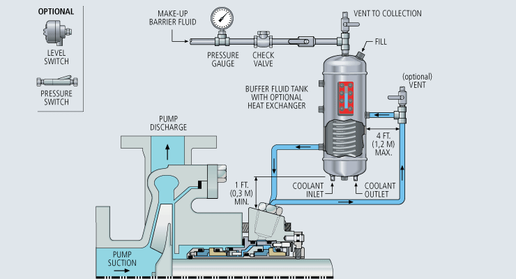
Plan 52 uses an external reservoir for providing buffer fluid for the outer seal of an unpressurised dual seal arrangement. Cooling coils in the reservoir are available for removing heat from the buffer fluid.
For Plan 53A, reservoir pressure is produced by a gas, usually nitrogen. A pumping ring maintains circulation during operation. Thermosiphon action is in effect during standstill. Reservoir size can be optimised in accordance with the flow rate. Any particles tend to settle at the bottom of the reservoir and don"t get recirculated. Similar to Plan 52, cooling coils are also used. Proper safeguards against the backflow of barrier fluid into the external supply of nitrogen also need to be considered.
Plan 53B makes use of an accumulator for isolating the pressurizing gas from the buffer fluid. A heat exchanger is also included in the loop in order to cool the fluid. It can either be water cooled, finned tubed, or air-cooled, depending on the system heat load.
Plan 54 employs an external source for providing a clean pressurised fluid. Plan 54 systems can be custom-made so as suit various application requirements and provide pressurised flow to various seal installations, thus keeping costs down.


 8613371530291