
api plan 61 mechanical seal pricelist
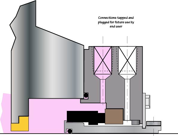
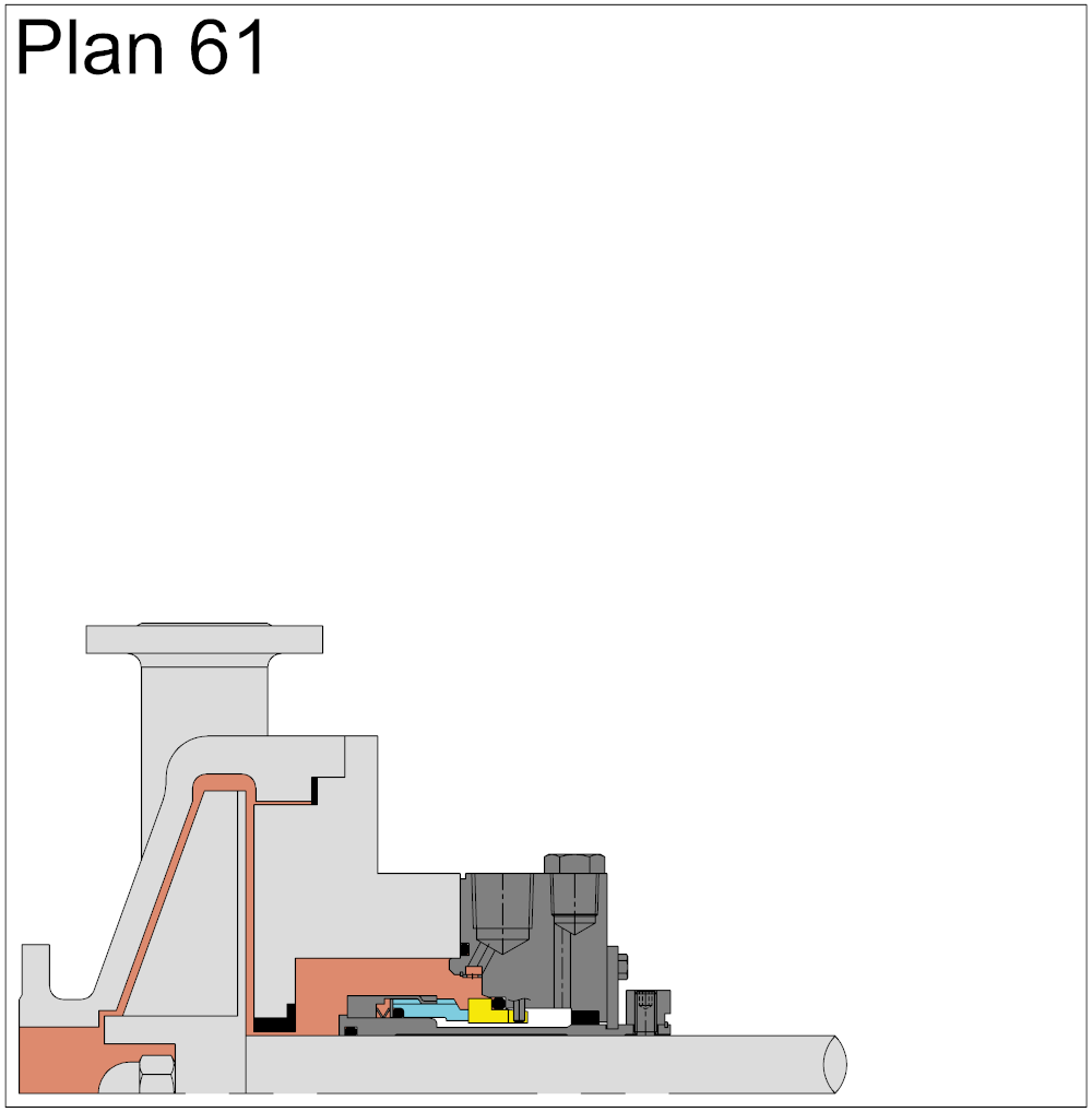
In Plan 61, only connections are supplied. Plan 61is sometimes used if the end user has a special or as yet undefined future use for the connections. Flush, Quench and Drain connections are supplied and plugged with plastic plugs.
FSI Series 1015 mechanical cartridge seals are a premium grade product without the premium price. They"re ideal for use with most ANSI and DIN (standard and big bore) pumps and other types of pumps and rotating equipment. They have the following features:
5. GENERALLY, API STANDARDS ARE REVIEWED AND REVISED, REAFFIRMED, OR WITHDRAWNAT LEAST EVERYFIVE YEARS. SOMETIMES A ONETIME EXTENSION OF UPTO TWO YEARS WILL BE ADDED TO THIS REVIEW
API standards are published as an aid to procurement of standardized equipment and materials. These standardsare not intendedto inhibit purchasersor producers from purchasing
1A.22 maximum static sealing pressure: The highest pressure, excluding pressures encounteredduring hydrostatic testing, to which the seals can be subjected while the
1.4.51 throttle bushing: A device that forms a restrictive close clearance around the sleeve (or shaft) at the outboard end of a mechanical seal gland (see Figure D- 1,
cartridge design. For this standard, a cartridge design consists of a mechanicalseal unit, including sleeve, gland, primary seals, secondary seals, etc., that can be testedas a unit
seals; however, the design and of the mechanical seal from dislodging as a result of chammaterials of the component parts shall be suitable for the spec-ber pressure.
piping and appurtenances specified by the purchaser. Mechanical seal piping shall be in accordance with the appropriate plan of Appendix D, and the plan shall be indicated
seal chamberface shall incorporatea confined gasket to prevent blowout.The gasket shallbe of thecontrolled compression type (for example,an O-ring or a spiral wound gasket)
connection in either the seal chamber or seal flush piping. Systems needing manual venting re- speed range.The analysis shall be performedas described in
l . These plans represent commonly used systems. Other variations andsystems are available and should be specified in detail by the purchaser and mutually agreed upon by the
4. When supplemental seal fluid is provided, the purchaser will specify fluid characteristics. The vendor shall specify the volume, pressure, and temperature required, where
Database” in the 7th Editionof A P I Standard 610.The data exchange file outlined in this specification extends beyond thescope of the API Standard 610 data sheets (Appendix B), such that data
7th Edition pump bearing bracket webs. These criteria allow h. Clear length, E, is a new minimum dimension. APIStandard 610 requires that pumps have a separable gland. The
c. These dimensions are slightly larger than in the 7th Edi610. However, the radial dimension has i. Stud sizes have been chosen basis ASME calculations to
A secondary use of the used oil is to burn it for energy. Large industrial boilers can efficiently burn the used oil with minimum pollution. As a result some used oil is sent to power plants or cement kilns to be burned as fuel. On a smaller scale small quantities of used oil are burned in specially designed heaters to provide space heating for small businesses.
Motor oil has value even after it has been drained from an engine. The oil you take to a collection center to be recycled saves energy. It can be reprocessed and used in furnaces for heat or in power plants to generate electricity for homes, schools, and businesses. It can also be sent to a refinery that specializes in processing used oil and re-refined into lubricating base oils that can be used to formulate engine oils meeting API specifications.
This application is a division of prior application Ser. No. 09/687,393, filed Oct. 13, 2000 now U.S. Pat. No. 6,662,062, which is a continuation of prior application Ser. No. 09/179,506, filed Oct. 27, 1998 now U.S. Pat. No. 6,173,210, which is a continuation of prior application Ser. No. 09/033,194, filed Mar. 2, 1998, now abandoned each such application entitled APPARATUS AND METHOD FOR SELECTING A MECHANICAL SEAL and each such application hereby incorporated herein by reference.
This invention relates to automated systems for supporting selection of a mechanical seals for equipment. More particularly, the invention relates to automated systems for supporting advertising, selecting, designing, manufacturing and providing post sales service and support for mechanical seals.
Sales and marketing of mechanical seals presently involves several activities including seal selection, design and engineering of a seal, manufacturing, and post sales service and support. This process involves many different people to gather, manipulate, interpret and process a variety of kinds of information, and is not an exact science.
A mechanical seal is a shaft sealing device provided to contain process fluids within equipment such as a pump, mixer or other rotary equipment. Mechanical seals are used in operations of a typical processing plant. Significant industries that use seals include: pulp and paper, chemical processing, petroleum chemical, oil refining, food processing, and power and utilities, among others.
There are generally three types of mechanical seals: component (made of several pieces), cartridge (components unitized for one piece) and split seals. Cartridge seals generally are preferred over component seals for several reasons. First, cartridge seals may be installed without significant training. These seals also may be tested before shipping to ensure sealability. However, conversion from a component seal to a cartridge seal for an application involves a complex process of selection of an appropriate seal design.
Because of the variety of applications for seals, selection of a seal involves considering several factors. For example, seals typically are connected to equipment with a rotary shaft (pumps being the most common) for which there are a large variety of commercially available designs with different dimensional profiles. Equipment also may have been modified in the field for several reasons, resulting in a nonstandard dimensional profile. Additional factors are the operating conditions of the equipment, including process fluids and their combinations, and intentional and unintentional changes in the process fluids used in a systems. Aside from selecting a seal that fits the equipment and is suitable for the given operating conditions, costs of the seal and its installation also are factors.
This selection process therefore generally involves highly trained sales engineers with factory support to perform properly the seal selection process. Their training typically includes mechanical and design engineering and chemical engineering. These individuals typically also perform sales, service and support functions. Because of the complexity of the seal selection process, customers tend to be dependent on these sales engineers. This dependency is due to the complexity of part codes for these seals.
The expertise level of a sales engineer is generally dependent on the size of seal manufacturer, years of experience, education and training, resulting in varying competencies. Sales engineers may possess only industry specific expertise, acquired from their experience. Accordingly, without extensive experience, a sales engineer also may be dependent heavily on factory support for assistance in the seal selection process.
Moreover, sales engineers, despite their experience, still may be dependent on factory support because they typically have immediate access to selection information limited to common equipment and process fluids, either in printed or computer-readable text form. Other information, such as application data, engineering data, special pricing and drawings may be available only at the factory, requiring the sales engineer to use factory support to derive seal selections or to interpret the available information and to select a seal. Accurate communication between sales engineers and factory engineers is a critical component of this process.
Depending on the resources available to a manufacturer, which may depend on its size or its number of years in business, factory support may be limited to manually intensive selection methods prone to errors resulting in an informal, unscientific selection process. Even with more sophisticated procedures based on significant amounts of historical information, however, human intervention is generally required for many decisions made between field sales and factory support personnel because of individuals" judgments and perceptions, which may result in inaccurate selections. In particular, a significant amount of human interaction is required to gather, interpret, manipulate and analyze the application data when the sales engineer requires factory support. In particular, the pump and seal dimensions, operating conditions and process fluids affect the selection of materials to obtain maximum seal life. The human interaction involved in current selection methods may result in different recommendations from different individuals, for the same application, of a seal model, optional seal features, materials of construction, seal environmental controls, i.e., piping plans, and various auxiliary devices to be used with the environmental controls. In addition, the likelihood of an error is increased. An error in any stage of the selection process may result in an inaccurate or incomplete sealing solution, which translates into premature seal failure and increased costs.
There are several steps in the seal selection process which typically involve human interaction. One step is identification of the equipment, e.g., a pump or drive motor or other rotary equipment. The methods of identification differ among sales engineers. Example sources of identification information include identification tags on the equipment, maintenance records, engineering records, purchasing records, equipment manufacturer"s records or seal manufacturer"s records. If these sources provide incomplete information proper equipment identification may be impossible. Even if equipment is properly identified, e.g., by make and model, modifications may have been made to the equipment. A failure to identify such modifications results in an erroneous seal selection. As a result, a trained individual measures the equipment to obtain accurate dimensional data. Dimensional data is commonly collected using forms of varying complexity and completeness. Simple forms tend to be incomplete. Complex forms tend to be subject to interpretation by sales engineers and factory engineers. Both kinds of forms result in errors.
A seal model which is dimensionally compatible for the identified equipment then is selected. In order to make this selection, a sales engineer may refer to information available in a reference guide, or if not identified in a reference guide, performs a dimensional analysis. The dimensional analysis may be performed by the sales engineer or by relying upon factory support. When application data is received at the factory, it is reviewed for completeness and accuracy. If the data is not satisfactory, the process is delayed.
After a dimensionally compatible seal model has been selected, the operating conditions are identified by the sales engineer and are analyzed to confirm that the recommended seal is suitable for the process performed by the equipment. This analysis involves evaluating the operating conditions and the process fluids, with respect to a number of aspects of the seal, including, but not limited to: a metallurgy for general corrosion resistance; a face material combination for lubricity of the chemical and/or corrosion or abrasion resistance; and selection of secondary sealing components, i.e., o-ring elastomers for temperature and chemical resistance.
The operation conditions include but are not limited to: shaft speed as related to seal chamber pressure acting on the seal, i.e., pressure/velocity; stuffing box/seal chamber pressure, which is a function of different pump internal part designs (impellers); shaft speed; pump discharge pressure at outlet nozzle; pump suction pressure at inlet nozzle; pressure/velocity parameters for different seal designs and face material combinations; box pressure calculations based on pump design type; seal face balance design; concentration; temperature; viscosity; the percentage of undissolved or dissolved or fibrous or nonfibrous solids; vapor pressure; specific gravity; and pollutants and other chemicals. Sometimes these values are estimated or are not obtained.
Either the sales engineer or factory support may analyze the operating conditions, depending on experience and resources. The parameter limits for various operating conditions generally are maintained in printed engineering tables by seal type, or may be calculated. If this analysis is performed by untrained individuals using only printed tables and without an engineering level analysis, or if incomplete information is used, then the analysis may be inaccurate or erroneous. It may also be inappropriate to select the material of a previous seal.
If the analysis indicates that a standard seal model is not acceptable, appropriate modifications to either a seal or the equipment are determined. An engineer may have a limited information guide explaining the modifications to be made to popular pumps to fit popular seals. Modifications to a seal generally are not provided. Otherwise the modifications are determined, either by the sales engineer or factory support, by reference to various guides or by analysis or based on historical information such as previous bills of material and factory engineering drawings. If the information used to make the modifications is inaccurate or incomplete, an inappropriate modification may be made to the seal or the equipment.
The process fluids also are analyzed to review characteristics which may affect seal selection, such as, but not limited to: volatile hazardous air pollutants, which requires selection of a double seal for absolute zero vapor emission leakage; flammability; toxicity; polymerization; solidification; abrasive slurries; percentage concentration of primary and secondary chemicals; and minimum and maximum process temperatures.
If a sales engineer has a reference guide with material ratings for a seal, the final seal selection is made by the sales engineer based on training and experience. A reference guide also may indicate materials for use with only one process chemical, without consideration of secondary chemicals which may be present in the process. If the guide is not complete, factory support may be required for assistance. An engineer providing factory support analyzes the process to identify the process fluid chemical characteristics, for example by utilizing published technical reference sources, chemical dictionaries, or historical information such as previous bills of material, or by basing a selection on properties of a chemical with similar characteristics. As with other steps involving factory support, information may be missing from the sales engineer, thus incurring a delay or resulting in an incorrect selection. Because of the complexity of the process fluid analysis, errors in selection are possible.
The sales engineer also selects optional seal features to obtain optimum seal performance life. Such features include, but are not limited to: a two piece stationary face (for viscous or polymerizing chemicals); a quench and drain gland (to cool or heat seal faces, or wash away crystalline deposits on atmospheric side of the seal faces); and pumping sleeves for double seals to provide maximum flow of barrier fluid to cool and lubricate the seal faces. The limited information on optional features in a reference guide may be limited. Otherwise, sales engineers derive the selection of optional features from the chemical characteristics. Whether a given seal has optional features to handle the application may require factory support for a recommendation.
Another step of the seal selection process is determining the best environmental controls or American Petroleum Institute (API) standard plan. The environmental controls are systems used to cool, lubricate, heat, etc., thereby controlling the environment of the mechanical seal, particularly at the seal faces. For an existing application, the sales engineer identifies the current external piping system and evaluates whether it should be modified for the application. For a new application, the sales engineer identifies piping systems available. A limited reference guide may help derive selection of the piping plan or factory support may be required. This aspect of the selection process may even be neglected or an existing piping plan may be incorrect for the application, thereby resulting in premature seal failure. Significant interaction between customers, sales engineers, and factory engineers may be required for proper selection.
Another step of the seal selection process is the selection of a variety of auxiliary devices, i.e., products external to the seal and typically in the piping plan, including but not limited to: supply tanks for double seal piping systems; throat bushings for use with external clean flush systems to seal faces; and flow control devices for external flush systems for single seals and double seals. As with other aspects of this process, such devices may be selected using limited reference guides, or application engineers may calculate the design, size and selection of an auxiliary device. Depending on the type of auxiliary, e.g., throat bushings, equipment dimensions may be needed by an engineer to design and manufacture the device.
After a seal with appropriate materials and optional features, environmental controls and auxiliaries have been selected, an appropriate price is determined along with a bill of materials and specifications for installation. Current pricing methods for mechanical seals for standard products typically involves price lists or books. The pricing book may be complex and may require factory support to be interpreted in order to arrive at a price for a given seal selection. When special designs are made, a selling price and discount structure is more complex to determine, and typically involves trained engineers and accountants. The entire quotation process involves time frames ranging from days to weeks.
Ultimately, after quotation and receipt of an order, a seal is manufactured according to the quotation if the seal is not a standard part. Manufacturing operations vary based on the size and scope of products offered by a seal manufacturer and the manufacturing process technologies used. The kinds of manufacturing equipment used ranges from manual equipment to computer numerically controlled (CNC) equipment in various combinations depending on the scope of products and raw materials for the products. Despite the size of the manufacturer, highly trained individuals typically are needed for manufacturing.
While some manufacturers may use a computer program to assist in seal selection, such computer programs are generally an automated look-up table with which a user selects a model number of a pump, a corresponding product line of seals and receives a selection of possible seals. In some cases, the user may even select the materials for the seals. Such tools generally require either mechanical or chemical engineering knowledge or a significant amount of experience in order to select a seal correctly.
In sum, because of the complexity of the seal selection process, manufacturing and marketing of mechanical seals requires seal manufacturers to be dependent upon highly trained individuals. Customers depend on sales engineers and the manufacturer for technical support in order to obtain accurate solutions to field service problems. Because of complexity, delay and cost of the seal selection process, a customer may replace a failed seal with a seal of the same type rather than make a corrective selection. Premature seal failure may continue to occur, resulting in excessive operating costs.
The combination of the complexities and requirements of seal selection, quotation, design and engineering, manufacturing and post sales support processes thus produces inconsistent, unscientific and erroneous results, and increased costs.
The various difficulties with existing seal selection methods are overcome by providing a standardized process for gathering, analyzing, interpreting and deriving data relating to the seal selection process. In particular, equipment dimensional profiles for standard equipment are stored in a database. This database may be searched using several kinds of identification information of the equipment. Help information is provided to indicate to the user how to make proper measurements on the equipment. In addition, dimension verification information is provided to assist the user in verifying that the equipment has not been modified.
Given proper equipment identification, a compatibility analysis is performed between the equipment and seals in a seal database to determine which seals are dimensionally compatible with the identified equipment. This compatibility information may be stored with the equipment information in the equipment database.
A process fluids database specifies recommended materials for various process fluids. A user is prompted to specify process fluids. This system automatically determines which materials are recommended for the specified process fluids and selects a seal that is available in the selected materials.
A seal specifier uses the information input by the user, the process fluids database, the seal styles database, and the equipment profile database to determine an appropriate seal for the specified equipment. The seal specifier allows a user to select seal based on a known product number for the seal, or by specifying information about either equipment or the seal, and accommodates the addition of a new equipment to the equipment database. The equipment may be identified by specifying the frame or group of the equipment, a part number, or by its dimensions. These varieties of methods allow a non-specialist to select a seal by providing information simply about the equipment and the process in which the equipment is used.
In the process of specifying a seal, the compatibility analysis performed between the seal and the equipment may indicate that a modification should be made either to a standard seal or to the equipment to fit the standard seal. The specified seal and any modifications may be provided to a manufacturing center. By including a database with a variety of drawings and template programs for a computer numerically controlled machinery, the dimensions of a modified seal may be inserted into a template program to automatically generate a custom seal design to manufacture a custom seal.
By having a seal styles database with established limits for materials and operating conditions, the system automatically compares the input process fluids and operating conditions to the database to select a best seal model from among those seals which are dimensionally compatible with the equipment. A compatibility rating for process fluids assists in the prioritization of the seal models available in the recommended materials for the specified process. By allowing a user to specify secondary chemicals in the process stream, the quality of the seal selection is improved. The material and compatibility ratings and operating condition limits for a seal model may be compiled from material suppliers and other engineering guides into the process fluids database and the seals styles database. Similarly, environmental control typing plans and auxiliary devices may be associated with each seal model in the seal style database, automating the selection of such products.
Accordingly, in one aspect an apparatus for determining a seal for a piece of equipment includes a database of equipment profiles and a database of seal profiles. A seal selection module is coupled to the database of equipment profiles and the database of seal profiles, the seal selection module having an input that receives data indicative of a characteristic of the piece of equipment from a user, and an output that accesses the database of equipment profiles to determine a seal from the database of seal profiles that meets the desired characteristic and fits the piece of equipment. Another aspect is the process performed by such an apparatus.
In another aspect, an apparatus for determining a seal for a piece of equipment includes a database of equipment profiles and a database of seal profiles. A compatibility analyzer is coupled to the database of equipment profiles and the database of seal profiles, having an input that receives data indicative of a characteristic of the piece of equipment, the compatibility analyzer comparing one seal profile within the database of seal profiles with the characteristic of the piece of equipment to determine a modification which, allows the piece of equipment to accommodate the seal defined by the one seal profile. Another aspect is the process performed by such an apparatus.
In another aspect, an apparatus for defining a plurality of equipment profiles includes a database of equipment profiles, each of the equipment profiles defining a characteristic of a respective piece of equipment, the characteristic being suitable for determining whether a seal is compatible with the respective piece of equipment. The database of equipment profiles includes results of a compatibility analysis added to the database of equipment profiles, the results of the compatibility analysis defining a seal that is compatible with the piece of equipment and that was not previously defined within the database of equipment profiles as compatible with the piece of equipment, so that data defining the piece of equipment and a reference to a seal that is compatible with the piece of equipment are accessible from the database of equipment profiles. Another aspect is the process performed by such an apparatus.
In another aspect, an apparatus for generating a computer numerically controlled program includes a specifier module having a first input that receives data defining a characteristic of a piece of equipment, a second input that receives data defining a desired characteristic of a seal for use in the piece of equipment, and an output that provides a profile of a seal that is compatible with the piece of equipment. A computer numerically controlled program generator has an input that receives the profile of the seal and an output that provides a computer numerically controlled program for machining an element of the seal based upon the profile of the seal, so that the seal is compatible with the piece of equipment. Another aspect is the process performed by such an apparatus.
In another aspect, an apparatus for defining a replacement seal for use in a piece of equipment includes a specifier module having a first input that receives data defining a characteristic of a piece of equipment, a second input that receives data defining a desired characteristic of a seal for use in the piece of equipment, and an output that provides a profile of a seal that is compatible with the piece of equipment. A seal design module receives the profile of a seal and produces an output that provides dimensions based upon the profile of a seal, the dimensions defining a seal that is compatible with the piece of equipment. Another aspect is a process performed by such an apparatus.
In another aspect, a computer-implemented method analyzes compatibly between a seal and a piece of equipment. Information defining parameters of the equipment and of the seal is received. The parameters of the seal and of the equipment are compared to determine if there is an exact match. When an exact mach is not made for a parameter, an indication of the difference between the parameter for the seal and the parameter of the equipment is stored. When a parameter is absent, an indication of the absence of the parameter is stored.
In another aspect, an apparatus for generating a computer numerically controlled program includes a database of templates of computer numerically controlled programs, specifying operations for a program for machining an element, without dimensional information. A computer numerically controlled program generator, has an input that receives the profile of the seal and templates from the database of templates for the seal, and an output that provides a computer numerically controlled program for machining an element of the seal based upon the profile of the seal, so that the seal is compatible with the piece of equipment.
In another aspect, a method for making a mechanical seal involves preparing templates of computer numerically controlled programs, specifying operations for a program for machining an element, without dimensional information. A profile of a seal and the templates for the seal are received. A computer numerically controlled program for machining an element of the seal is generated based upon the profile of the seal, so that the seal is compatible with the piece of equipment.
In another aspect, a computer system for facilitating identification of equipment for matching with a seal, includes a graphical user interface that displays a template having fields and for receiving inputs in the fields defining dimensions of the equipment. The graphical user interface associates graphical information illustrating how to obtain the information with the fields in the templates and verifies the completeness and type of data in each field in the template. Dimensional verification information indicating expected dimensions for each of the fields in the template also is provided.
Another aspect is an apparatus or process in which the foregoing aspects are combined so as to provide a system includes a seal specifier for specifying a seal, a compatibility analyzer for determining dimensional compatibility between a seal and equipment, a design center for generating dimensions of modified seals and a manufacturing center for producing CNC programs to create modified seal components.
FIGS. 3A and 3B together comprise a flowchart illustrating, according to one embodiment, a process performed by the seal selection system shown in FIG. 2;
FIG. 6 is a representation of a screen display which prompts a user to enter a part number of a requested seal and any optional features or additional products requested;
FIG. 8 is a representation of a screen display of the seal selection system which provides a list of pumps which meet selected pump search criteria and which allows the user to select one of the listed pumps;
FIG. 10 is a representation of a screen display of the seal selection system which prompts a user to define a new pump which was not previously represented in the pump database;
FIG. 22 is a representation of a screen display which, in the event that no existing standard seal is compatible with the selected pump, prompts a user to select either a modified seal or a modification to a pump;
FIG. 23 is a representation of a screen display in which the system presents optional features and additional products which are available for the seal;
FIG. 34 is an example order form which is automatically generated by the seal selection system, allowing a user to order the seal directly from the manufacturer;
FIG. 35 is an example dimension verification form used to confirm the seal selected fits on the user"s pump, and to confirm the equipment has not been previously modified;
The inherent cost burden of a human intensive approach to mechanical seal selection, quotation, design/engineering, manufacturing, service and support processes is overcome by providing an automated system which, in different aspects, supports these operations without requiring many highly trained people or significant interaction among sales engineers, factory support and the customer to gather, interpret, manipulate and analyze data.
This automated system supports the selection of seals for complex applications by analyzing a large number of process fluids and their combinations, equipment, e.g., pump, dimensional profiles with design variations and modifications, and operating conditions. Consistent, scientific seal selections thus may be obtained rapidly. The system also supports ready conversion of applications to cartridge seals.
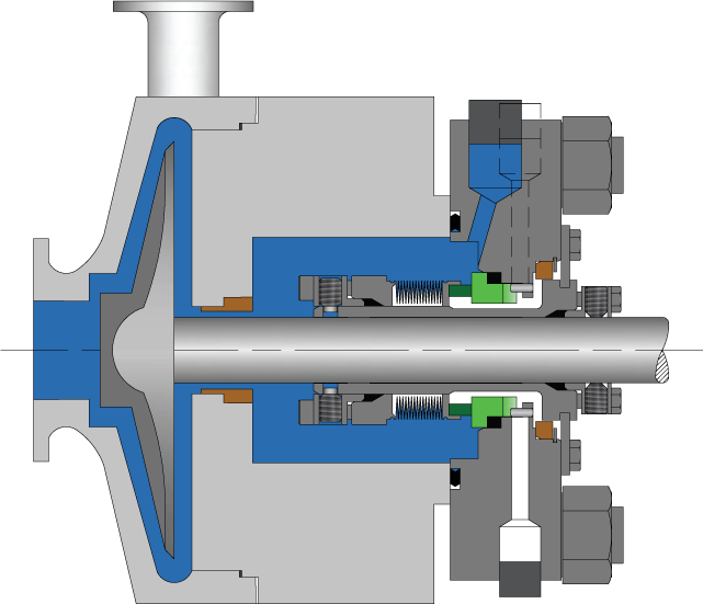
FIG. 1A illustrates an example of a single cartridge seal. The seal 17 is attached to equipment 18 via bolts 19 and surrounds a shaft 26. The seal includes a static o-ring gasket between the seal sleeve and pump shaft or sleeve, as indicated at 1. A static o-ring gasket 2 is provided between the sleeve end bore and a rotary face. A static o-ring gasket 3 is provided between the gland bore and the stationary face. The gland 7 has springs and an o-ring gasket and has a stationary face which is bolted to pump housing to hold the seal in place. The sleeve 8 contains two o-ring gaskets and a rotary face and transmits drive to the rotary face with a drive pin. The inboard rotary face 9 is driven by the seal sleeve which is rotating with the pump shaft which provides primary sealing action by running against the stationary face with a thin layer of lubrication between the faces. The inboard stationary face 11 is held stationary within the seal gland using antirotation lugs and provides a primary sealing action by the rotary face running against it. The set screws 13 are contained within the drive collar and transmit drive to the seal sleeve by engaging the pump shaft or sleeve through holes in the sleeve. A flat gasket 14 provides a gasket seal between the gland and pump housing face. A snap-ring 15 engages a groove in the sleeve to hold the drive collar with the set screws in place. Springs 16 are contained within the seal gland and provide mechanical force to keep the inboard stationary face loaded against the rotary face.
FIG. 1B illustrates a double cartridge seal. The double cartridge includes the same parts as the single cartridge and an o-ring 5 which provides a static o-ring gasket between a drive collar and the inside diameter of the outboard rotary face. A static o-ring gasket 6 is located between the drive collar and the outside diameter of the sleeve. The outboard rotary faces 10 are driven by a pin in the drive collar which rotates with the pump shaft providing primary sealing action by running against the outboard stationary face with a thin layer of lubrication between the faces. An outboard stationary face 12 is held stationary within the outboard side of the gland using antirotation pins providing primary sealing action by having the outboard rotary face running against it.
Such cartridge seals are constructed from various components into a unitized design. Some components typically are manufactured from either “bar stock” or “tubing,” or from castings. Casted parts generally cost less than parts manufactured from bar stock. Castings may be designed such that a small number of castings may be compatible for a given set of equipment through an analysis of equipment profiles.
FIG. 2 illustrates a block diagram of a system 20 in one embodiment. The system includes an input module 21 which enables the user to select a customer or add a customer to a database, select a process fluid, enter environmental data and select from three paths through the system. A new customer 43 may be added to the customer database 30. The customer identifier is used to return information about the customer as indicated at 44. From the input module, a user may invoke a seal specifier 22 which selects a seal, recommends materials, allows the user to select either equipment modifications or seal modifications and recommends various features and products. The profile of a selected seal is output as indicated at 40. A new pump definition module 24 also may be activated through the input module 21. This module allows a user to enter information from which a new pump record and pump dimensional profile is created. A compatibility analyzer 26 compares dimensions of the new pump record to seal dimensions in a seal styles database 33. The results from the compatibility analyzer 35 are added to the pump database 31, along with the pump dimensional profile, frame/group, pump sizes, bore type and other compatibility results for other pumps. The input module 21 also allows the user to activate an existing pump selector 25. Information about a pump profile, as indicated at 36, may be used to search a pump database 31 to return profiles 38 of selected pumps.
The pump database 31 includes data which describes a large number of pumps. The database also may specify other kinds of equipment, depending on the kind of mechanical part the system is being used to select. The pump database 31 may include, for each pump, data describing the seal sizes for the pump, the frame or group by which the group is categorized, the pump size, the bore type, a complete dimensional profile, and compatibility results for seal models.
The seal styles database 33 includes a dimensional profile of each seal, graphical drawings, materials available for each seal, and other features and additional products available, along with CNC programs and templates 47. In particular, the seal styles database 33 defines metal materials, face materials, and elastomers for each seal style. It also may contain a complete listing of compatible optional features and additional products for each seal. A dimensional profile for each seal as well as a complete set of drawings or graphics for each seal model, template CNC programs for the manufacturing process also may be stored in this database 33. Generally, the seal styles database 33 is defined and maintained by a seals manufacturer.
A process fluid database 32 provides characteristics and recommendations of the selected process fluid provided by the input module 21, as shown in 37. In particular, the process fluids database 32 includes, for each fluid which may be pumped by the equipment, a material compatibility rating for the pump materials, a recommended seal type, recommended materials, and a recommended American Petroleum Institute (API) plan for the seal. Generally, the process fluids database 32 is defined and maintained by the seal manufacturer.
The profile of the selected pump 38, the characteristics and recommendations of process fluid 37 and the dimensions and graphics of a selected seal 39 from a seal styles database are provided to a seal specifier 22, discussed above. The seal specifier 22 uses the chemical characteristics and recommendations 37 from the process fluid database 32, the pump profile selected 28 and the seal dimensional profile 39 to create a profile of a selected seal 40. The profile of a selected seal 40, dimensions and graphics of a seal 39 and a pump profile and results of compatibility analyzer 41 are input to the design center 28. The design center uses pump and seal profiles to draw and calculate dimensions for modified and custom seal components, and outputs results as indicated at 42.
The CNC programs and templates 47 from the seal styles database 22 for the selected seal and the result of the design center 42 are input to a manufacturing center 29 and proposal generator 23. This manufacturing center uses results from the design center to create custom manufacturing prints and programs for each of the modified or custom components, as output at 46, for manufacturing the components. In particular, the manufacturing center uses the dimensions defined by the design center 42 and inserts them into template CNC programs 47 from the seal styles database 33 for the selected seal. These programs are downloaded directly into CNC machinery for manufacturing of a component.
The results of the design center 42 also are provided to a proposal generator 23. The proposal generator 23 also receives address and discount information 45 about the selected customer. The proposal generator produces drawings, price, modification notes, warnings, bills of materials, order forms, dimension verification forms and plants standardization surveys, as described below, from which quotation proposals 51 may be produced. An order processing module 50 receives a quotation proposal 51 to produce an order 52 which is provided to the manufacturing center 29.
In order to create the pump profile and seal styles databases, information from standard pumps and seals may be input into the database. The compatibility analyzer then may be executed to determine the compatibility of each pump with each seal. The results of these compatibility analyses may be stored in the pump profile database. In this manner, known modifications for common seals and common pumps may be stored in the database and need not be recomputed. As a general process, any modifications created by this system may be stored in the database for future use.
In operation, a user activates the input module 21 to enter new customer data or to select an existing customer, to enter environmental data and to select the relevant process fluid. The user then may proceed to the seal specifier 22 to select a seal if the desired seal is known. If the part number for the desired seal is not known, and if the pump is defined within the database 31, then the user may activate the existing pump selector 25. Pump selector 25 may search for a pump in the database based on dimensions, frame or group, part number, or other information. If the pump is not in the pump database, the new pump definition module 24 may be activated. When the new pump definition module 24 is used to add a new pump to the database, the compatibility analyzer 26 performs a compatibility analysis based on the definition of the new pump with respect to the various seals in the seal database and updates the pump database 31 to include this data relating to the new pump. After a pump has been defined or selected, the seal specifier 22 may be activated by the user. The seal specifier 22 then accesses the pump database 31, which includes the definition and compatibility analysis for any existing and new pumps defined by the user. The seal specifier 22 also allows the user to the select seal style, or to review a list of all seals. The seal database also may include a cross-reference to indicate that the seal is a replacement for another manufacturer"s seal.
When no standard seal model fits the selected pump, the user has two options. First, the seal specifier 22 provides a special seal design which fits the equipment without modifications to the equipment. Second, the seal specifier 22 may provide a standard seal and specifications of modifications to be made to the equipment to fit the seal.
The seal specifier 22, using the process fluids database recommends materials and may provide a list of all available materials with compatibility ratings for the seal model in use with the specified process fluid.
After the seal specifier 22 has completed a profile of the selected seal, the design center 28 designs, draws and calculates dimensions for each component of the seal, which are then provided to proposal generator 23.
The proposal generator 23 generates output forms, including information such as drawings, dimensions, price quotations, modification notes for the seal or the equipment, warnings, bills of materials, a dimension verification form, and an order form. The dimensional verification form is provided to the user to ensure that the user has properly measured dimensions of the equipment.
The results from the design center also are used in the manufacturing center. The manufacturing center retrieves template CNC programs which are part of the seal styles database. The template programs include machining operations without dimensions. The dimensions are inserted from the information from the design center. After modification, the templates CNC programs with the dimensions of the seal are downloaded into CNC machinery to produce the new seal.
In particular, the system may be implemented as a combination of software and data that may be installed and operated by a user on one or more machines to provide all functions relating to mechanical seal selection. In this arrangement, data for the various databases may change over time and a manufacturer would periodically provide updates to the users of the software and data Such updates may be provided using any means of electronic transmission or through delivery of a storage medium containing the information. Also in this embodiment, a manufacturer may wish to collect changes to databases made by their users in order to continually update their databases of pumps, process, fluids and seals.
In another embodiment, the seal specifier 22 is provided to a user. The compatibility analyzer 26, design center 28 and manufacturing center 29 may be maintained by a manufacturer. In another embodiment, the seal specifier and compatibility analyzer may be accessible to a user. In this embodiment, the design center 28 and manufacturing center 29 are maintained by the manufacturer. In another embodiment, a user may have access to the user interface of the seal specifier, for example, through a public computer network such as the Internet, or through another remote access medium. In another embodiment, the seal specifier 22, the compatibility analyzer 26 and the design center 28 may be provided to a user. The manufacturing center 29 in such an instance may be maintained by the manufacturer. Various other embodiments also are possible.
FIGS. 3A and 3B illustrate in more detail a process through which a seal may be selected using the system of Figs. The process begins by the user entering customer data in step 60. FIGS. 4 and 5 illustrate graphical user interfaces for this function. Also using a display such as shown in FIG. 4, environmental data and process fluids may be defined in step 61. After input of this information, the user may choose among a number of selection methods in step 62. In this embodiment, there are three selection methods. The first selection method involves simply selecting a known seal, in step 63, which is described in more detail below in connection with FIG. 6. A pump may be searched from an existing database in step 64, which is described in more detail below in connection with at least FIGS. 7 and 8. A new pump may also be defined in step 65, as is described below in connection with at least FIGS. 9 and 10.
When a seal is selected in step 63, a quote proposal is generated in step 80, which is described in more detail below in connection with FIGS. 30 through 36. An order entry department activates a manufacturing center to produce an order in step 81. A manufacturing center then may create special manufacturing and scheduling prints for the manufacturing processes, may select material to be used, may order materials if necessary, and may create programs for computer numerically controlled equipment for manufacturing modified or custom components. These manufacturing center operations are described in more detail below in connection with FIG. 37.
If the user elects to search for a pump from an existing database, in step 64, the user then may choose from a variety of seal selection methods, as indicated in step 67. A graphical user interface for making this selection in one embodiment is shown in FIGS. 14 and 15. One method is to select from available seal models in step 68. This method is described in more detail below in connection with FIG. 16. A compatibility analysis is then performed in step 72. The materials of construction and process fluid rating are selected and checked in step 75, which is described in more detail below in connection with FIG. 15. A component type seal also may be selected in step 71, as another selection method, which is described in more detail below in connection with FIG. 20.
Another seal selection method is to select the seal family in step 69. This step is described in more detail below in connection with FIG. 19. A seal model is then recommended in step 73. Another method involves recommending a model from any family of seals in step 70. This step is described in more detail below in connection with FIG. 17. Either of the last two methods concludes with a recommendation of materials and construction and API plans based on the process plan.
All of these methods of selecting a seal conclude with step 75 of selecting materials of construction and checking other process and fluid ratings, which is described in more detail below in connection with FIG. 15.
After step 75, it is then determined if a standard seal fits the indicated equipment in step 76. If not, a modification strategy is selected in step 77, which is described in more detail below in connection with FIG. 22. Optional features and additional products are recommended in step 78, which is described below in more detail in connection with FIG. 23. In step 79, a design center designs, draws and calculates dimensions for the selected items. This step is described in more detail below in connection with FIG. 24.
Each of the steps in FIGS. 3A and 3B will now be described in more detail in connection with FIGS. 4 through 37. FIG. 4 is a representation of a screen display 90 which prompts the user to enter customer data and other information. The screen display 90 is segmented into different areas for different data and options selectable by the user. For example, in customer data area 91, the user may select a user ID and customer ID, if the customer database 30 (FIG. 2) includes a description of the customer. If the customer has been granted a discount, the system displays the amount of the discount within the customer data area 91. At any time, the user may select any help icon 101, for which the system may provide textural information to guide the user through the seal selection process. The system also may have a training program to educate the system user on how to use the screens of the program or to provide technical assistance.
Referring again to FIG. 4, as in step 61 of FIG. 3, the user defines environmental data and at least one process fluid for which the replacement or new seal will be used, by filling out sections of environmental data entry area 93. The data includes a name of the process fluid. If the defined process fluid is not found within the process fluids database 32, the user may select the “chemical not found” icon 94. The system then displays guidelines for proceeding, or prompts the user to contact the manufacturer to define the applicable process fluid. In addition, the manufacturer may populate the process fluid database 32 if desired.
In the first method, the user activates the Path 1 icon 96 within the seal information area 95, and is shown the quick path screen (FIG. 6) allowing the user to select the seal directly (step 63 of FIG. 3). A second selection method selectable by the user by selecting icon 100 is to search from the existing pump database (step 64 of FIG. 3). Details of this option are described in more detail in connection with the flow chart of FIG. 7. A third selection option is to define a new pump (step 65 in FIG. 3), the details of which are described below in connection with the flow chart of FIG. 9 and screen display of FIG. 10. This path is accessed by selecting icon 97 on FIG. 4.
The first method, activated using icon 96 in FIG. 4, will now be described in more detail in connection with FIG. 6. Through a series of drop down menus, the user is prompted to enter a part number, for seals, kits, faces or other part in area 120. In this embodiment, the first digit represents the metallurgy; the second digit represents the elastomer (o-ring); the next four digits represent the seal model number; the next four digits represent the seal size; the next digit represents the inboard face; and the final digit (only on double seals) represents the outboard face material. The user is then prompted in area 121 to select optional features. In area 122, spare parts kits and factory repairs are quoted. Area 123 displays additional products available, from which the user may select. The quote proposal on the item selected is provided to the user, as described below in connection with FIG. 30. This path prepares a quote proposal for any seals. With this option, the compatibility analysis between the pump and the selected seal is not performed. However, this option allows experts to use the system quickly and efficiently to obtain a price quote, or untrained individuals to select a seal using a part number
After a pump model has been selected, the user has several for searching for the pump profile. In particular, the user may search the database by seal size, frame or group, or by pump size, in step 134. The option of searching by serial number also may be provided. If an identification tag is not readable and/or original paperwork about the pump is lost, at least one of the three search engines should enable a positive identification of the pump. In step 135, the system displays a list of matching seal sizes, frame or group, or pump sizes, depending upon the search option selected. The user then selects the choice which matches the equipment or selects unknown for a complete listing in step 136.
Another method for seal selection, activated through icon 97 in FIG. 4, will now be described in connection with FIGS. 9 and 10. In one embodiment, a screen such as shown in FIG. 10 is used to receive data defined by the user. In step 150 (FIG. 9), the system assigns a new pump identifier (area 170 of FIG. 10) which allows the system to provide a unique definition of the pump under consideration. In step 151, the user enters, if known, information such as the name of the pump manufacturer into area 171, the model in area 172, the frame or group into area 173, the pump sizes available into area 174, and the solid shaft/sleeve outer diameter into area 175. The system recommends the standard default gland type or allows the user to select a special gland type in area 176, (step 152) only if the user is sure the standard default gland does not fit. The customer may visually select a gland type by viewing the visual geometry of the existing seal or the equipment the seal fits on. The user then may select any gland type. Example glands are, but are not limited, to standard, round with drill holes, round with rectangular bolt patterns, glands with flats and drill holes, special elliptical designs, round glands with slots on horizontal, special bar stock designs, round glands with multiple bolt holes, and standard glands modified.
In step 153, the system displays a bolt pattern graphic in area 177 for the defined gland type and an equipment cutaway drawing in area 178, as shown in FIG. 10. The user defines the equipment type (step 154) in area 179, defines the pump bore type (step 155) in area 180, defines the sleeve style, e.g., packing or seal sleeve, (step 156) in area 181. The system recommends the standard default sleeve type or allows the user to select a special sleeve type in area 182, (step 157) only if the user is sure the standard default sleeve does not fit. The customer may decide visually on the sleeve type, for example by viewing the visual geometry of the existing seal or the equipment. The user then may select any sleeve type. Example sleeve types include, but are not limited to: standard sleeve, straight sleeve with non-standard ID, hook sleeve, step sleeve, sleeve extensions, and special sleeve designs. The user then may define special gland features if requested (step 158) in area 183. Example gland features include, but are not limited to, ID Pilot Gland, OD Pilot Gland, and O-Ring Groove Gland.
The user then defines major dimensions of the pump (step 159) in areas 184-200. The major dimensions include box bore in area 184, box depth in area 185, first obstruction in area 186, number of bolts in area 187, bolt spacing in area 188, bolting size in area 189, stud projection from box face in area 190, bolt circles in area 191, horizontal distance in area 192, vertical distance in area 193, existing gland outer diameter in area 194, maximum gland outer diameter in area 195, ID pilot in area 196, ID or OD pilot depth in area 197, OD pilot in area 198, sleeve extends from the face in area 199, sleeve steps to shaft size in area 200. Horizontal and vertical distances are input only for glands with rectangle bolt patterns. The system may automatically enter “N/A” if a round bolt pattern has been selected. The locations of these measurements are displayed on the bolt pattern 177 and cutaway drawing 178, so that a user may take the measurements without undue training. A help icon 203 also may be used to present instructions about how to obtain valid information for the dimensions. The manufacturer, model and Solid Shaft/Sleeve OD also are input. The remainder of the information is optional. In area 201, the user is prompted to answer questions relating to the sources used to obtain the equipment dimensions. Example: physical measurements, from equipment prints, or from seal prints. The user also is prompted to confirm the equipment is still in its original state and if not, to explain the modifications made in area 202.
After adding the pump data in the database, in step 161, the system analyzes the pump dimensions provided in step 159 to determine the most compatible seal model for each seal type. FIG. 12, which is described in more detail below, represents a seal dimensional profile which may be used for this analysis.
All seals may be categorized by seal type, for example single cartridge seal, double cartridge seal, double cartridge seal with pumping ring, single cartridge model 3500 seal, metal bellows for chemical service, metal bellows for high temperature service, high pressure cartridge designs, double cartridge (gas barrier design), dry running single design for mixers, double cartridge for mixer with liquid lubrication or gas barrier design, split mechanical seals, component type seals, API (American Petroleum Institute) design seals, etc. The system accommodates any commercially available seal types and can be expanded to accommodate new seal types. The examples below are for common seal types: Single, Double, Double with Pumping Ring, 3500. Other type seals are not shown but may be calculated in a similar manner.
For single, double and double with a pumping ring, the following formula is used. If the seal size is less than 0.896 or greater than 5.020 no recommendation is made. If the seal size is between 1.021 and 1.145 or between 1.271 and 1.395, a narrow cross section seal is recommended. If the actual gasket outer diameter (FIG. 12, area 274) minus the box bore (FIG. 10, area 184) is greater than zero, the standard model is recommended. If the result was less than zero the larger bore model is recommended.
If a model is determined to be compatible in step 161, the system assigns a model number in area 210 of FIG. 11, (step 162). If no model is recommended, in step 163 the system assigns an alternate seal type in area 211 of FIG. 11. For example, if Style 3500 is not available in a 4.00 inch size, the system recommends an alternate of the standard single type seal.
In step 164, the compatibility analyzer performs a compatibility analysis, which is described below in connection with FIG. 13, for each potential seal model. In step 165, they system sets the “Seal Fits Equipment” notes (area 214), and the “Equipment Fits Seal” notes (area 215), and stores the results of the compatibility analysis in the pump database (areas 216-229). These steps complete step 66 of FIG. 3A.
An example of a seal dimensional profile is shown in FIG. 12. The profile includes, but is not limited to having, the seal size 250, minimum bore 251, maximum bore 252, inside length 253, outside length 254, minimum bolt circle for several bolt sizes, such as ⅜ (255), ½ (256), ⅝ (257), ¾ (258), the slot width 259, gland outer diameter 260, gland flat 261, sleeve outer diameter 262, gland length 263, bar gland length 264, o-ring position 1 (265), position 2 (266), position 3 (267), position 4 (268), position 5 (269), position 6 (270), actual casting outer diameter 271, actual slot inner diameter 272, outer diameter of shroud on casting 273, actual gasket outer diameter 274, counter bore in gland 275, bar shroud outer diameter 276, inboard balance diameter 277, outboard balance diameter 278, outboard internal obstruction 279, inboard internal obstruction 280, and internal depth obstruction 281. Additional fields may be displayed or added for other seal types where appropriate.
The compatibility analyzer performs a series of calculations, which is described in more detail below in connection with FIG. 13, which compare the pump dimensions, supplied by the user using the interface FIG. 10, to the seal profile dimensions, shown in FIG. 12.
These calculations are performed to determine if a standard or special design should be used to fit the pump. The results of the calculations are stored in the pump database and used later in the design center to engineer and design special seals and components. If modifications are suggested, the system recommends two options:
FIG. 11 illustrates a display for the results of the compatibility analyzer. Section 231 and 232 reflects the information entered by the user using the interface of FIG. 10. Sections 210-229 display information generated by the compatibility analyzer. In particular, this information may include the gland type in box 212, sleeve type in box 213, “Seal fits equipment” notes in box 214, “Equipment fits seal” notes in box 215, and the values of various calculations in boxes 216-229, which will now be described in connection with FIG. 13.
In FIG. 13, in step 300, the system matches the actual shaft/seal size from FIG. 10 area 175 to standard seal sizes from FIG. 12, area 250. If a match is found, the system continues to the “Seal fits in box” calculation, step 305. If an exact match is not found, in step 301 it is determined if the shaft/seal size is within the range of tolerance, e.g., +0.001 to −0.005, of a standard seal size. If the size is within this range, processing continues with step 305.
If the size is not within the desired range of the standard seal size, it is then determined, in step 302, if the shaft size is within the range of −0.104 to +0.020. If the size is within this range, the sleeve type is set to 2 in box 213 of FIG. 11, a modification note 501D is set in box 215 of FIG. 11 and the results are stored in box 229 in step 303.
If the shaft size matches the entered seal size, or is within a desired range, as determined in steps 300, 301 and 302, processing continues with step 305. In step 305, it is determined if the box bore dimension (FIG. 10, area 184) is blank. If it is blank, the verification note 502A, in sections 214 and 215 of FIG. 11, is set in step 306 and processing continues to step 309.
In step 355, it is determined if the existing gland outer diameter (FIG. 10, area 192) is blank. If blank, processing continues with step 357. If not blank, in step 356 it is determined if the difference between the outer diameter of the existing gland and the actual casting outer diameter is positive. The actual casting outer diameter is from FIG. 12, area 271. If the result is positive, processing continues with step 361. If negative, processing continues with step 357.
In step 357, it is determined if the maximum gland outer diameter is blank. If blank, in step 358


 8613371530291