
api plan 61 mechanical seal quotation
With over 100 years’ experience in developing technologies that optimize rotating equipment performance, John Crane understands mechanical seals. We know that you need reliable seal performance to maximize process efficiencies while meeting production targets and constantly evolving, stringent operational requirements. Our expert engineers have designed a range of fluid control systems that create the optimal operating environment to enable the dependable performance you expect from a John Crane seal. No matter what the process fluid, from liquids to gases, cryogenic to boiling and abrasive to the purest finished product, our range of barrier fluid reservoirs, heat exchangers, abrasive separators and pump seal gas control panels support the most complete spectrum of industrial processes. Compliant with global industry codes such as API, ASME VIII and ASME B31.3, our systems can also be designed and built to meet regional specifications such as AD2000, ATEX, CE, PED, SELO and GOST.
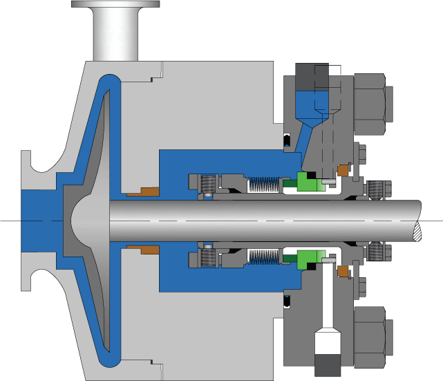
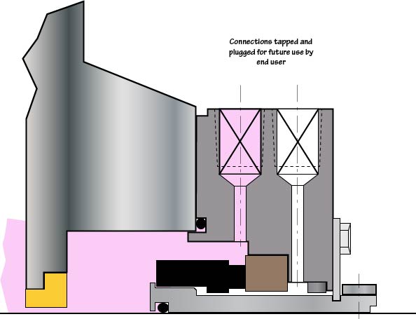
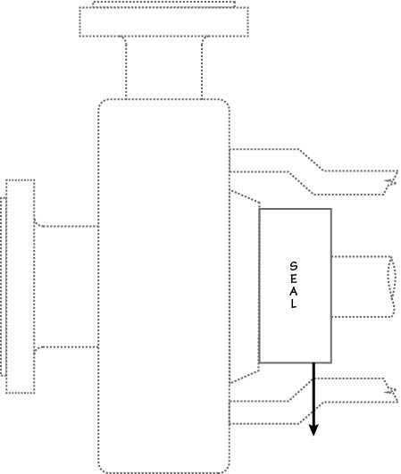
In Plan 61, only connections are supplied. Plan 61is sometimes used if the end user has a special or as yet undefined future use for the connections. Flush, Quench and Drain connections are supplied and plugged with plastic plugs.
Single seal, cartridge design, independent from the direction of rotation, multi-spring. The seal acc. to EN ISO 21049 (API 682): type A, category 2 or 3, arrangement 1, configuration 1CW-FL (with a floating carbon throttle bushing).
Established in the year 2016, Flowway Teknik Private Limited are leading Exporter and Manufacturer of Mechanical Seal, Mechanical Pump Seal, Swing Joints, etc. Today, it provides the most complete selection of engineered mechanical seals and sealing support systems. Our products are recognized as a trusted brand in a process industry.read more... Brochure
With highly driven ethnically excellence, our organization is actively committed to offer a wide assortment of Mechanical Seal Support System to our valuable clients. Offered support system is manufactured using the quality grade basic material and high-end technology. Provided support system is widely used in variousread more...
EagleBurgmann"s product portfolio includes almost all types of mechanical seals, like API 682 Qualified Seals, Pusher Seals, Metal Bellows Seals, Dry Gas Seals for compressors, Split Seals, Slurry Seals, Containment Seals, dry and wet running Agitator Seals, Rubber Bellows Seals, Teflon Bellows Seals, Rotary Joints, etc. Ruggedread more...
The Spill-Ex Universal Support System is effective to control belt sagging between the idlers and thus improve the performance of the skirt board sealing system. The support system is of Universal type which is fully adjustable to suit different belt widths, trough angles and conveyor profile encountered at various materialread more...
Metaltek is the largest manufacturer & exporter of Seal Support Systems in India, manufacturing Systems with Pressure Rating from #300 to #2500. We are supplying systems to all the leading Mechanical Seal & API Pump manufacturers in India.
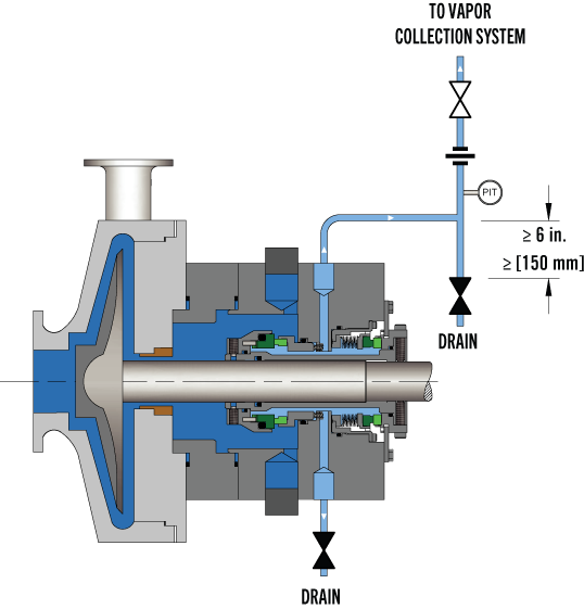
n API Plan 52 external reservoir provides buffer fluid for the outer seal of an un-pressurized dual seal arrangement ( Arrangement 2). During operation an internal pumping ring provides circulation. The reservoir is connected to a vapour recovery system and is maintained at a pressure less than the pressure in the seal chamber.read more...
When discussing slurry pump seal support plans it seems that the terms “Flush” and “Quench” are often confused and or misused. With the concept being slightly different for mechanical seal boxes vs packed seal boxes I will separate these, discussing each in turn.
The basic mechanical seal flush plan is very simple. It calls for a clear/clean liquid, usually water, to be introduced into the space between the actual seal and an impeller side exit restriction. The flush liquid is introduced at a pressure above that of the pumpage, thus assuring a positive outward flow/flush and a clean operating environment for the mechanical seal. This is illustrated below.
The definition of a flush is a “fluid which is introduced into the seal chamber on the process fluid side in close proximity to the seal faces and typically used for cooling and lubricating the seal faces.
When flushing is required, Toyo recommends the use of an API plan 32 seal piping arrangement as it is better suited in services containing solids or contaminants which could damage the seal faces if recirculated in the flush media.
The Plan 32 typically uses a clear clean fluid supplied from an external source delivered to the primary seal faces on the process fluid side of the seal. With the use of a close-clearance throat bushing, the stuffing box can be back pressured to an elevated pressure ensuring the flushing fluid will not flash across the seal faces.
A quench plan, as the name indicates, is designed to quench or cool the seal. It is normally used if short periods of dry running are expected. As illustrated bellow, the fluid is introduced into the area between the back of the seal faces and the close fit exit on the drive side of the pump.
API 682 3rd Edition defines a quench as a“neutral fluid, usually water or steam, is introduced on the atmospheric side of the seal to retard formation of solids that may interfere with movement, or for other purposes.”
Some quench seal plans replace the close fit exit restriction with a secondary seal and a top exiting port that can be plumbed to capture the spent quench fluid and route it away from the rotating assembly. The principal is however just the same, we are trying to cool the seal not in any way flush the seal.
The primary goal of all flush water plans is to preclude the pumpage from contaminating the seals. As such flush water plans for packed boxes are very similar to that of mechanical seal boxes. However, as illustrated below there are some obvious mechanical differences. The most striking difference is the addition of a seal (packing) located between the injection port and the exit restriction. This minimizes the volume of flush liquid consumed.
From an operational standpoint, the packed box differs as it requires some leakage to assure lubrication and prevent heat build-up. The mechanical seal box should have no leakage.
With a standard flush plan, flow is typically adjusted by compressing the packing until a few drops are observed leaking out of the seal on the drive side. On a quench plan, flow rate is set by adjusting an inlet valve while at the same time using a valve on the exhaust side to maintain the correct seal box pressure. If the exit water from the seal box is too hot, flow rate is increased until exit water is cool while still maintaining the proper seal box pressure.
I hope this short blog helps clear up some of the confusion with seal flush plans. Before signing off for today, let me confirm the information provided today is general info only. Always refer to the pump manuals for specific details. If still in doubt, our applications team here at Toyo is always willing to support you in any way they can.

After nearly six years of intensive work, the American Petroleum Institute (API) 682 mechanical seal standard is soon to be adopted. Since its introduction in 1994, API 682 has become “the” standard that sets the global tone for the procurement and operation of seal and supply systems for centrifugal pumps in the oil and gas sector as well as in the petrochemical industry. API 682 is a “living” standard that directly incorporates diverse practical experience in its regular updates.
Founded in 1919 and located in Washington, D.C., the API includes close to 500 companies from the oil and gas sector and the petrochemical industry. Since 1924, it has focused on technical standards. To this day, API has adopted roughly 500 standards that address diverse processes and components in detail—which ultimately ensure a maximum of operating and process reliability. API standards, which are clearly defined and in part attached to approval tests, do not take effect only in the U.S. In many cases, they have developed into worldwide industrial standards. API is often considered a synonym for safety and reliability.
Individual standards—including API 682 regulations for mechanical seals and seal supply systems—have become so popular that they have even been referenced in outside industry applications. The authors of the new edition point out that this was never the intention and clarify the actual purpose of the API 682 standards. The standards are for seal systems in pumps—not in agitators or compressors—and for oil and gas and petro chemistry—not for water supply or the food sector.
Initial information about mechanical seals was originally provided in the API 610 pump standard. During the 1990s, API 682 developed into a separate, more comprehensive standard for mechanical seals and supply systems. The API 682 standard is continually maintained and updated by end users and manufacturers. Another quality of API 682 is that it does not typically permit only a single technical solution. In addition to proven and tested standard solutions (defaults), the regulations also deliberately list alternatives (options) and even allow customized solutions (engineered solutions). This diversity is demonstrated more clearly in this edition than in previous ones.
The composition of the 25-member task force is representative of the practical way in which API approaches the topic of seals. Since 2006, the task force has been updating the 3rd Edition of API 682 that took effect in 2004 and is still valid. In addition to leading seal system manufacturers, the American-European expert panel—which intentionally counted on non-API member collaboration—also included renowned planning companies and representatives from some of the largest mineral oil groups, who are users of seal solutions.
While the currently valid API 682 edition included approximately 200 pages, the 4th Edition is 260 pages. The revised edition is organized into a body of text with 11 chapters and detailed annexes with a significantly expanded scope. For example, Annex I provides detailed information on more than 20 pages for API-conform seal qualification tests.
Default seals and options must be tested using five different media and clearly defined operating conditions representative of typical API applications. Together with the described seal designs, this yields a high number of possible test variations. In the process, the expended time per test and seal type can take up to 200 hours. The result for typical industry seal designs is documented in a test certificate and a detailed report. Customer-specific qualification tests can be agreed upon for engineered seals.
Essentially, checked and tested product safety is the core of the standard. The objective of API 682 is continuous operation of at least three years (25,000 operating hours subject to the legally stipulated emission values, or for maximum “screening value” of 1,000 parts per million by volume, EPA Method 21), increased operational reliability and simplified maintenance. The standards defined by API apply exclusively to cartridge systems with a shaft diameter of 20 to 110 millimeters and a defined range of operating conditions.
The 4th Edition also includes the revised product coding system (Annex D). The proven classification parameters “Category,” “Arrangement” and “Type” will be continued. They are listed first in the revised code and provide information about the setup and field of use of the respective API seal. The seal arrangement includes:Arrangement 1—single seals are differentiated
Details regarding the supply system—specified as “Plan”—are in the old and new code. The addition of precise information regarding material selection and shaft diameter is new. This gives more meaning to the code and guarantees a clear specification of the mechanical seal and its operation—from selection to documentation. Industry experts agreed that the expanded coding system will prove itself in practice and endure permanently.
The selection process of an API seal system is complicated. Several flow charts and tables on more than 10 pages are dedicated to this topic in the new edition. To provide more precision in the technical selection process when determining the arrangement, an alternative selection tool (Annex A.4) has been included in the 4th Edition for the first time. This method is based on the established “Risk & Hazard Code” and has been tested in practice.
The starting point is the pumped medium. Its real hazard potential is accurately recorded and described by the “Hazard & Risk Code” in the “Material Safety Data Sheets.” Decisions can be made quickly and securely, for example, about whether a single seal (Arrangement 1) will suffice, or if a double seal with barrier pressure system is required.
The experience-based, “lived” standard of the API 682 edition is demonstrated by the two silicon carbide (SiC) variants, reaction-bonded silicon carbide and self-sintered silicon carbide, which are treated equally as default materials for sliding surfaces in chemical (Category 1) as well as in refinery/oil and gas applications (Category 2 or 3). Until now, sintered SiC was set for chemical applications because of its superior chemical stability, whereas the reaction-bonded variant established itself in the refinery sector. This restrictive allocation was canceled because of practical application examples (best practices) that were brought to the attention of the task force, which called for a course correction.
Plan 53 with a pressurized barrier fluid belongs to the more complicated supply systems. In detail, three types are possible:Plan 53A is the solution with the constructively least amount of effort. The pressure on the barrier medium is generated directly via gas pressurization—normally with nitrogen—in the tank. However, the application has limits, since higher barrier pressures could cause a dissolution of the nitrogen in the barrier medium. The consequence would be the risk of inadequate lubrication in the sealing gap of the mechanical seal. That is why Plans 53B and 53C are used for higher barrier pressure.
Plan 53B uses a clever solution, which makes it popular. Pressurization occurs via an elastomer bladder in the reservoir that separates the nitrogen from the barrier fluid. Pressure monitoring with consideration of the temperature in the bladder accumulator records the values and transfers them to the control room. The fill level with consideration of any temperature impacts is calculated there, and the correct time for refilling the barrier fluid is determined.
A new prescribed refilling interval of at least 28 days has also been included in the 4th Edition of API 682. The fluid reservoir must be large enough to supply the seal with barrier fluid for this entire period—without refilling. To obtain the most compact reservoirs, the seal manufacturers are required to find optimized system solutions with minimal leakage values for the barrier medium.
Also, Plans 03, 55, 65A, 65B, 66A, 66B and 99 have been newly included in the regulations and, along with the already existing plans, are described in detail in Annex G.
The transition to transmitters as default is illustrative: the API specifications primarily concern operating and process reliability and only then consider economic viability. This universal application is also verified by the decision of the task force to permit only seamless pipes in the future for “Piping” for the supply systems. The use of welded pipes, which would be less expensive, was considered unacceptable.
The task force also addressed the topic of heat resistance of the instrumentation used in supply systems pragmatically. In the past, frequent debates occurred regarding whether supply systems for high-temperature applications—for example, a 400 C approved pump—have to be equipped with special instrumentation for high temperatures. Now the temperature specification for the instrumentation has been limited to 100 C. If instruments with higher temperature limits are required in the future, the customer has to inform the seal vendor accordingly.
The essential improvements, in addition to the technical supplements and updates, are the clear structures of the latest API regulation. The body of the text was tightened and structured appropriately, whereas technical details and background information were placed in the annexes. Some of the wording in individual chapters was revised to improve understanding.
The improved user friendliness is shown in Annex E, which addresses structured communication and data exchange between suppliers and customers. Descriptions that previously encompassed many pages in API 682 are now bundled into two compact checklists in the 4th Edition. The first list systematically describes what must be considered for inquiries and quotations. It specifies the data that needs to be provided and the additional information and documents with which it must be combined. For example, seal systems that deviate from standardized API solutions must be shown separately. Annex E is completed by a second checklist that shows in which order the documentation is necessary.
Apart from the numerous technical updates and improved user friendliness, one detail is visually the most striking innovation of this edition: all mechanical seals are equipped with red plugs in the supply connections of the seal gland upon delivery. Until the unit is installed, these plastic closures prevent the ingress of dirt in the seal. During operation, the connections are either assigned to pipelines, or the plastic plugs are replaced with enclosed metal plugs. An additional benefit is that the 4th Edition API seals are quickly identified by the red plugs. Editor’s Note: This article was previously published in Upstream Pumping Solutions, July/August 2013.


 8613371530291