
api plan 61 mechanical seal price
Needing your expertise on seal plush plan 11 + 61 to be used on 98wt% Sulfuric Acid Unloading Pump. Original plan is 11 + 62 which is better. However because water or steam is not allowed (not recommendable) as a quenching media because water or condensate will react with the process fluid (sulfuric acid)original plan was changed. Is this reliable?
11+61 (recommendation of the pump vendor because water or steam is not allowed (not recommendable) as a quenching media because water or condensate will react with the process fluid (sulfuric acid).

The API plans presented in this section are developed in accordance with the API 682, 3 revision / API 610, 10 revision standard. This is the standard scheme of the drilling pipes, which are widely used in industry. It is possible to customize these plans to meet the needs of customers.
The flushing of the seal from the outlet to the seal chamber via the aperture and flushing the seals from the seal chamber to the inlet through the diaphragm
Diagram of the system for ensuring the operation of a single seal with an impeller that creates fluid circulation through the stuffing box along an Autonomous circuit.
If the pressure in the oil seal chamber of the pump is less than the design pressure of the tank (4mpa), the installation of a safety valve on the tank pipelines is not required.
"Tandem" type mechanical seals can be used both with a refrigerator at the pump"s working medium temperature up to 400 °C, and without it at the working medium temperature up to 150 °C.
Diagram of the system for ensuring the operability of a double seal with a tank. The system operates at constant maintenance of the pressure of the shut-off fluid (pressure in the tank) within:
At pump working medium temperatures up to 150°C seals are used without a refrigerator, at the temperature of the pumped medium 150...400°C-with a refrigerator.
For servicing seals of a group of pumps that perform the same task and are located close to each other, it is possible to use the system diagram shown below.
The most commonly used scheme is a system with the supply of shut-off fluid from a separate pipeline with an overpressure m through the seal of the threads.
At pump working medium temperatures up to 150°C seals are used without a refrigerator, at the temperature of the pumped medium 150...400°C-with a refrigerator.
For condensate pumps, where dry operation of the mechanical seals is not excluded, the guaranteed supply of the shut-off fluid can be carried out according to the following scheme.
At pump working medium temperatures up to 150°C seals are used without a refrigerator, at the temperature of the pumped medium 150...400°C-with a refrigerator.
API plan 65 allows you to determine the volume of leaks through the mechanical seal. If the friction pair breaks through, the external strapping tank is equipped with an upper-level alarm that will trigger as soon as the liquid level in the tank increases.
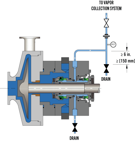
Pumping processes involving hazardous or toxic fluids often utilize dual mechanical seals to ensure operator safety and compliance with environmental regulations. The American Petroleum Institute (API) Standard 682 classifies dual mechanical seals into two categories— pressured and unpressured. For unpressurized configurations, a seal flush system, such as API Plan 52, is required for the seal to operate. A buffer fluid is circulated between the inboard and outboard seals to form a “buffer” between the process fluid and environment.
API Plan 52 seal systems are the most commonly used pressurized dual mechanical seal flush systems in Canadian operations. Plan 52 is widely used in oil and gas operations, but can also be used in chemical and petrochemical refining and power generation applications. Let’s take a look into how the API Plan 52 seal system works for centrifugal pumps and applications in oil and gas, chemical and petrochemical refinement, and power generation.
API Plan 52 seal systems employ a seal pot (reservoir) to deliver an unpressurized buffer fluid to the seal chamber and circulate the fluid between the inboard and outboard mechanical seals. A pumping ring is utilized to provide positive circulation through the seal flush system and into the seal. This plan is commonly used with light hydrocarbons or fluids with a high vapour pressure.
In the event of an inboard seal failure, process fluid will leak into the seal chamber, mixing with the buffer fluid. Thus, the selected buffer fluid must be compatible with the process fluid. One challenge with this plan is frictional losses in the buffer fluid inlet and outlet lines. Frictional losses may be minimized through properly selecting tube size, using large radius and/or 45-degree bends, and reducing the length of tubing in the design.
Tubing configuration and geometry, materials of construction, buffer fluid type, and seal pot volume can be determined and configured based on specific pumping and mechanical seal requirements. API Plan 52 seal systems can include cooling coils within the reservoir to maintain the temperature of buffer fluid being delivered to the seal chamber. This plan can also include instrumentation, such as pressure transmitters, level transmitters, and thermometers depending on the given application. Fluid systems vendors should be consulted to determine configuration specifics such as those listed above.
Depending on the application of dual mechanical seal flush systems, there may be benefits in the higher standards of an ASME stamped seal pot as opposed to a seal pot that meets a lower piping standard. ASME stamped vessels can be more easily tracked and maintained through their Canadian Registration Number (CRN).
In oil and gas operations, including steam-assisted gravity drainage (SAGD), API plan 52 can be used for dual mechanical seals for centrifugal pumps in upstream, midstream, and downstream operations with either high vapour pressure or lower vapour pressure fluids. In chemical plants and petrochemical refineries, dual mechanical seals may be used for high vapour pressure fluid applications. For chemical plants where chemicals are extremely hazardous, a more robust sealing system may be implemented. For power generation, API Plan 52 may be used for water pumping applications, such as boiler feedwater pumps and water treatment pumps.
Whether you are looking to implement a new custom-configured API Plan 52 seal system—or you are looking to upgrade your current plan—Field Advisors at Edmonton Valve & Fitting can provide expert consultations to determine how to increase pumping reliability and efficiency. We are well-versed in local pumping applications for industries including oil and gas, chemical and petrochemical refining, and power generation. We also offer ASME stamped seal pots for customers who would like to ensure proper testing and maintenance tracking with a CRN.
To find out more about how Edmonton Valve & Fittingcan provide API Plan 52 seal systems equipped with ASME stamped seal pots, contact our team of advisorsthrough our website or by calling 780-437-0640.
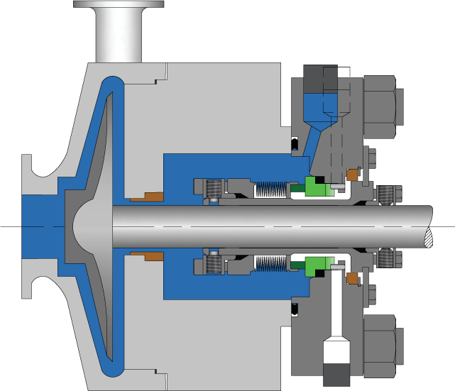
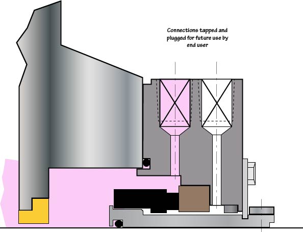
In Plan 61, only connections are supplied. Plan 61is sometimes used if the end user has a special or as yet undefined future use for the connections. Flush, Quench and Drain connections are supplied and plugged with plastic plugs.


 8613371530291