
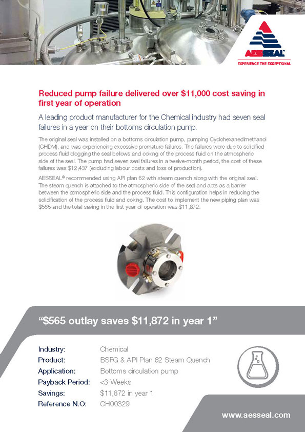
api plan 62 mechanical seal free sample
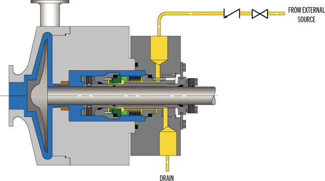
API Plan 62 delivers an external quench fluid to the atmospheric side of the seal. A typical application in a refinery is the prevention of coking on seal faces in hot hydrocarbon service by employing a steam quench. Nitrogen or clean water may also be used to quench or cool and clean the atmospheric side of the seal.
See page 77 of the Mechanical Seal Support Systems Application Guide for additional details and ordering information. Contact your authorized Swagelok sales and service center for information on optional components.

Plan 32 is usually called an “external flush”. It is used in services containing solids or contaminants such that the process stream is difficult to condition in a way that will provide adequate cooling and lubrication to the mechanical seal. Plan 32 is also used when a process stream includes components which may either result in abrasive wear or will impede free movement of critical seal components. In Plan 32, the flush stream is brought in from an external source. This plan should be used in conjunction with a close clearance throat bushing. The bushing can function as a throttling device to maintain an elevated pressure in the stuffing box and as a barrier to isolate the pumped product from the seal chamber. The design of a Plan 32 flush system involves application of hardware and logic that will provide the seal with an environment conducive to long term service, while not compromising the operation and profitability of the process stream.
Sometimes the external source for Plan 32 is more valuable than the service into which it is injected. In such cases, the external source fluid is downgraded. The cost of using Plan 32 can then be quite high. For this reason, flush rates for Plan 32 are usually controlled to be at a minimum rate.
In last month’s beginning to this article, we posited that, although sealing devices account for only a small fraction of the energy consumed by pumps, significant energy conservation can be achieved by elegant sealing practices. In the conclusion that follows, we’ll more closely examine the ways energy content can be made lower in a modern context with mechanical seals by looking into real-world examples and case studies.
In this example, energy efficiency was improved by converting from a single mechanical seal with external flush (Plan 32) to a double seal with barrier system (Plan 53A). The application was at a scotch whiskey distillery where pot ale, a byproduct, is processed in a syrup evaporator to make animal feed.
There are three evaporator circulation pumps, which were fitted with single mechanical seals and a simple Plan 32 flush (see figure 8). Clean fluid from an external source is used to flush the seal chamber, to exclude solids or contaminants, and to reduce the temperature at the seal. It is also used to reduce flashing or air intrusion (in vacuum services) across the seal faces. The main driver for the use of this system is its low initial cost.
A survey of the evaporator system revealed the inefficiency of this flush plan. Syrup was being fed to the evaporator at the rate of 40 gallons per minute, but also being diluted by 0.5 gallons per minute, per pump, of clean flush fluid. The additional 1.5 gallons per minute of liquid into the process meant having to evaporate at least 4 percent more liquid. An analogy is having to walk 26 miles to actually only cover 25.
Conversion to a double seal system with Plan 53A (see figure 9) eliminated the need for seal flush. A small pressurized tank is introduced, containing 2.6 gallons (see figure 11) of barrier fluid. This is circulated either by convection or by a small circulating device built into the seal.
The pressurized barrier fluid provides a clean liquid environment for the inner seal faces and prevents air intrusion to the vacuum. With all three pumps converted (see figure 10), syrup production increased from 97 to 108 tons per hour resulting in a significant reduction in plant running hours. In addition, over 5,000 kilowatt-hours per day was liberated for better use elsewhere.
Any business operating pumps on evaporator systems needs to consider with great care the piping plan used on the pump seals. Plan 32 is often found in many industries, including pulp and paper, sugar production, and chemical process such as nylon manufacturing.
A quench is similar to API Plan 62. Water from an external source is passed between two co-axial seals and away to drain. The water quench is used to prevent solids accumulating on the atmospheric side of the mechanical seal, and can considerably improve seal reliability.
Quench flow rates are typically just under a gallon per minute, per seal installation. In addition to the cost of the water used, the cost and energy consumption of effluent treatment should not be overlooked. The main driver for the use of this system is again its low initial cost
An alternative to this system is to use a barrier system (see figure 13), similar to API Plan 53A. Such systems are self-contained, and more importantly they produce no effluent. If the water supply is connected so as to both pressurize and maintain the level in the tank, no manual intervention is required, and maintenance costs are reduced. An air space can serve as an expansion volume, minimizing the effect of temperature changes. In the event of water supply interruption, the air volume and a check valve maintain pressure until supply is resumed.
This case study involves the conversion of a boiler feed pump from a traditional soft packing gland (see figure 14) to a Plan 23 mechanical seal. To help prevent the rubbing friction damaging the packing, the gland follower would be adjusted to allow a small leakage to flow, typically a slow drip rate. The leakage serves to assist in cooling and lubrication of the gland. As the packing and shaft wear, adjustment will be required to control the leakage rate.
In this example the feed water in the pump was at 250 degrees Fahrenheit (121 degrees Celsius). Losses through the packed gland would need to be made up with water from the treatment plant. The calculation of the energy loss is based the energy required to take the make up water from 50 degrees Fahrenheit (10 degrees Celsius) to feed water temperature of 250 degrees Fahrenheit (121 degrees Celsius). In this instance the boiler plant is gas fired and the heat energy requirement can be translated into a net CO2 contribution. Due to a reduction in plant manning, the gland follower adjustment was only made when the leakage was severe. As a result, the average leakage rate from the pumps was about quarter gallon per minute per gland (see figure 15).
With eight pumps (sixteen glands) leaking on average a gallon every four minutes per gland energy loss is calculated at 124 kilowatts. The plant operates 24 hours per day, 365 days per year, giving an annual energy loss of 1,086,240 kilowatt-hours.
The final case study is the conversion to mechanical seals of a number of large slurry pumps with packed glands. The Debswana operation consists of various diamond mines at Orapa in Botswana, a dry semi-desert area. Essential to the operation are slurry pumps pumping kimberlite and iron silicate. These applications are amongst most abrasive in the slurry-pumping world.
The packed glands on the pumps needed flush water injection (Plan 32) into the process media, at a rate of 15 gallons per minute to exclude slurry from the seal chamber. If the water supply failed, damage occurred to the gland within thirty seconds. Only 10 percent of the flush water is recoverable from the process. A typical train of five pumps consumes over 35 million gallons per year of water from underground sources.
Fitting double seals with water circulation systems (see figure 16) to just eighteen pumps reduced gland water consumption by a significant proportion of the 10 percent total savings required across the site. A further fifty seals and systems have now been installed, covering all the pumps using large volumes of gland service water.
Typically, a bore hole is drilled to over 800 feet with the water table at approximately just under 600 feet. Bore hole pumps are of the helical rotor type and being belt driven are approximately 75 percent efficient. From the reservoir, a multistage pump increases pressure injecting the gland water into the pump casing. The calculated energy consumption of this system is 394,084 kilowatt-hours per year. African power generation is highly dependent on coal. For every kilowatt saving, there is an equivalent atmospheric saving of over 2 pounds of CO2. The double seal conversion utilized a simple tank recirculation system, with total energy consumption of less than 30,000 kilowatt-hours per year. Hence, energy savings of over 350,000 kilowatt-hours per year were achieved.
Consideration of pump seal auxiliary piping systems needs to be given greater priority. The energy indirectly consumed is often ignored, with minimum capital cost being the prime driver when plants are designed. In addition, mature pump installations fitted with traditional high maintenance packing arrangements should be reviewed in terms of plant efficiency. The mechanical seal industry has developed efficient, elegant solutions that provide the operator with higher reliability, lower life-cycle costs, and reduced environmental impact.
AESSeal is a specialist in the design and manufacture of mechanical seals and support systems. AESSeal’s mechanical seals are used in a wide range of pumps and rotating equipment worldwide to prevent liquids and gases escaping into the environment. AESSeal manufactures mechanical seal types to suit all industries and its investment in modular design means that the company provide the best on-time delivery performance in the industry. The AESSeal range of seals, seal support systems, and bearing protectors are all designed to improve pump reliability and reduce maintenance costs. For more information, visit www.aesseal.com.

Pumping of low-temperature and cryogenic fluids requires specific and unique engineering technologies for the shaft sealing system. When correctly applied, these technologies provide the containment and reliability to meet pumping equipment operators’ requirements.
Due to their extreme sub-zero temperatures, low-temperature hydrocarbons and liquefied atmospheric gases pose significant challenges to pumping, and particularly to the specification of their shaft sealing systems. To provide long-term reliability while ensuring that these pumped fluids are safely contained, the designs of the shaft seals used in cold-fluids pumps are often highly specialized.
For example, low temperatures have significant implications for the choice of materials used in the seal construction. Metals become increasingly brittle as the temperature is reduced; therefore, thermal constriction and expansion must be factored. The volatility and flammability of low-temperature hydrocarbons pose special challenges for the design of pump shaft seals, as well as for the release of hazardous emissions to the atmosphere. Liquefied oxygen, with temperatures much colder than these hydrocarbons, is a strong oxidizer and can cause certain materials to spontaneously combust.
Low-temperature hydrocarbons are commonly pumped with API 610 (VS6) vertical multistage double-casing pumps that feature a warming chamber, known as a cofferdam (Fig. 1), which thermally isolates the shaft seal from the cold pumped fluid. Cofferdams enable a greater range of shaft sealing solutions to be used on these pumps, utilizing traditional sealing technology.
A cofferdam is a chamber between the pump discharge and the mechanical seal that is connected to the pump suction, or the vessel from which the pump is drawing suction. Ambient heat surrounding the pump, together with energy from the shaft and bearings, causes the liquid in this chamber to vaporize into a gas, which forms an insulating barrier between the seal and the process fluid. Cofferdams can be incorporated only into vertical pump designs.
Although vertical arrangements are common, various horizontal pumps can also be used. In these types of pumps, the shaft seal is in direct contact with the cold-pumped fluid; therefore, selection of the seal materials for low-temperature operation becomes more critical.
Similar to pumping equipment for low-temperature hydrocarbons, pumps used for liquefied atmospheric gases have a combination of vertical multistage pumps, together with horizontal single-stage pumps. These systems generally do not follow API pump design standards.
However, as the temperatures of liquefied atmospheric gases are much colder than those at which hydrocarbons are pumped, cofferdams cannot be used on these pumps. Although a mixture of vertical and horizontal pumps is commonly used at air liquefaction plants, mobile trailer truck unloading pumps are almost exclusively overhung single-stage pumps, either with direct-drive or speed-increasing gearboxes.
For pump designs where the mechanical seal is immersed in the pumped fluid, the vapor pressure margin in the seal chamber becomes critical. Where the vapor pressure margin is low, the heat energy from the mechanical seal faces can vaporize the fluid around the seal and in the seal interface, resulting in dry running of the seal. In this situation, a dual-pressurized seal is required. A dual-pressurized seal provides a stable barrier fluid to lubricate the seal faces, thereby negating the effect of vaporization of the pumped liquid at the seal faces.
API Plan 53B and 53C barrier systems are commonly selected for dual-pressurized seals to provide a source of warm, clean and stable barrier fluid to the mechanical seal. When an API Plan 53C system is selected, extra care should be taken to ensure that the pressure-amplifying piston and rod seals are insulated from exposure to cold temperatures.
The availability of suitable barrier fluids becomes limited at low temperatures, as the viscosity of many fluids becomes too high at the seal chamber operating temperatures. Mono- and di-ethylene glycol mixtures with water can be used down to temperatures of –29°C (–20°F). Alcohols, such as propanol (propyl alcohol), are suitable for even colder temperatures reaching –70°C (–95°F). Synthetic oils can also be used; however, careful consideration to their pour point is required, and a heating system may be needed to warm the barrier fluid to maintain a suitable viscosity.
When sufficient vapor pressure margin exists within the seal chamber, a dual-unpressurized seal can be selected. Typically, these designs feature a dry-sliding containment seal fitted with API Plan 76, or a combination Plan 72 and 76. These seal arrangements have the advantage of removing the low-temperature limitation of barrier fluid selection.
Pump designs utilizing a cofferdam require a dual-pressurized mechanical seal, as the seal chamber contains no liquid to lubricate the mechanical seal faces.
Icing, due to condensation of atmospheric humidity, can create a problem for sealing systems handling cold hydrocarbons. Since condensing water expands as it freezes, it can interfere with the operation of the mechanical seal if it reaches the seal’s operating mechanism. Extra protection should be applied to equipment exposed to atmospheric elements, such as rain. An API Plan 62 using a dry nitrogen quench can displace atmospheric humidity, thereby protecting the mechanical seal from these effects.
In applications handling liquefied atmospheric gases, pump seal reliability takes precedence when selecting a shaft sealing system. Unlike hydrocarbons, emissions of gases to the environment by liquefied atmospheric gases pose relatively minor hazards and, therefore, are not as critical a factor as seal reliability.
Two commonly employed shaft sealing technologies are used in pumps handling liquefied atmospheric gases: single mechanical seals and segmented bushings.
Single mechanical seals.The most common solution for pumps used in air liquefaction plants and mobile-transportation unloading pumps is the single mechanical seal. The major difference between the two is that the mobile unloading pumps tend to be smaller and often use non-cartridge seals. Cartridge seals are commonly found in larger machinery at air liquefaction plants. Single mechanical seals fall into two sub-categories: contacting wet seals and vaporizing liquid gas seals.
Contacting wet seals utilize a metal bellows to provide elastomer free-axial flexibility. Seal face materials typically include filled tetrafluoroethylene running against a tungsten carbide or hard-coated, stainless steel mating ring.
Vaporizing liquid gas seals (Fig. 2 and Fig. 3), similar in construction to contacting wet seals, feature engineered seal-face topography that allows the controlled vaporization of the pumped atmospheric gas to produce a highly reliable seal that exhibits controlled, low-level leakage rates.
Segmented bushings.A segmented bushings sealing configuration is often found in vertical multi-stage pumps at air liquefaction plants. The design provides a controlled leakage by breaking down the sealed pressure over a series of tightly controlled bushing clearances. Leakage rates are higher than those of mechanical seals; however, these leakage rates are often considered acceptable by this industry.
As mentioned, low temperatures have significant implications for the choice of materials used in the seal construction. This is especially true for elastomers applied in seals for pumps handling low-temperature hydrocarbons. Depending on the material grade used, elastomers have a variety of minimum temperature limits, but none can survive dynamic operation at true cryogenic temperatures.
Engineered polymer seals are an option at temperatures below the limits of elastomers; however, many of these designs will not function with pressure reversals applied to the sealing ring, which may be required in the mechanical seal design when support system failures occur.
Elastomers can survive at significantly lower temperatures below their operational limits when the seals are not in operation (i.e., static); however, they must be warmed up prior to operation. Commissioning of shaft seals containing elastomers must be completed carefully to ensure that equipment is at the correct temperatures before startup. Blowdown—the rapid depressurization of a vessel/pipeline—is one situation that can create excessively low temperatures for mechanical seal elastomers.
Thermal expansion and contraction are also considerations. The cavities in which elastomers or engineered polymer seals are installed will change with decreasing temperatures, as well as the dimensions of sealing elements installed in these cavities. Additionally, clearances between dissimilar materials, such as bushings, will require review. Mechanical seal manufacturers take these factors into consideration during the design of the mechanical seal for these cold services.
Since pumping equipment is often used interchangeably between different atmospheric gases, sealing of liquefied atmospheric gases presents some unique challenges to the selection of materials.
Liquefied oxygen is a strong oxidizer and can cause certain materials to spontaneously combust. Additionally, any organic contaminates on the seal can lead to spontaneous combustion, including metal cutting fluids, fibers from cleaning rags, and even oils from human fingerprints. To meet oxygen service requirements on seals, stringent cleaning specifications must be employed to ensure that the seal is free of any contaminates that may create a fire hazard while in service. Additionally, the materials of construction must include materials that are compatible for use in oxygen service.
Aluminum alloys should be avoided, as they can become hazardous when their protective oxide film is stripped from the material, such as when abrasion occurs. Lubricants used in the assembly and operation of the mechanical seal must be free of hydrocarbons and compatible for use in oxygen service. Packaging of the seal should also be suitable to preserve the cleanliness of the seal prior to installation into the pumping equipment, which must be performed in a suitably clean environment.
Of the many pump mechanical seal applications in use throughout various industries, those that deal with low-temperature and cryogenic processes rank among the more challenging.
It is critical to keep these seals, which handle low-temperature hydrocarbons and liquefied atmospheric gases, in optimal operating condition to ensure that the pumped fluids are safely contained, while providing long-term reliability. HP
Mark Savage is a Product Group Manager at John Crane, responsible for the application, design and development of metal bellows seals for pumps, compressors and rotating machinery. He has worked in the sealing industry for 25 yr and has been involved with the development of best practices for shaft seals and their support systems. Mr. Savage holds a BE degree in mechanical engineering from the University of Sydney, Australia. He is a member of the Fluid Sealing Association and Vice Chair of the Association’s Mechanical Seal Division, Chair of the Mechanical Seal Technical Committee and Vice Chair of the Government Relations Committee. He is also a member of NACE International and the Society of Tribologists and Lubrication Engineers (STLE). Mr. Savage has authored several publications on mechanical seals and support systems and their application to minimize environmental impact.
FLUSH PLANS FOR MECHANICAL SEALS – INTRODUCTIONPumps and seals are being installed into increasingly difficult services. Forsuccessful operation of mechanical seals, the environment and care of the sealsrequire more sophisticated seal chambers and flushing arrangements. This sectionof the Dean Pump Price Book is designed to allow the application and pricing offlush plans suitable to meet the requirements for the mechanical seal.The American Petroleum Institute (API) has defined certain seal flusharrangements known by their plan numbers. Later, the flush plans developed forthe ANSI standard followed suit and placed the digits "73" in front of the API plannumber to achieve some standardization within the process industry. Thus, APIplan 11 becomes and ANSI Plan 7311.Dean Pump has worked with many engineering houses and customers over theyears and has developed a great deal of experience with sealing systems. WhileDean will quote any flush system requirement as requested by a particularcustomer, it has been found that the API/ANSI systems generally meet or exceedmost customer requirements. In addition, Dean Pump developed the Seal GuardEnvironment systems that provide the ultimate mechanical seal flush plan. Forsystems that do not require ANSI/API flush plans, Dean Pump has also includedthe P1200 loop, which is a basic low cost flush plan to satisfy the economyminded customer.The experience of Dean Pump is contained in these price pages. Many of theflush plans are divided into "Toxic/Flammable" and "Non-Toxic/Non-Flammable“services. The information on these plans along with the details described in the"Special Notes" section can be used as a guide in quoting and discussing optionswith customers. The "fine print" in the Special Notes section provides a multitude ofdetails about each flush system. For example, a customer requesting all socketwelded connections can not have every connection welded. Some accommodationmust be made for disconnecting the system. Being aware of the requirements ofthe customer and the manufacturing limitations of the product is extremely helpful.API flush plans are based on the 7 th Edition of API610. Newer versions of the APIspecifications has limited the cooling and flushing options available.Finally, if there are any doubts, questions, or comments, please feel free to call theFactory and the seal vendor.Effective: FEBRUARY 2011 • Replaces: NEWPage 1
SEAL GUARD SYSTEMS – PRODUCT DESCRIPTIONSeal Guard systems are designed to provide a clean liquid for seal flushing thatprovides protection for the mechanical seal in the pump seal chamber. Dean Pumpoffers two basic systems to guard against mechanical seal failure. These systemswill also help to prolong the life of the seal. Both systems are filtration systemsinstalled into the seal flush lines to remove stray abrasive particles which causeseal face wear.Seal Guard A - is designed for filtration only. Particles larger than 10 microns arefiltered from the system using clean-able or replaceable 316SS woven filterelements.Seal Guard B - is designed for high temperature applications and includes a heatexchanger installed ahead of the replaceable filter elements for both filtration andtemperature control.Seal Guard systems are most often used with MIN-FLO Bushings in the pump sealchamber. These bushings restrict the flow from the seal chamber back into thepump during operation and increases the effectiveness of the Seal Guard system.Seal Guards can be used on any pump product line. Their sale is not limited toDean Pump products. Seal Guards are hydrostatically tested but do not meet anyindustrial standard and are not for application to API610 series pumps. Seal Guardapplications must be limited to iron or steel pumps and are not suitable forapplications that require alloy materials.The Seal Guard system is fully described in Bulletin A2000.Effective: FEBRUARY 2011 • Replaces: NEWPage 2
SEAL GUARD SYSTEMS – (See Note #1)Model A Series – Filtration Only (See Note #2)Mounted on Pump BaseplateModel Description List PriceA500T A Series Seal Guard - Filtration - Threaded Connections $4,483A500F A Series Seal Guard - Filtration - Flanged Connections C/FA700T A Series Seal Guard - Filtration - Threaded Connections C/FBD500TB500TModel B Series – Filtration and Cooling (See Notes #2 & #3)Mounted on Separate BaseplateModel Description List PriceBD200T B Series Seal Guard - Cooling & Filtration - $5,248Threaded Connections & Duplex FilterB400T B Series Seal Guard - Cooling & Filtration - $5,248Threaded Connections & Simplex FilterB400F B Series Seal Guard - Cooling & Filtration - C/FFlanged Connections & Simplex FilterB500T B Series Seal Guard - Cooling & Filtration - $6,226Threaded Connections & Simplex FilterBD500T B Series Seal Guard - Cooling & Filtration - $8,240Threaded Connections & Duplex FilterNotes:1. Seal Guard systems are not rated for API application and are suitable for pumps in steel or iron construction only. Do notuse for 316SS or other alloy applications.2. The product description letters and numbers are as follows:First Letter - Seal Guard Series A - Filtration Only; B - Cooling and Filtration. (The letter D following in the second positionindicates a Duplex arrangement.); 3 Digit Number indicates the pressure rating of the Seal Guard system in psi.;Final Letter: T - Threaded Construction; F - Flanged Construction3. The heat exchangers provided for Seal Guard B are furnished with a steel shell and 316SS tube as standard.Effective: FEBRUARY 2011 • Replaces: NEWPage 3
DEAN P1200 ECONOMY FLUSH PLAN FOR PROCESS PUMPSPlan Description:Dean Plan P1200 systems include piping (or tubing) from the pumpdischarge gauge connection to the seal flush connection on the pumpbackhead or seal gland. These plans include all piping and/or tubing.List Prices (Notes 1 & 3)Carbon SteelCarbon SteelFitted 316SS Pipe 316SS PipeSystem Description (Note #2) Tubing Threaded ThreadedRecirculation of Pumpage from Pump Case toP1200 Seal Without Orifice (Similar to API Plan 11 orANSI Plan 7311) VALVE NOT INCLUDED$216 $329 $456 $692Valve Valve for Recirculation Line $205 $762 $205 $762General Notes:1. For all other flush plans, refer to API/ANSI Flush Plans shown elsewhere for your particular requirements.2. The plan with carbon steel tubing uses carbon steel fittings with 316SS tubing.3. Connections on the casing require a price adder for discharge gauge connections and may require an additional price adderif the seal chamber requires back drilling.Effective: FEBRUARY 2011 • Replaces: NEWPage 4
SOME COMMENTS AND RECOMMENDATIONSABOUT API/ANSI FLUSH PLANSThere are two organizations in the United States which have taken the lead in developingacceptable standards for the pump industry. The American Petroleum Institute (API) and AmericanNational Standards Institute (ANSI) have outlined a number of flush plans which encompass themajority of applications. API610 is mainly recognized as a standard which defines the qualityrequirements of a pump and/or system. ANSI-B73.1 is viewed as more of a dimensional and featurestandard. ANSI plans are designated the same as API plans except for the addition of a "73" prefixon the plan number. For example, an API Plan 21 is designated as an ANSI Plan 7321.API and ANSI flush plans are similar and upon initial examination look nearly identical. However,there are definite differences in their construction. Often, API flush plans, which are historicallylocated in refinery environments, are piped and welded. ANSI plans, on the other hand, can utilizetubing. Another notable difference is in the API plan 52/53 and the ANSI plan 7352/7353. APIspecifies Schedule 40 minimum thickness vessels. ANSI allows for the use Schedule 10 vessels. Allof the plans are offered in steel and stainless steel construction. They also have differingconstructions for Toxic/Flammable or Nontoxic/Nonflammable applications.Meeting the customer"s specific requirements is the most important consideration in applying theseplans. Many customers modify their individual requirements from the API and ANSI specifications.Sometimes these are more stringent rules than the API and ANSI specifications. These must takeprecedence over the standard flush plans. There are some limitations as to what the flush plans canor cannot accomplish. The Special Application Notes section on each sheet identifies the particularlimitations of each of the flush plans. For example, a flush loop which requires socket welded jointscan not have all the connections welded some provision must be made to allow for disassembly andrepair.When applying a particular flush plan to a specific job, great care should be taken to insure theneeds of the customer are met. Do not select a plan based solely upon pricing. In general, most APIplans require piping and many require welded joints. Note that these are the most expensive plans.A few API services permit the less expensive plans but, the customer"s requirements takeprecedence. ANSI, on the other hand, is much less specific but still requires close analysis of thecustomer"s specifications and requirements for guidance. However, API plans are often seen onANSI type pumps. Oil companies are very likely to request the more expensive plan and will pay forit. Do not make errors in this area. If there is any doubt, or questions regarding plan selection, sendthe specification/ requirements to the factory for review. The factory will provide any comments,limitations, and pricing that is required.Effective: FEBRUARY 2011 • Replaces: NEWPage 5
API PLAN 11 - FLUSH PLAN FOR PROCESS PUMPS (Note #1)ANSI PLAN 7311 – FLUSH PLAN FOR CHEMICAL PUMPSPlan Description:API Plan 11 (ANSI Plan 7311) systems include piping (ortubing) from the pump discharge gauge connection throughan orifice to the seal flush connection on the pumpbackhead or seal gland. These plans include all piping,tubing, and the orifice. Refer to Note #B for additionalpump drilling.SYSTEMS FOR NON-TOXIC AND NON-FLAMMABLE APPLICATIONSSystem DescriptionDescription Special Notes Max. Press. Max. Temp. List PriceAASteel Threaded Pipe and Fittings with 316SS Tubingand Tube Connectors2, 3, 7, 19 500psi 800º F. $ 413AB Steel Threaded Pipe and Fittings 2, 5, 8 500psi 800º F. $ 627AC316SS Threaded Pipe and Fittings with 316SS Tubing andTube Connectors2, 3, 7, 19 500psi 850º F. $ 483AD All 316SS Threaded Pipe and Fittings 2, 5, 8, 500psi 850º F. $1,496SYSTEMS FOR TOXIC AND/OR FLAMMABLE APPLICATIONSSystem Description Special Notes Max. Press. Max. Temp. List PriceAESocket Welded Steel Pipe and Fittings with 316SS Tubingand Tube Connectors1, 4, 7, 19 500psi 300º F. $ 890AF Socket Welded Steel Pipe and Fittings 1, 6, 8 500psi 800º F. $1,124AGSocket Welded 316SS Pipe and Fittings with 316SS Tubingand Tube Connectors2, 3, 7, 19 500psi 300º F. $ 982AH All Socket Welded 316SS Pipe and Pipe Fittings 2, 5, 8 500psi 850º F. $1,577General Notes:A. ALL PUMPS - The plans are similar to but may not comply with API610, 5 th Ed. Review customer requirements as plansmay not comply with later editions or specific customer requirements.B. ALL PUMPS - Flush plans require one or more pump taps. Add the price of the discharge and suction gauge connections ifrequired. For clamped seat applications, consult factory.Special Application Notes:1. Pipe connections at the pump are threaded and are not backwelded.2. All pipe joints are threaded.3. Pipe nipples, threaded pipe fittings, stainless steel tubing, and compression type stainless steel tube connectors.4. Pipe, pipe nipples, socket weld pipe fittings, backwelded threaded pipe fittings, stainless steel tubing and compression typestainless steel tube connectors with threaded pipe connections that are not backwelded.5. Pipe nipples, threaded pipe fittings, and threaded pipe unions.6. Pipe, pipe nipples, socket weld pipe fittings, backwelded threaded pipe fittings, socket weld pipe unions.Effective: FEBRUARY 2011 • Replaces: NEWPage 7
API PLAN 12 - FLUSH PLAN FOR PROCESS PUMPS (General Note #A)ANSI PLAN 7312 – FLUSH PLAN FOR CHEMICAL PUMPSPlan Description:API Plan 12 (ANSI Plan 7312) systems include piping (ortubing) from the pump discharge gauge connection througha Y-strainer, and orifice to the seal flush connection on thepump backhead or seal gland. These plans include allpiping, tubing, and the orifice. Refer to Note #B foradditional pump drilling.SYSTEMS FOR NON-TOXIC AND NON-FLAMMABLE APPLICATIONSSystem DescriptionDescription Special Notes Max. Press. Max. Temp. List PriceBASteel Threaded Pipe and Fittings with 316SS Tubing andTube Connectors and Y-Strainer2, 3, 7, 9, 19 500psi 800º F. $ 638BB Steel Threaded Pipe and Fittings 2, 5, 8, 9 500psi 800º F. $1,123BC316SS Threaded Pipe and Fittings with 316SS Tubing andTube Connectors and Y-Strainer2, 3, 7, 9, 19 500psi 850º F. $ 939BD All 316SS Threaded Pipe and Fittings and Y-Strainer 2, 5, 8, 9 500psi 850º F. $1,736SYSTEMS FOR TOXIC AND/OR FLAMMABLE APPLICATIONSSystem Description Special Notes Max. Press. Max. Temp. List PriceBESocket Welded Steel Pipe and Fittings with 316SS Tubingand Tube Connectors and Y-Strainer1, 4, 7, 10, 19 500psi 300º F. $1,298BF Socket Welded Steel Pipe and Fittings and Y-Strainer 1, 6, 8, 10 500psi 800º F. $1,602BGSocket Welded 316SS Pipe and Fittings with 316SS Tubingand Tube Connectors and Y-Strainer2, 3, 7, 9, 19 500psi 300º F. $1,270BHAll Socket Welded 316SS Pipe and Pipe Fittings andY-Strainer2, 5, 8, 9 500psi 850º F. $1,817General Notes:A. ALL PUMPS - The plans are similar to but may not comply with API610, 5 th Ed. Review customer requirements as plansmay not comply with later editions or specific customer requirements.B. ALL PUMPS - Flush plans require one or more pump taps. Add the price of the discharge and suction gauge connections ifrequired. For clamped seat applications, consult factory.Special Application Notes:1. Pipe connections at the pump are threaded and are not backwelded.2. All pipe joints are threaded.3. Pipe nipples, threaded pipe fittings, stainless steel tubing, and compression type stainless steel tube connectors.4. Pipe, pipe nipples, socket weld pipe fittings, backwelded threaded pipe fittings, stainless steel tubing and compression type stainless steeltube connectors with threaded pipe connections that are not backwelded.5. Pipe nipples, threaded pipe fittings, and threaded pipe unions.6. Pipe, pipe nipples, socket weld pipe fittings, backwelded threaded pipe fittings, socket weld pipe unions.7. Stainless steel orifice plate in tube connector.8. Stainless steel orifice plate in pipe union.9. Y-strainer has stainless steel screen and 1/4" NPT (plugged) blow-off connection.10. Y-strainer has stainless steel screen and bolted cap without blow-off connection.19. This loop has stainless steel tubing and should not be used where chlorides are present.Effective: FEBRUARY 2011 • Replaces: NEWPage 8
API PLAN 21 - FLUSH PLAN FOR PROCESS PUMPS (General Note #A)ANSI PLAN 7321 – FLUSH PLAN FOR CHEMICAL PUMPSWHEN SPECIFIEDPlan Description:API Plan 21 (ANSI Plan 7321) systems include piping (ortubing) from the pump discharge gauge connection throughthe heat exchanger to the seal flush connection on thepump backhead or seal gland. These plans include allpiping, tubing, heat exchanger, and the orifice. The heatexchanger includes a steel shell and 316SS tubing. Ref.Note #B.SYSTEMS FOR NON-TOXIC AND NON-FLAMMABLE APPLICATIONSMAWP 500psi @System Description Special Notes 300º F 650º F 750º FCACBCCCDSteel Threaded Pipe and Fittings with 316SS Tubing andSteel Threaded Pipe and Fittings and Heat Exchanger316SS Threaded Pipe and Fittings with 316SS Tubing andAll 316SS Threaded Pipe and Fittings and Heat Exchanger2, 3, 7, 11, 13,2, 5, 8, 11, 13,2, 3, 7, 11, 13,2, 5, 8, 11, 13,Heat Exchanger (Steel Sheel & 316SS Tubing)(Steel Sheel & 316SS Tubing)Heat Exchanger (Steel Sheel & 316SS Tubing)(Steel Sheel & 316SS Tubing)19, 212119, 2121$3,301$3,663$5,016$5,229$3,301$3,663.$5,489$5,701$4,864$5,227$6,700$6,913ADD Temperature Indicator 13 C/F C/F C/FSYSTEMS FOR TOXIC AND/OR FLAMMABLE APPLICATIONSSystem Description Special Notes 300º FMAWP 500psi @650º F 750º FCESocket Welded Steel Pipe and Fittings and Heat Exchanger 1, 6, 8, 11, 12,(Steel Sheel & 316SS Tubing) 14, 21$4,286 $4,286 $5,849CFAll 316SS 316SS Pipe and Fittings and Heat Exchanger 2, 5, 8, 11, 13, C/F C/F C/F(Steel Sheel & 316SS Tubing) 21ADD Temperature Indicator with Thermowell 14 C/F C/F C/FGeneral Notes:A. ALL PUMPS - The plans are similar to but may not comply with API610, 5 th Ed. Review customer requirements as plans may not comply withlater editions or specific customer requirements.B. ALL PUMPS - Flush plans require one or more pump taps. Add the price of the discharge and suction gauge connections if required. Forclamped seat applications, consult factory.Special Application Notes:1. Pipe connections at the pump are threaded and are not backwelded.2. All pipe joints are threaded.3. Pipe nipples, threaded pipe fittings, stainless steel tubing, and compression type stainless steel tube connectors.4. Pipe, pipe nipples, socket weld pipe fittings, backwelded threaded pipe fittings, stainless steel tubing and compression type stainless steeltube connectors with threaded pipe connections that are not backwelded.5. Pipe nipples, threaded pipe fittings, and threaded pipe unions.6. Pipe, pipe nipples, socket weld pipe fittings, backwelded threaded pipe fittings, socket weld pipe unions.7. Stainless steel orifice plate in tube connector.8. Stainless steel orifice plate in pipe union.11. Heat exchanger has 1/4" diameter, 18 gauge, stainless steel tubes good for the maximum operating temperature and pressure of the pump.12. Heat exchanger connections are threaded and are not backwelded to allow replacement of the tube coil.13. Dial thermometer is 3" diameter, bi-metal, and screwed into pipe TEE and is furnished only when specified.14. Dial thermometer is 3" diameter, bi-metal, and screwed into a thermometer socket which is welded into pipe TEE and is furnished onlywhen specified.19. This loop has stainless steel tubing and should not be used where chlorides are present.Effective: FEBRUARY 2011 • Replaces: NEWPage 9
API PLAN 22 - FLUSH PLAN FOR PROCESS PUMPS (General Note #A)ANSI PLAN 7322 – FLUSH PLAN FOR CHEMICAL PUMPSWHEN SPECIFIEDPlan Description:API Plan 22 (ANSI Plan 7322) systems include piping (ortubing) from the pump discharge gauge connection througha Y-strainer, through the heat exchanger to the seal flushconnection on the pump backhead or seal gland. Theseplans include all piping, tubing, heat exchanger, and theorifice. The heat exchanger includes a steel shell and316SS tubing. Ref. Note #19.SYSTEMS FOR NON-TOXIC AND NON-FLAMMABLE APPLICATIONSMAWP 500psi @System Description Special Notes 300º F 650º F 750º FDADBDCDDSteel Threaded Pipe and Fittings with 316SS Tubing andSteel Threaded Pipe and Fittings and Heat Exchanger316SS Threaded Pipe and Fittings with 316SS Tubing andAll 316SS Threaded Pipe and Fittings and Heat Exchanger2, 3, 7, 9, 11, 13,2, 5, 8, 9, 11, 13,2, 3, 7, 9, 11, 13,2, 5, 8, 9, 11, 13,Heat Exchanger (Steel Sheel & 316SS Tubing) and Y-Strainer(Steel Sheel & 316SS Tubing) and Y-StrainerHeat Exchanger (Steel Sheel & 316SS Tubing) and Y-Strainer(Steel Sheel & 316SS Tubing) and Y-Strainer19, 212119, 2121$3,549$3,912$5,454$5,460$3,549$3,912$5,928$5,955$5,112$5,475$7,138$7,145ADD Temperature Indicator with Thermowell 14 C/F C/F C/FSYSTEMS FOR TOXIC AND/OR FLAMMABLE APPLICATIONSMAWP 500psi @System Description Special Notes 300º F 650º F 750º FDEDFSocket Welded Steel Pipe and Fittings and Heat ExchangerAll 316SS 316SS Pipe and Fittings and Heat Exchanger1, 6, 8, 10, 11,2, 5, 8, 9, 11, 13,(Steel Sheel & 316SS Tubing) and Y-Strainer(Steel Sheel & 316SS Tubing) and Y-Strainer12, 14, 2121$4,534C/F$4,534C/F$6,097C/FADD Temperature Indicator with Thermowell 14 C/F C/F C/FGeneral Notes:A. ALL PUMPS - The plans are similar to but may not comply with API610, 5 th Ed. Review customer requirements as plans may not comply withlater editions or specific customer requirements.B. ALL PUMPS - Flush plans require one or more pump taps. Add the price of the discharge and suction gauge connections if required. Forclamped seat applications, consult factory.Special Application Notes:1. Pipe connections at the pump are threaded and are not backwelded.2. All pipe joints are threaded.3. Pipe nipples, threaded pipe fittings, stainless steel tubing, and compression type stainless steel tube connectors.4. Pipe, pipe nipples, socket weld pipe fittings, backwelded threaded pipe fittings, stainless steel tubing and compression type stainless steeltube connectors with threaded pipe connections that are not backwelded.5. Pipe nipples, threaded pipe fittings, and threaded pipe unions.6. Pipe, pipe nipples, socket weld pipe fittings, backwelded threaded pipe fittings, socket weld pipe unions.7. Stainless steel orifice plate in tube connector.8. Stainless steel orifice plate in pipe union.9. Y-strainer has stainless steel screen and 1/4" NPT (plugged) blow-off connection.10. Y-strainer has stainless steel screen and bolted cap without blow-off connection.11. Heat exchanger has 1/4" diameter, 18 gauge, stainless steel tubes good for the maximum operating temperature and pressure of the pump.12. Heat exchanger connections are threaded and are not backwelded to allow replacement of the tube coil.13. Dial thermometer is 3" diameter, bi-metal, and screwed into pipe TEE and is furnished only when specified.14. Dial thermometer is 3" diameter, bi-metal, and screwed into a thermometer socket which is welded into pipe TEE and is furnished onlywhen specified.19. This loop has stainless steel tubing and should not be used where chlorides are present.21. Heat exchanger size may vary from standard offering due to service conditions of liquid being pumped.Effective: FEBRUARY 2011 • Replaces: NEWPage 10
API PLAN 23 - FLUSH PLAN FOR PROCESS PUMPS (General Note #A)ANSI PLAN 7323 – FLUSH PLAN FOR CHEMICAL PUMPSWHEN SPECIFIEDPlan Description:API Plan 23 (ANSI Plan 7323) systems include piping (ortubing) from the seal flush connection on the backhead orseal gland, through the heat exchanger, and back to theseal gland. These plans include all piping, tubing, heatexchanger, and the orifice. The heat exchanger includes asteel shell and 316SS tuning. Ref. Note #B. – Similar toPlan 21 (7321) with addition of Pumping Ring in sealchamber and may require additional pump changes.SYSTEMS FOR NON-TOXIC AND NON-FLAMMABLE APPLICATIONSMAWP 500psi @System Description Special Notes 300º F 650º F 750º FEASteel Threaded Pipe and Fittings with 316SS Tubing and 2, 3, 11, 13, 19,Heat Exchanger (Steel Sheel & 316SS Tubing) and Y-Strainer 21C/F C/F C/FEBSteel Threaded Pipe and Fittings and Heat Exchanger(Steel Sheel & 316SS Tubing) and Y-Strainer2, 5, 11, 13, 21 C/F C/F C/FEC316SS Threaded Pipe and Fittings with 316SS Tubing and 2, 3, 11, 13, 19,Heat Exchanger (Steel Sheel & 316SS Tubing) and Y-Strainer 21C/F C/F C/FEDAll 316SS Threaded Pipe and Fittings and Heat Exchanger(Steel Sheel & 316SS Tubing) and Y-Strainer2, 5, 11, 13, 21 C/F C/F C/FADD Temperature Indicator 13 C/F C/F C/FSYSTEMS FOR TOXIC AND/OR FLAMMABLE APPLICATIONSMAWP 500psi @System Description Special Notes 300º F 650º F 750º FSocket Welded Steel Pipe and Fittings and Heat Exchanger 1, 6, 11, 12, 14,EEC/F C/F C/F(Steel Sheel & 316SS Tubing) and Y-Strainer 21All 316SS 316SS Pipe and Fittings and Heat ExchangerC/FEF2, 5, 11, 13, 21 C/FC/F(Steel Sheel & 316SS Tubing) and Y-StrainerADD Temperature Indicator with Thermowell 14 C/F C/F C/FGeneral Notes:A. ALL PUMPS - The plans are similar to but may not comply with API610, 5 th Ed. Review customer requirements as plans may not comply withlater editions or specific customer requirements.B. ALL PUMPS - Flush plans require one or more pump taps. Add the price of the discharge and suction gauge connections if required. Forclamped seat applications, consult factory.Special Application Notes:1. Pipe connections at the pump are threaded and are not backwelded.2. All pipe joints are threaded.3. Pipe nipples, threaded pipe fittings, stainless steel tubing, and compression type stainless steel tube connectors.5. Pipe nipples, threaded pipe fittings, and threaded pipe unions.6. Pipe, pipe nipples, socket weld pipe fittings, backwelded threaded pipe fittings, socket weld pipe unions.11. Heat exchanger has 1/4" diameter, 18 gauge, stainless steel tubes good for the maximum operating temperature and pressure of the pump.13. Dial thermometer is 3" diameter, bi-metal, and screwed into pipe TEE and is furnished only when specified.14. Dial thermometer is 3" diameter, bi-metal, and screwed into a thermometer socket which is welded into pipe TEE and is furnished onlywhen specified.19. This loop has stainless steel tubing and should not be used where chlorides are present.21. Heat exchanger size may vary from standard offering due to service conditions of liquid being pumped.All Requests for Plan 23/73223 Must Be Made to the Application EngineersEffective: FEBRUARY 2011 • Replaces: NEWPage 11
API PLAN 31 - FLUSH PLAN FOR PROCESS PUMPS (Note #1)ANSI PLAN 7331 – FLUSH PLAN FOR CHEMICAL PUMPSPlan Description:API Plan 31 (ANSI Plan 7331) systems include piping (ortubing) from the pump discharge gauge connection througha cyclone separator to the seal flush connection on thepump backhead or seal gland and fluid with solids back topump suction gauge connection. These plans include allpiping, tubing, and the cyclone separator. Refer to Note #Band #C for preparation. See note #D for performance.SYSTEMS FOR NON-TOXIC AND NON-FLAMMABLE APPLICATIONSSystem DescriptionDescription Special Notes Max. Press. Max. Temp. List PriceFASteel Threaded Pipe and Fittings with 316SS Tubing andTube Connectors2, 3, 7, 19 500psi 800º F. C/FFB Steel Threaded Pipe and Fittings 2, 5, 8 500psi 800º F. C/FFC316SS Threaded Pipe and Fittings with 316SS Tubing andTube Connectors2, 3, 7, 19 500psi 850º F. C/FFD All 316SS Threaded Pipe and Fittings 2, 5, 8, 500psi 850º F. C/FSYSTEMS FOR TOXIC AND/OR FLAMMABLE APPLICATIONSSystem Description Special Notes Max. Press. Max. Temp. List PriceFESocket Welded Steel Pipe and Fittings with 316SS Tubingand Tube Connectors1, 4, 7, 19 500psi 300º F. C/FFF Socket Welded Steel Pipe and Fittings 1, 6, 8 500psi 800º F. C/FFGSocket Welded 316SS Pipe and Fittings with 316SS Tubingand Tube Connectors2, 3, 7, 19 500psi 300º F. C/FFH All Socket Welded 316SS Pipe and Pipe Fittings 2, 5, 8 500psi 850º F. $4,518General Notes:A. ALL PUMPS - The plans are similar to but may not comply with API610, 5 th Ed. Review customer requirements as plansmay not comply with later editions or specific customer requirements.B. All items contain steel or stainless steel tubing and should not be used where chlorides are present. Consult factory forspecial pricing.C. ALL PUMPS - Flush plans require one or more pump taps. Add the price of the discharge and suction gauge connectionsif required.For clamped seat applications, consult factory.D. This plan may cause flow disruption in the suction and will decrease total head and efficiency and increase NPSHR.Special Application Notes:1. Pipe connections at the pump are threaded and are not backwelded.2. All pipe joints are threaded.3. Pipe nipples, threaded pipe fittings, stainless steel tubing, and compression type stainless steel tube connectors.4. Pipe, pipe nipples, socket weld pipe fittings, backwelded threaded pipe fittings, stainless steel tubing and compression typestainless steel tube connectors with threaded pipe connections that are not backwelded.5. Pipe nipples, threaded pipe fittings, and threaded pipe unions.6. Pipe, pipe nipples, socket weld pipe fittings, backwelded threaded pipe fittings, socket weld pipe unions.Effective: FEBRUARY 2011 • Replaces: NEWPage 12
API PLAN 32 - FLUSH PLAN FOR PROCESS PUMPS (Note #1)ANSI PLAN 7332 – FLUSH PLAN FOR CHEMICAL PUMPSPlan Description:API Plan 32 (ANSI Plan 7332) systems provide injection tothe seal from an external clean source provided by thecustomer. These plans include all piping, tubing, Y-strainer,pressure gauge, temperature indicator, and flow regulatingvalve. Refer to Note #A and #B for preparation.SYSTEMS FOR NON-TOXIC AND NON-FLAMMABLE APPLICATIONSSystem Description Special Notes Max. Press. Max. Temp. List PriceGAGBGCGDSteel Threaded Pipe and Fittings with 316SS Tubing and TubeConnectors with Y-Strainer, Pressure Gauge, Temperature Gauge,and Flow Regulating ValveSteel Threaded Pipe and Fittings with Y-Strainer, Pressure Gauge,Temperature Indicator, and Flow Regulating Valve316SS Threaded Pipe and Fittings with 316SS Tubing and TubeConnectors with Y-Strainer, Pressure Gauge, TemperatureIndicator, and Flow Regulating ValveAll 316SS Threaded Pipe and Fittings with Y-Strainer, Pressure,Gauge, Temperature Indicator, and Flow Regulating Valve2, 3, 9,13,19,252, 5, 9, 13, 252, 3, 9,13,19,25800º F.850º F.2, 5, 9, 13, 25 500psi 850º F.SYSTEMS FOR TOXIC AND/OR FLAMMABLE APPLICATIONSSystem Description Special Notes Max. Press. Max. Temp. List PriceGEGFGGSocket Welded Steel Pipe and Fittings with 316SS Tubing and1, 4, 10, 14, 18,Tube Connectors with Y-Strainer, Pressure Gauge, Temperature19,25Indicator, and Flow Regulating ValveSocket Welded 316SS Pipe and Fittings with 316SS Tubing and2, 3, 9, 13,Tube Connectors with Y-Strainer, Pressure Gauge, Temperature19, 25Indicator, and Flow Regulating ValveSocket Welded Steel Pipe and Fittings with Y-Strainer, Pressure 1, 6, 10, 14,Gauge, Temperature Indicator, and Flow Regulating Valve18, 25500psi500psi500psi300º F.800º F.300º F.$2,088$2,381$2,785GHAll Socket Welded 316SS Pipe and Pipe Fittings with Y-Strainer,Pressure Gauge, Temperature Indicator, and Flow Regulating Valve2, 5, 9, 13, 25 500psi 850º F. $3,151500psi500psi 800º F.500psi$1,521$1,664$2,221$2,614General Notes:A. ALL PUMPS - The plans are similar to but may not comply with API610, 5 th Ed. Review customer requirements as plans may not comply withlater editions or specific customer requirements.B. ALL PUMPS - Flush plans require one or more pump taps. Add the price of the discharge and suction gauge connections if required. Forclamped seat applications, consult factory.Special Application Notes:1. Pipe connections at the pump are threaded and are not backwelded.2. All pipe joints are threaded.3. Pipe nipples, threaded pipe fittings, stainless steel tubing, and compression type stainless steel tube connectors.4. Pipe, pipe nipples, socket weld pipe fittings, backwelded threaded pipe fittings, stainless steel tubing and compression type stainless steeltube connectors with threaded pipe connections that are not backwelded.5. Pipe nipples, threaded pipe fittings, and threaded pipe unions.6. Pipe, pipe nipples, socket weld pipe fittings, backwelded threaded pipe fittings, socket weld pipe unions.9. Y-strainer has stainless steel screen and 1/4" NPT (plugged) blow-off connection.10. Y-strainer has stainless steel screen and bolted cap without blow-off connection.13. Dial thermometer is 3" diameter, bi-metal, and screwed into pipe TEE and is furnished only when specified.14. Dial thermometer is 3" diameter, bi-metal, and screwed into a thermometer socket which is welded into pipe TEE and is furnished onlywhen specified.18. Pressure gauge connection is threaded and not backwelded.19. This loop has stainless steel tubing and should not be used where chlorides are present.25. For stuffing box pressures greater than 50psi, consult factory for proper application.Effective: FEBRUARY 2011 • Replaces: NEWPage 13
API PLAN 41 - FLUSH PLAN FOR PROCESS PUMPS (Note #1)ANSI PLAN 7341 – FLUSH PLAN FOR CHEMICAL PUMPSWHEN SPECIFIEDPlan Description:API Plan 41 (ANSI Plan 7341) systems include piping(tubing) from the pump discharge gauge connection,through a cyclone separator and heat exchanger to the sealflush connection on the pump backhead or gland and fluidwith solids back to the pump suction gauge connection.Plan includes piping, tubing, cyclone separator andheat exchanger.SYSTEMS FOR NON-TOXIC AND NON-FLAMMABLE APPLICATIONSSystem Description Special Notes Max. Press. Max. Temp. List PriceHAHBHCHDSteel Threaded Pipe and Fittings with 316SS Tubing and TubeSteel Threaded Pipe and Fittings, Heat Exchanger, and Cyclone316SS Threaded Pipe and Fittings with 316SS Tubing and TubeAll 316SS Threaded Pipe and Fittings, Heat Exchanger, and Cyclone2, 3, 11, 13, 15,2, 5, 11, 13, 15,2, 3, 11, 13, 15,2, 5, 11, 13, 15,Connectors, Heat Exchanger, and Cyclone SeparatorSeparatorConnectors, Heat Exchanger, and Cyclone SeparatorSeparator17, 19, 2117, 2117, 19, 2117, 21500psi500psi500psi500psi800º F.800º F.850º F.850º F.C/FC/FC/FC/FSYSTEMS FOR TOXIC AND/OR FLAMMABLE APPLICATIONSSystem Description Special Notes Max. Press. Max. Temp. List PriceHEHFHGHHSocket Welded Steel Pipe and Fittings with 316SS Tubing and TubeSocket Welded Steel Pipe and Fittings, Heat Exchanger, and CycloneSocket Welded 316SS Pipe and Fittings with 316SS Tubing and TubeAll Socket Welded 316SS Pipe and Pipe Fittings, Heat Exchanger,1, 4, 11, 12, 14,1, 6, 11, 12, 14,2, 3, 11, 13, 15,2, 5, 11, 13, 15,Connectors, Heat Exchanger, and Cyclone SeparatorSeparatorConnectors, Heat Exchanger, and Cyclone Separatorand Cyclone Separator15,16, 17, 19, 2115, 16, 17, 2117, 19, 2117, 21500psi500psi500psi500psi300º F.800º F.300º F.850º F.C/FC/FC/FC/FGeneral Notes:A. ALL PUMPS - The plans are similar to but may not comply with API610, 5 th Ed. Review customer requirements as plans may not comply withlater editions or specific customer requirements.B. All items contain steel or stainless steel tubing and should not be used where chlorides are present. Consult factory for special pricing.C. ALL PUMPS - Flush plans require one or more pump taps. Add the price of the discharge and suction gauge connections if required.For clamped seat applications, consult factory.D. This plan may cause flow disruption in the suction and will decrease total head and efficiency and increase NPSHR.Special Application Notes:1. Pipe connections at the pump are threaded and are not backwelded.2. All pipe joints are threaded.3. Pipe nipples, threaded pipe fittings, stainless steel tubing, and compression type stainless steel tube connectors.4. Pipe, pipe nipples, socket weld pipe fittings, backwelded threaded pipe fittings, stainless steel tubing and compression type stainless steeltube connectors with threaded pipe connections that are not backwelded.5. Pipe nipples, threaded pipe fittings, and threaded pipe unions.6. Pipe, pipe nipples, socket weld pipe fittings, backwelded threaded pipe fittings, socket weld pipe unions.11. Heat exchanger has 1/4" diameter, 18 gauge, stainless steel tubes good for the maximum operating temperature and pressure of the pump.12. Heat exchanger connections are threaded and are not backwelded to allow replacement of the tube coil.13. Dial thermometer is 3" diameter, bi-metal, and screwed into pipe TEE and is furnished only when specified.15. The cyclone separator is stainless steel with threaded connections.16. The cyclone separator connections are not backwelded.17. Piping from the cyclone separator to the suction line must be furnished by the customer since connection into the suction nozzle of the pumpis not available.19. This loop has stainless steel tubing and should not be used where chlorides are present.21. Heat exchanger size may vary from standard offering due to service conditions of liquid being pumped.Effective: FEBRUARY 2011 • Replaces: NEWPage 14
ANSI PLAN 7352/7353 – FLUSH PLAN FOR CHEMICAL PUMPSPlan Description:ANSI Plan 7352 systems use anon-pressurized external fluid reservoirwith forced circulation. Reservoir tank,piping, and tubing supplied.Item Description - Mandatory Items Size/ Type CST 316SSJA2 Gallon$3,298 $6,033Schedule 10 Reservoir with (2) Bull"seye Level Gauges, 3/8" 316SS3 Gallon$3553 $6,387Cooling Coil, Orifice Union, and Pressure Gauge. Steel Stand for4 GallonSeparate Mounting or Baseplate Mounting$4,011 $6,9965 Gallon$4,619 $7,910JB(2) Vent and Drain Valves 1/2" Ball Valve -Threaded$ 724 $2,519Socket Welded $ 814 $3,154Gate Valve -Threaded$ 420 $1,605Socket Welded $ 357 $1,937Optional ItemsJC Level GaugeSteel Tubular Type $ 459 $ 916Welded Pad $ 916 $1,527JDAdd for Threaded or Socket Welded Pipe Fittings for Options JE,Threaded$ 612 $1,069JF, JGSocket Welded $ 297 $ 434JE Multi-Port Block/ Bleed Valve for JF, JG, JH INCLUDEDJFPressure Switch - NEMA 7/9 Enclosure, Explosion Proof, Class 1,SPDT$1,373Group C & D, Division 1 (Note B)DPDT$1,831JG Pressure Switch - NEMA 4 Enclosure (Note B)SPDT$ 764DPDT$ 993JHLevel Switch - Ultrasonic - NEMA 7/9 EnclosureSPDT$1,831Explosion Proof, Class 1, Group C & D, Division 1DPDT$2,288JI Mounting of Flush PlanOn Separate StandNO CHARGEOn Pump BaseplateNO CHARGETesting 150psi Air Check NO CHARGEJJ1-1/2X MAWP Non-Witness$ 4591-1/2X MAWP Witness$1,069SEE NEXT PAGE FOR PLAN 5353 AND NOTES.Effective: FEBRUARY 2011 • Replaces: NEWPage 15
ANSI PLAN 7352/7353 – FLUSH PLAN FOR CHEMICAL PUMPSPlan Description:ANSI Plan 7353 systems use apressurized external fluid reservoir withforced circulation. Reservoir tank, piping,and tubing supplied.ANSI PLAN 7353 – FLUSH PLAN FOR CHEMICAL PUMPS CST 316SSJK Use Same Pricing as Plan 7352 and DEDUCT Orifice Union -$82.00 -$157.00General Notes:A. Maximum Allowable Working Pressure (MAWP) - Schedule 10: CST - 450psig @ 550º F; 316SS - 400psig @ 100º FB. Maximum continuous temperature exposure to electrical components is 250º F. For higher temperature switches, consultthe factory with requirements.C. Plan 7352 is normally used with Tandem mechanical seals. Plan 7353 is normally used with Double mechanical seals.Special Application Notes for All 7352 and 7353 Flush Plans:1. Pipe connections at the pump are threaded and are not backwelded.2. All pipe joints are threaded.3. Pipe nipples, threaded pipe fittings, stainless steel tubing, and compression type stainless steel tube connectors.4. Pipe, pipe nipples, socket weld pipe fittings, backwelded threaded pipe fittings, stainless steel tubing and compression typestainless steel tube connectors with threaded pipe connections that are not backwelded.5. Pipe nipples, threaded pipe fittings, and threaded pipe unions.6. Pipe, pipe nipples, socket weld pipe fittings, backwelded threaded pipe fittings, socket weld pipe unions.Effective: FEBRUARY 2011 • Replaces: NEWPage 16
API PLAN 52/53 – FLUSH PLAN FOR PROCESS PUMPSPlan Description:API Plan 52 systems use anon-pressurized external fluid reservoirwith forced circulation. Reservoir tank,piping, and tubing supplied.Item Description - Mandatory Items Size/ Type CST 304SS 316SSSchedule 40 Reservoir with 1/2" NPT Vent and Drain Valves, Welded 2 Gallon $4,286 $7,874 $8,222KAPad Level Gauge, 4-1/2" Pressure Gauge, Multiport Block/ Bleed3 Gallon $4,445 $8,054 $8,422Valve, Orifice Union, 1/2" 316SS Coil with Steel Stand for Mounting 4 Gallon C/F C/F C/Fof Flush Plan or Mounting on Pump Baseplate 5 Gallon C/F C/F C/FKBVent and Drain Gate Valves - Anvil Class 800 or Equivalent perINCLUDEDANSI B16.11 or ANSI B16.5KC Pressure Gauge - Ashcroft Type 1279 or Equivalent INCLUDEDKD Block/ Bleed Valve - Precision General Screw Products or Equiv. INCLUDEDOPTIONAL ITEMSKE Welded Pad Level Gauge with Isolation Valve $ 916 C/F C/FKF Socket Weld Fittings Where Available$ 612 $ 144 $1,069KG Flanged and Socket Weld Fittings Where Available$2,135 $1,201 $3,659KHKIKKPressure Switch - U.E. Electromechanical Products - NEMA 7/9Level Switches - (High or Low) - Ultrasonic - NEMA 7/9 Enclosure,Mounting of Flush PlanSPDTSPDTOn Separate Stand$1,830$1,830NO CHARGEEnclosure, Explosion Proof, Class 1, Group C & D, Division 1Explosion Proof, Class 1, Group C & D, Division 1DPDTDPDTOn Pump Baseplate$1,830$2,288NO CHARGETesting 150psi Air Check NO CHARGEKL1-1/2X MAWP Non-Witness$ 4591-1/2X MAWP Witness$1,069SEE NEXT PAGE FOR PLAN 53 AND NOTES.Effective: FEBRUARY 2011 • Replaces: NEWPage 17
API PLAN 52/53 – FLUSH PLAN FOR PROCESS PUMPSPlan Description:API Plan 53 systems use apressurized external fluid reservoir withforced circulation. Reservoir tank, piping,and tubing supplied.API PLAN 53 – FLUSH PLAN FOR CHEMICAL PUMPS CST 304SS 316SSKM Use Same Pricing as Plan 52 and DEDUCT Orifice Union -$94.00 -$160.00 -$160.00General Notes:A. Maximum Allowable Working Pressure (MAWP) – Schedule 40: CST - 970psig to 625º F; 304SS - 750psig to 300º F;316SS - 825psig to 300º FB. Maximum continuous temperature exposure to electrical components is 250º F. For higher temperature switches, consultthe factory with requirements.C. Plan 52 is normally used with Tandem mechanical seals. Plan 53 is normally used with Double mechanical seals.Special Application Notes for All 52 and 53 Flush Plans:1. Pipe connections at the pump are threaded and are not backwelded.2. All pipe joints are threaded.3. Pipe nipples, threaded pipe fittings, stainless steel tubing, and compression type stainless steel tube connectors.4. Pipe, pipe nipples, socket weld pipe fittings, backwelded threaded pipe fittings, stainless steel tubing and compressiontypestainless steel tube connectors with threaded pipe connections that are not backwelded.5. Pipe nipples, threaded pipe fittings, and threaded pipe unions.6. Pipe, pipe nipples, socket weld pipe fittings, backwelded threaded pipe fittings, socket weld pipe unions.18. Pressure gauge connection is threaded and not backwelded.19. This loop has stainless steel tubing and should not be used where chlorides are present.22. Barrier fluid reservoir is steel construction with 1-1/2 gallon capacity.23. Barrier fluid reservoir is stainless steel construction with 1-1/2 gallon capacity.24. Barrier flu


 8613371530291