
api plan 62 mechanical seal brands
To keep mechanical seal systems functioning as long as possible, we recommend using standardized seal piping plans. Detailed API seal piping plans ensure minimal seal face wear by maintaining the optimal seal chamber environment.
Since they were first formulated, seal piping plans have been maintained and remodeled by the American Petroleum Institute (API). Current plans are based on API 682 and are sorted numerically. In some cases, designated letters are also used to differentiate between plans.
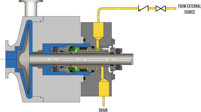
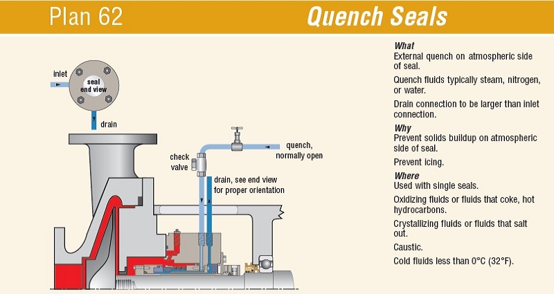
API Plan 62 delivers an external quench fluid to the atmospheric side of the seal. A typical application in a refinery is the prevention of coking on seal faces in hot hydrocarbon service by employing a steam quench. Nitrogen or clean water may also be used to quench or cool and clean the atmospheric side of the seal.
See page 77 of the Mechanical Seal Support Systems Application Guide for additional details and ordering information. Contact your authorized Swagelok sales and service center for information on optional components.

The mechanical seal is the most likely part of the pump to fail. Approximately 70% of the pumps removed from service for maintenance are victims of mechanical seal failure. Mechanical seal parts are highly engineered with very close tolerances and any upset in the pump or associated system can cause seal failure, including:
Mechanical seals are based on positioning two very flat and smooth discs called seal faces, one rotating on the shaft and one stationary in the pump, against each other. The discs are flat and smooth enough to ALMOST prevent the pumped fluid from leaking out between them. However, the faces do rely on a very thin film of fluid between the faces to lubricate that rubbing fit. Without this film of fluid, the seals will overheat and fail. Lack of lubrication is the PRIMARY cause of seal failure. If the fluid is very hot, it can flash to a vapor as the fluid moves across the faces, again resulting in lack of lubrication. Note that gas seals use a gas film between the faces to minimize face contact and heat buildup.
Seal flush plans are intended to keep the area around the seal in the most seal friendly environment practical, usually meaning clean and cool. Dual seal plans also provide backup and leak detection for safety.
Note that seal flush plans use pressure differences at the pump to drive the flush fluids. The pump suction is low pressure, the seal chamber is a medium pressure, and the pump discharge is at high pressure.
As the seal faces faces rub together (with their thin film of lubricating fluid), they generate heat. The heat can build up in the seal chamber and push the fluid towards its boiling point, resulting in premature flashing, lack of lubrication, and failure. This first set of seal plans is intended to create circulation through the seal chamber to dissipate the heat out of the seal chamber and back into the pumped fluid.
Flush fluid flows from high pressure at pump discharge to the medium pressure seal chamber and back into the main flow to remove heat from seal chamber
Can be used to increase seal chamber pressure. Increased chamber pressure may be required to keep chamber fluid from flashing to vapor or to provide enough pressure to push the fluid between the faces for lubrication. (Seal chamber must be 5 psi minimum above external atmospheric pressure).
These seal plans are intended to provide the seal with the friendliest environment possible by cooling and/or cleaning the fluid in the seal chamber. The throat that separates the seal chamber from the main pumped fluid can be further restricted by adding a close clearance bushing in the bottom of the seal chamber, better isolating the cool, clean seal chamber fluid from the hot, abrasive fluid in the pump.
Rather than a Plan 21 single pass system, a Plan 23 is a multi-pass system. Fluid comes FROM THE SEAL CHAMBER instead of the pump discharge, is cooled, and directed back to the seal chamber.
Fluid is driven out of the chamber and through the cooler by “pumping ring” or other “pumping feature” built into the seal. These features provide very little differential pressure. Connecting tubing must have long, sweeping bends, well vented high points, and low point blowouts to ensure fluid flows.
Quench piping does NOT change conditions inside the seal chamber, at the wet side of the seal faces. Rather, it affects or monitors the environment on the ATMOSHPERIC side of the seal faces.
Pumps that leak when they are filled, even before they are started, often have a flush line intended for a Plan 11 or 13 connected to the QUENCH port, leading to the atmospheric side of the seal. There should be a “Q” or the work “QUENCH” stamped in the gland at this port.
For flush plans Plan 65A, 65B, 66A, and 66B, facility owners may want to know if their seals are leaking excessively without going to the expense of dual seals. These seal plans direct excessive leakage on the outside of the seal to an alarm instrument. Remember that seals leak a little bit. They need to in order to lubricate the faces and function correctly. The plans below handle the nuisance leakage in different ways.
Used in salting services like sodium hydroxide. The leakage across the seal faces will turn to salt when it reaches atmosphere. The salt crystals can wear the faces or build up in the seal, preventing the movement necessary to keep the seal faces in contact. The salt on the outboard of the seal can be washed away with a water quench through the quench and drain ports. Usually a close clearance bushing is installed at the extreme outboard end to the seal assembly to help keep the quench fluid moving from the quench to the drain port (or vice versa) and not just run out along the shaft. Also used for slurry services.
Grease can be introduced into the quench port. This external grease can provide temporary lubrication to the seal in case the pump sees large air or vapor pockets which would normally rob the seal faces of the required lubricating fluid film.
Quench can also be gas. In hot hydrocarbon services, the fluid will turn to solid coke when it reaches the atmospheric side of the seal. The fluid would remain a liquid if the area outside the seal faces is robbed of oxygen with a flood of nitrogen or steam.
An alarm does NOT necessarily mean a failed seal. The collection vessel might be full from years of nuisance leakage. Try emptying the vessel and observing how fast the vessel fills.
Two throttle bushings are used to ensure that the vapor (or fluid) leakage is limited along the shaft and out of the drain. A pressure switch picks up a rise on pressure above nuisance levels on the outboard side of the seal.
Dual seals provide a backup seal in case the primary seal fails. They prevent hazardous fluids from leaking to the surrounding area, desirable for both environmental protection and the safety of nearby personnel. Dual seals also capture and control any leakage of pumpage across the primary seal. The backup seal is kept lubricated by introducing a buffer/barrier fluid (often a mineral or synthetic oil, a water/glycol mix, or diesel) into the space between the primary (inboard) and secondary (outboard or backup) seals. The buffer/barrier fluid is contained in a tank (5 gallons is most common) adjacent to the pump. Instrumentation on the tank indicates what is happening with the seals.
Remember that a lubricating fluid film will flow from high pressure to low pressure. If the pump seal chamber pressure is higher than the pressure on the other side of the seal, the pumpage will be the lubricating film. If the pump’s seal chamber pressure is lower than the external pressure, the external atmosphere will migrate into the pump. Pumps under vacuum cannot use an ordinary single seal, since air from the atmosphere would be drawn between the faces, causing them to run dry and fail. Using a dual seal allows a fluid to be present at the outside of the seal. In a pump under vacuum, the buffer fluid would be pulled into the pump between the seal faces, keeping the inboard seal well lubricated.
If the pump seal chamber pressure is higher than the BUFFER fluid between the primary and backup seal faces, then the pumped fluid will flow from the high seal chamber pressure into the low pressure buffer fluid. This is called a DUAL UNPRESSURIZEDseal (formerly called a tandem seal), and the fluid is called a BUFFER fluid.
If the pump seal chamber pressure is lower than the BARRIER fluid between the primary and backup seal faces, then the barrier fluid will flow across the primary seal from the space between the primary and backup seals into the pump. This is called a DUAL PRESSURIZEDseal (formerly called a double seal), and the fluid is called a BARRIER fluid.
Buffer fluid circulates from the buffer fluid reservoir, through the space between the primary and backup seal, and back to the reservoir. Fluid is circulated by a weak pumping action built into the seal.
It the fluid flashes to vapor at low pressure, the vapor is piped to a flare or vapor recovery system, through an orifice at the top of the tank. If the primary seal is allowing too much leakage, the vapor will build pressure in the reservoir against the orifice and a pressure instrument can alert the operator.
If the fluid remains as a liquid under low pressure, any leakage will cause the fluid level in the buffer tank to rise, where a high level alarm can be tripped. Just because the high level alarm is tripped does not mean that the primary seal is failing; it is the rate of leakage filling the tank which matters. The high level may have been reached after collecting years of nuisance leakage. Often, an oil change to the original level is all that is required. Be sure the fluid is disposed of properly.
Seal face friction or hot pumpage can add heat to the buffer fluid. A cooling water coil is often installed in the reservoir to cool the buffer fluid.
Dual pressurized system (seal barrier fluid is at a higher pressure than the pump seal chamber). Pressurized systems are used to ensure that very dangerous fluids remain in the pump. The difference between 53A, 53B, and 53C is the method of pressurizing the barrier fluid. Pressure in the barrier fluid should be at least 10 psi over the pressure in the pump seal chamber.
Barrier fluid circulates from the barrier fluid reservoir, through the space between the primary and backup seal, and back to the reservoir. Fluid is circulated by a weak pumping action built into the seal.
A low level alarm in the reservoir alerts the operator that a seal may be failing, allowing the barrier fluid to enter the pump through the primary seal or the atmosphere through the backup seal.
Seal faces can be designed to maintain a gas film between them rather than a fluid film. These piping plans are intended to work with theses gas film (dry running) seals. Plan 72 and 74 bring the buffer or barrier gas into the seal; plans 75 and 76 are for the gas exiting the seal.
Secondary seal is ordinarily running with a gas film between the faces. When the primary seal fails, the pumped fluid will fill the space between the primary and backup seal. The backup seal is now working as a liquid seal rather than a gas seal and is designed to run for about 8 hours, allowing the operators time for an orderly pump shutdown.
Plan 72 buffer gas flow keeps the gas in the seal from becoming concentrated from nuisance leakage over time so that any leakage from the gas backup seal is mostly inert flush gas and not toxic pump vapors.

After more than five years of planning, the American Petroleum Institute (API) is preparing to release the 4th edition of API Standard 682 (ISO 21049:2011). The API 682 standard, which dates back to 1994 and is formally known as Shaft Sealing Systems for Centrifugal and Rotary Pumps, offers specifications and best practices for mechanical seals and systems to pump end users.
The standard’s latest edition began to take shape in 2006, when API formed a 4th edition task force to respond to end users’ questions and comments about previous editions. The task force soon realized that major changes, including reorganization and editing, would be necessary. While addressing every aspect of the resulting 4th edition (which is more than 250 pages long) would be impossible, this article summarizes the standard’s main points.
Those who use API 682 should understand the standard’s scope and remember that the standard does not include specifications for equipment outside that scope, such as engineered seals or mixers. Another important but often misunderstood point is that API 682’s figures are illustrative and not normative in their entirety.
For example, one of API 682’s figures shows a fixed throttle bushing combined with a rotating Type A seal, but seal manufacturers do not always have to combine these two components. The standard provides normative details in clauses and tables to help purchasers distinguish between requirements and suggestions.
The 4th edition continues to divide seals into three categories, three types and three arrangements. For all practical purposes, seal manufacturers can combine a seal’s component parts into nearly any orientation or configuration. Each orientation and configuration has advantages and disadvantages with respect to certain applications, performance and system disturbances.
Before the 4th edition, API 682 did not specify a minimum clearance between the inside diameter of a stationary seal part and the outside diameter of a rotating seal part. The 4th edition specifies this minimum clearance—typically the clearance between the sleeve and the mating ring. The specified clearances are representative of standard clearances that end users have used for decades. End users should not consider seal components to be “shaft catchers” to restrict shaft movement. The minimum clearance specified in API 682 also applies only to equipment within the standard’s scope. Equipment outside that scope, such as non-cartridge seals, older pumps, non-API 610 pumps and certain severe services, might benefit from larger clearances.
The new standard also updates the default bushings for the gland plate for the three seal categories. Fixed throttle bushings are now the default for Category 1 only, while floating bushings are the default for Categories 2 and 3.
While the 4th edition features the recommended seal selection procedure from the standard’s first three editions, it adds an alternative selection method in Annex A. Proposed by task force member Michael Goodrich, this alternative method recommends using material data sheet information to select a sealing arrangement.
Plan 65 is now subdivided into 65A and 65B. End users can use Plan 65A to detect an excessive leakage flow rate and Plan 65B to detect a certain amount of cumulative leakage.
Plans 66A and 66B are new to the standard, although end users have used them previously in pipeline applications. These plans detect and restrict excessive leakage rates in case of an Arrangement 1 seal failure.
The 4th edition now requires Plan 52, 53A, 53B and 53C systems to have a sufficient working volume of buffer or barrier fluid for at least 28 days of operation without refilling. As a point of reference, the default reservoir for Plans 52 and 53A has a three-gallon capacity, or pot, for pump shafts smaller than 2.5 inches and a five-gallon pot for larger shaft sizes. Plan 53C must have the same working volume of fluid as Plan 53A. For Plan 53B, the default bladder and accumulator sizes are five gallons and nine gallons, respectively. The design of Plan 53B systems can be complex, especially when ambient temperatures vary widely, and purchasers should become familiar with the calculations and procedures in the 4th edition’s Annex F tutorial. The new edition also discusses the option of adding a pressure gauge and isolation valve to check the accumulator or bladder’s integrity in a Plan 53B system.
The 4th edition has revised the data sheets in Annex C extensively to make them the same for all seal categories. Only two data sheets are included in the 4th edition—one in metric units and one in U.S. customary units. The new edition also folds Annex J into Annex E.
Previous editions of API 682 required metal plugs and anaerobic sealants when shipping new or repaired cartridges. After much debate, the task force decided that threaded connection points should be protected with plastic plugs for shipment. These plastic plugs should be red and have center tabs that operators can pull easily to distinguish the plugs from metal plugs. Shippers should also attach yellow warning tags to the plugs to indicate that end users need to remove the plugs before operation.
Although tutorial notes are scattered throughout API 682, this edition expands the tutorial section, Annex F, from seven pages to 42 pages. The expanded annex includes illustrative calculations. In particular, users interested in systems such as Plan 53B will find Annex F to be useful.
The 4th edition of API 682 is the product of more than 20 years of discussion, debate, usage and peer review. It includes a strong set of defaults and is by far the best and most logical starting point for mechanical seal and systems use. Equipment operators should take the time to familiarize themselves with API 682 to get the most out of this comprehensive standard.

Most pump experts would agree that mechanical seals on a rotating industrial pump are one of the most important components regarding pump performance and longevity. Rotating industrial pumps are designed with double mechanical seals located at the shaft that connects the impeller or rotor to the motor. As the motor applies force to the shaft, the shaft spins, which in turn, spins the impeller or rotor which is connected to the far end of the shaft. This spinning action of the shaft and impeller or rotor is what produces the flow rate of the pump. The double mechanical seals are a wear component that must be replaced periodically or the pump will not perform as expected, or even worse if these seals fail it can cause a catastrophic failure resulting in substantial cost to repair or replace the pump.
Most often, failure of the mechanical seals is due to being exposed to excessive heat that is generated by the turning or spinning action of the shaft. This build-up of excessive heat at this area of the pump is also the reason why many rotating industrial pumps cannot operate in a run-dry condition. When a pump runs dry without fluid circulating through the wetted path, a greater amount of heat is generated at the mechanical seals. Subjecting the mechanical seals to a greater amount of heat than what they can withstand causes premature failure of the seals.
A solution to avoiding the overheating of mechanical seals in a rotating industrial pump is Seal Support Systems. Seal Support Systems are designed to flush the mechanical seal area of the pump with fluid. This flushing action reduces the build-up of heat, increases the longevity of the pump, and avoids premature failure of the mechanical seals due to overheating.
There are a number of different Seal Support System designs available on rotating industrial pumps. Some of the different designs available meet the American Petroleum Institute (API) standards for pumps that are to be used in the Oil and Gas industry. A couple of the most prevalent API standards for Seal Support Systems API Plan 53A and API Plan 62. Both of these systems are designed differently; The API Plan 53A Seal Support System is designed with a closed-loop system, and API Plan 62 Seal Support System is designed with an open system where the flushing fluid is immediately discarded from the pump directly after the flushing fluid flows through the mechanical seal area and expels the heat.
Both of these seal support systems are very effective at reducing heat build-up that can destroy mechanical seals. Although both of the types of seal support systems reduce heat build-up, some environments require the use of a closed-loop seal support system to avoid the flushing fluid from exiting the pump and contaminating the area that the pump is operating.

API Standard 682, titled "Pumps - Shaft Sealing Systems for Centrifugal and Rotary Pumps," is the American Petroleum Institute (API) standard for end-face mechanical seals.centrifugal pumps. It is based on the combined knowledge and experience of seal manufacturers, engineering companies, and end users. API 682 is primarily intended for use in the petroleum, natural gas and chemical industries, but is often referenced for other types of equipment and industries.
By the late 1980s, mechanical seals had been accepted as the preferred method for sealing rotating pumps for many years. However, mechanical seal standards were generally buried in other standards such as DIN 24960, ANSI B73, and API 610. All of these standards were primarily pump standards and any references to seals were directed at how mechanical seals would interact with pumps.
API 610 is the API standard about centrifugal pumps and is primarily intended for use in the petroleum, natural gas and chemical industries. Although the 1st through 7th Editions of API 610 included specifications for mechanical seals, beginning with the 8th Edition, API 610 defers to API 682 for seal specifications.
In the late 1980s a group of refinery equipment engineers and managers began to compare sealing solutions in refinery applications. This group, led by V. R. Dodd of Chevron, came up with a general plan and the American Petroleum Institute (API) agreed to establish a standard for mechanical seals: API 682. A Task Force was formed in 1990 and the first meeting was held in January 1991. This Task Force was composed of fourteen members from various refineries, seal and pump manufacturers. API 682, First Edition, was published in October 1994.
One interesting aspect of API 682 is that it includes a strong set of defaults. That is, unless the user indicates otherwise, API 682 makes default choices for specifics such as:
Some statements within API 682 are normative, that is, required, whereas others are informative, that is, descriptive but not required. In particular, many of the illustrations are informative. This distinction has not always been apparent to the reader.
The first edition of API 682 was entirely new although parts of it were extracted from the pump standard API 610 and existing API standard paragraphs.
Although this mission statement no longer appears in the standard, it remains the basic principle driving the work of the API 682 Task Force and its relevance remains the same for the 4th Edition as it did for the 1st.
In addition to providing requirements for mechanical seals, the 1st Edition of API 682 also provided a guide on how to select the correct seal for a number of common refinery applications. In order to provide this seal selection guide, it was necessary to categorize applications into a number of services:
Prior to API 682, 1st Edition, multiple seals were designated as being either “tandem” or “double” seals; however, advances in seal design had rendered these classic terms obsolete. As a result, there was some confusion on how multiple seals were designated. The task force decided to use a more descriptive designation and chose to define dual seal arrangements. A dual seal would be two sets of sealing faces used in the same seal chamber. The fluid between these two sets of sealing faces could be either pressurized or unpressurized. Three standard arrangements were defined:
After having defined the services, seal types, and seal arrangements, a series of flowcharts were created to help in selecting a seal type, special materials or design requirements, and supporting piping plans.
API 682 seals were to have a high probability of three years of reliable service. In order to prove this, seal performance testing on process fluids under representative pressures and temperatures was required. These performance tests are called “Qualification Tests”.
The general idea of the qualification test was to prove that the design was sound. The goal of the qualification test was to simulate a long-term steady state run followed by a process upset. The simulated process upset consisted of pressure changes, temperature changes and included loss of flush. The results of these tests were made available to the purchaser for evaluation. There was no acceptance criteria presented in API 682 1st Edition.
In addition to the qualification test of the design, every API 682 seal, whether new or repaired, is to be pressure tested with air before being shipped to the end user.
One of the major criticisms of API 682 1st Edition was that all the seals were “heavy duty” and therefore expensive with no alternatives for easy services. To some degree, this was intentional and was done in order to reduce inventory, promote familiarity with a limited number of seal types and to increase reliability. Another criticism of API 682 1st Edition was that it considered only API 610 pumps and only refinery applications. The chemical and petrochemical industries routinely use ASME pumps in addition to API 610 pumps. Broadening the scope of pumps covered by API 682 would allow standardized seals to be applied in a greater number of industries.
In 2nd Edition, the organization of API 682 was changed to conform to ISO standards: This reorganization means that there is no simple cross reference guide between 1st edition and 2nd edition paragraph numbers.
The 2nd Edition introduced the concept of seal categories. A seal category describes the type of pump into which the seal will be installed, the operating window, the design features, and the testing and documentation requirements. There are three categories designated as Category 1, 2, or 3.
Category 1 seals are intended for non-API-610 pumps. This category is applicable for temperatures between –40°F and 500°F (-40°C and 260°C) and pressures to 315 PSI (22 bar).
Category 2 seal are intended for API-610 This category is applicable for temperatures between –40°F and 750°F (-40°C and 400°C) and pressures to 615 PSI (42 bar).
Category 3 seals are essentially the original seals of 1st Edition and are also intended for API-610 pumps. Category 3 seals are intended for the most demanding applications. This category is applicable for temperatures between –40°F and 750°F (-40°C and 400°C) and pressures to 615 PSI (42 bar). Design features include a distributed flush and floating throttle bushing for single seals. Additional documentation must be also provided.
Containment seals are the outer seal of Arrangement 2. In the 2nd Edition, containment seals can be used with a liquid buffer fluid, a gas buffer fluid or without a buffer fluid. In the case of a dry running containment seal, the containment seal will be exposed primarily to buffer gas or vaporized process fluid. Such containment seals must therefore be designed for continuous dry running while meeting the reliability goals of the standard. Dry running containment seals may be either contacting or non-contacting.
Non-contacting inner seals are also introduced for Arrangement 2. One of the primary targets for non-contacting inner seals is in flashing hydrocarbon services. In some of these services, it is impossible to obtain adequate vapor margins to prevent flashing of the fluid in the seal chamber. This seal will be used with a dry running containment seal and the leakage past the inner seal will be piped to a vapor recovery system.
The other new seal type introduced in 2nd Edition was the dry running gas seal used in Arrangement 3. This seal is designed to run on a gas barrier fluid such as nitrogen.
Several new piping plans were introduced in the 2nd Edition. These included additional options for dual pressurized liquid seals as well as new piping plans to support containment seals and dual pressurized gas seals.
One of the strengths of the 1st Edition was to provide qualification tests in which seal vendors would be required to prove the suitability of their seals for a given service. The 2nd Edition expanded on these requirements by adding new tests for containment seals and dual gas seals as well as defining acceptance criteria for all tests.
For all practical purposes, API 682 3rd Edition is the same as 2nd Edition. The completed 2nd Edition was submitted to the ISO Organization for approval as their ISO 21049. At the time, API and ISO had an agreement to jointly issue standards. The ISO Organization made slight editorial changes to 2nd Edition, including correcting typographical errors and unit conversions. Therefore, API had to re-issue a corrected 2nd edition but choose to label it as 3rd edition. API 682 3rd Edition was published in September 2004.
API and ISO no longer have the agreement to jointly issue standards. The 2004 issue of ISO 21049 is the only issue and plans to update it are unknown.
Seal Configuration refers to the orientation of the seal components in an assembly. In previous editions, orientations were defined as face-to-back, back-to-back, and face-to-face and these terms are carried over into the 4th Edition. In 4th Edition, any orientation (face to back, back to back, face to face) can be used in a dual seal provided that the design features are appropriate to the functionality of that particular arrangement.
Fourth Edition added additional specifications for clearances, placed these requirements in the form of tables and noted that seal components are not to be considered as “shaft catchers” to restrict shaft movement. The minimum clearances specified apply only to equipment within the scope of the standard. Equipment outside that scope, such as non-cartridge seals, older pumps, non-API 610 pumps and certain severe services, might benefit from larger clearances.
Before API 682, API 610 (the pump standard) used a simple seal code to specify seals. API 682 attempted to use a more comprehensive seal code; however, that code changed with every edition of API 682. The 4th Edition code, described in Annex D, is probably the best to date and includes some concepts and codes from the historical API 610 seal code.
Annex G provides illustrations and a short tutorial about each piping plan. As has been the case for every edition, changes were made to the standard piping plans. In particular, the piping plans now default to using transmitters with local indicators as part of the instrumentation.
API standards are reviewed every five years and re-issued every ten years. A new Taskforce for API 682 was formed in 2017 and preparations for 5th Edition are underway.
Buck, G. S., Huebner, M. B, Thorp, J. M., and Fernandez, C. L. “Advances in Mechanical Sealing – An Introduction to API-682 Second Edition”, Texas A&M Turbomachinery Symposium, 2003.
API Standard 682, Second Edition, 2001, “Pumps – Shaft Sealing Systems for Centrifugal and Rotary Pumps,” American Petroleum Institute, Washington, D.C.
API Standard 682, Third Edition, 2004, “Pumps – Shaft Sealing Systems for Centrifugal and Rotary Pumps,” American Petroleum Institute, Washington, D.C.
API Standard 682, Fourth Edition, 2014, “Pumps – Shaft Sealing Systems for Centrifugal and Rotary Pumps,” American Petroleum Institute, Washington, D.C.
In LIDERING we have an extensive range of mechanical seals for all types of pumps: from seals for domestic pumps to seals for process pumps, specific in complex applications in the chemical and petrochemical industry. In addition, we offer a wide range of spare parts compatible with the originals of the main manufacturers of pumps (RMS). Our catalog also includes cartridge seals for more demanding industrial processes, and our extensive range of products is ever-growing in order to adapt to the requirements of our customers.

Plan 62 is not a pressurised seal flush plan, which is what you need here. Suggest one of the plan 53 arrangements. And the seal may need to be good for temperatures high enough to keep the surrounding sulphur molten. Whether it will be plan 53A, B or C is subject to disclosue of more information and the seal / pump vendor may also be able to assist. The barrier fluid may need to be kept above the melting temperature of the sulphur. Believe the melting points for sulphur are different for the 3allotropes (alpha phase, beta phase and gamma phase)-which one do you use? RE: Molten Sulphur Pump: Premature Mechanical Seal Failure
The melting point of our sulphur is 116 deg. C. We are not having any problems with the secondary seal of plan 62; however, I will take heed of your suggestion. Furthermore, I am doubting the suitability of plan 01. Is it much better to install plan 02?
Plan 53 doesnt have the process fluid as primary seal flush, since these are double seals operating with a pressurised barrier fluid, so the risk of molten sulphur cooling down on the route to cool the seal surfaces is avoided. So yes, may need to get avoid this plan 01 for this molten sulphur application.
The risk with plan 53 here is potential overcooling of the recirculating barrier fluid which may affect the molten sulphur around the seal cartridge area - this is applicable to both shutdown and normal operating modes. By the way, how do you warm up the pump casing during startup, especially around the shaft seal area? RE: Molten Sulphur Pump: Premature Mechanical Seal Failure
I think the use of Plan 53B may cause complication due to the cooling configuration not unless we maintain the barrier fluid at an average temperature higher than the melting temperature. We will as the manufacturer for seals that can operate on that range. RE: Molten Sulphur Pump: Premature Mechanical Seal Failure
I would add a steam jacket to the seal gland. I would convert from Plan 1 to Plan 2, as you suggested. Most of our sulfur pumps are vertical pit pumps with no mechanical seal. But, the one pair of sulfur pumps we have that do use mechanical seals use the arrangement I have proposed. The seal reliability is not as good as plant average. But, we have been getting acceptable seal life using this system.
Sulfur has a very narrow temperature range when it has suitable properties for lubrication of seal faces. Either too hot or too cold and the performance is poor. A good system of steam jackets with the steam conditions held a few degrees above the ideal temperature is the best way to achieve acceptable seal life. I am not sure how you would maintain this temperature using a Plan 53.
JJPellin has it right. Unless it"s a safety regulation at your site, I almost always recommend utilizing a single seal with a plan 02/62. Dual seal plans (including those for gas seals) in hot applications such as molten sulfur tend to act as heat sinks for the mechanical seal, even at ambient temperatures. Add a steam jacket to the gland and always follow proper steam piping techniques.
1) There is no temperature interlock on the system. This allows operations to just switch the system on even though it may not be at temperature. Stuff breaks as the pump and seal attempt to rotate in solidified sulfur.
2) The interlock for the system is in an inappropriate location. My best recommendation for the location of a thermocouple/temperature probe would be in the seal chamber. If the seal chamber is at temperature, then the critical areas within the pump are likely close to temperature. This is your best shot at avoiding heavy damage during start-up. RE: Molten Sulphur Pump: Premature Mechanical Seal Failure
We will be inquiring our manufacturer if they can provide us with the steam jacketed seal gland. Apperently our mechnical seal is, in fact, a single seal configuration. I am wrong on my previous statement of it being dual. Appologies.
With regards to the interlock system, our pumps do not have any thermocouples to monitor seal chamber temperature. What we maintain, however, is the steam inlet pressure for the pump jacket.
Yes, the only way for a plan 53 to work would be if the barrier fluid were to be kept at well above 116degC. But if the plan 02 is the better way to go, okay.
Viking make pumps with electric casing heaters and temperature sensors fitted into the casing, and these include sensors picking up seal cartridge area temp also. Pump casing TSLL interlock for pump start sequence is a must as suggested. RE: Molten Sulphur Pump: Premature Mechanical Seal Failure
To answer your question, yes, mechanical seals can be designed to include additional flush ports (NPT) so that a temperature indicator can be installed. However, I have found that you get more bang for your buck if your pump allows for an NPT connection into the stuffing box (often referred to as a cage-ring tap). If you are utilizing a standard ANSI pump for this application then there is a good chance the stuffing box design already incorporates this tap (or can be drilled). On most pump models, having a temperature indicator in the stuffing box allows you to achieve a relatively accurate reading of the bulk temperature behind the pump impeller and at the mechanical seal faces. At a minimum, these are the two areas we are most concerned about the sulfur being liquid before we turn the pump on in order to prevent failures.
As another poster mentioned, electrical tracing or the use of blankets to heat the pump is an option. For smaller pumps, often this method is very effective. For larger pumps or other designs with bulky casings, it can be difficult to dump enough heat onto the surface of the pump in order to bring the sulfur into the appropriate temperature window. This is especially true in locations where the winters can become harsh. RE: Molten Sulphur Pump: Premature Mechanical Seal Failure
Mechanical seals are components that keep the pumped fluid (or “pumpage”) confined to the pump casing. These seals are installed at the location where the shaft enters or leaves the casing and their purpose is to prevent leakage. There are many hundreds of styles and sizes and configurations of seals. All use the underlying principles of stationary and rotating face combinations (Fig. 1). Some are simple and inexpensive; others are complex and deserve special attention (Ref. 1).
Conventional mechanical seals often apply spring pressure or some other closing force to the face of the rotary unit in Figure 1. However, many mechanical seals are designed with a single coil spring, others with several small coil springs, still others with pleated bellows applying a closing force to the stationary seal part. They are called rotating mechanical seals if, as configured in Figure 1, the spring-loaded face is part of the rotary unit and is clamped to the shaft. It wobbles, so to speak.
We use the term stationary seal whenever a spring-loaded closing force is applied to the non-rotating (stationary) seal unit. Stationary seals are advantageous when there is known shaft deflection and in shaft systems that operate at high peripheral velocity. As the shaft deflects under load, a conventional seal will have its springs moving at all times. Not so with stationary seals. As the shaft deflects, the spring or springs in a stationary seal will compress or elongate only to accommodate the new shaft inclination/deflection. In other words, the face will always be at a right angle (90 degrees) to the shaft.
In all cases and regardless of seal type, designs that place the springs away from the process fluid are generally preferred over designs that allow process fluid to contact the springs. Also, all seal assemblies need some kind of vent provision, be it a port “A” or a simple vent passage “B” (Figure 1). In some instances, not providing an appropriate vent passage will doom the seal.
Since about 1950, mechanical seals have almost totally replaced the more maintenance-intensive compression packing previously used in process pumps (Figure 2 above). But suppose you are presently in the process of converting to mechanical seals. In that case and until conversion work is completed, use this installation and servicing sequence:
Working with a competent seal manufacturer avoids mistakes and adds value (Ref. 2). Reliability-focused users never view mechanical seals as a cheap standard commodity. These users select only experienced seal manufacturers and cultivate relationships based on mutual trust. Long-term customer service and consistent application of thorough engineering products and best available work procedures benefit all parties and are of much greater importance than short-term returns obtained from initially paying a low price. A single failure incident often causes price-related gains to vanish in a flash—both literally and figuratively. Optimized seal flush piping arrangements are needed to create the most appropriate seal environment.
1) “Flush” — Clean, cool liquid is injected into the seal chamber to improve the operating environment. A second, smaller port is provided and normally oriented downward. It often serves as a leakage observation or vent opening.
2) “Barrier or Buffer” used with dual seals — A secondary fluid is fed to the space between two sets of mechanical seals to prevent ambient air from contacting the pumped fluid, to improve seal cooling, and/or to enhance safety.
It is worth mentioning that not all mechanical seals require special external flush arrangements. Still, for long and trouble-free life the mating faces shown in Figure 1 must somehow be separated and/or cooled. Cooling prevents the liquid film between mating seal faces from vaporizing. Not all seals require cooling and quite often the pumpage itself can serve as a suitable separating and cooling fluid between the seal faces.
However, the very small gap (typically 0.0001 to 0.0003 inches) between faces can be taken up by either liquid or gas. Different face configurations and API (American Petroleum Institute) flush plans (flush schematics) accomplish that; these plans vary because they must accommodate different fluid parameters, conditions, and properties. All flush plans are described in vendor literature and industry specifications such as API-682 and ISO 21049. A few of them are shown in Figures 3 through 8; the ones we have selected here use API plan numbers and are representative of the many different piping or flush plans available (Ref. 3).
Note that the flush piping in most plans enters or exits at the top of the seal chamber which then also allows vapors to be vented. In the few instances where no such piped venting possibility exists, the pump user may have to drill a 0.125 inch (3 mm) diameter passageway (labeled “B” in Figure 1) at an angle of 15 to 45 degrees from the top corner of the seal chamber into the fluid space directly behind the impeller.
In pre-existing pumps certain upgrades or conversion to another (more modern) flush plan configuration are often advantageous. Where energy conservation issues and operating cost savings are deemed important the newer seal configurations must be considered.
Recirculation of a product side stream (Plan 11, Figure 3) is common. The side stream should have a pressure of approximately 25 psi (173 kPa) higher than the pressure directly behind the pump impeller.
A heat exchanger (Figure 4) adds to the cost of an installation, but may be required in some services. Modern mechanical seals often include an internal pumping device—an important option that will be further explained later in Figure 12.
Some applications favor the flush plan shown in Fig. 5 although, again, its ultimate suitability for a given application or service must be assessed. The liquid injected into the seal cavity will migrate through the throat bushing and into the pumpage. This dilutes the process fluid and the injected fluid will later have to be removed by evaporation. Because evaporative processes require considerable heat the overall energy efficiency of the plant is inadvertently reduced simply because of a particular seal plan selection.
Fig. 6: API Plan 53A—Pressurized barrier fluid circulation in outboard seal of a dual seal configuration. A pumping ring maintains circulation while running; thermosiphon action is in effect at standstill
Dual seals utilize a barrier or buffer fluid to create a desirable seal environment, Fig. 6. The cost of the seal auxiliaries shown here is clearly a factor and each application merits its own review. Connection to an external nitrogen source requires safeguards against the inadvertent backflow of barrier fluid into the external source of nitrogen. The possibility of nitrogen dissolving in the barrier fluid must be considered as well. In other words, seal selection requires considerable study and experience.
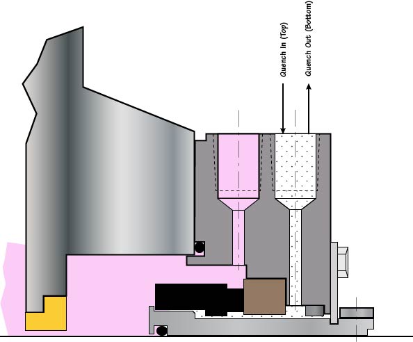
Both Figures 7 and 8 are variations on our “go with advanced technology” theme and highlight why it is so important to have good cooperation between seal manufacturer and seal user-operator. Figure 8 (API Plan 62) is schematically shown again in Figure 9; it is important to note that many of these seals and flush plans have been converted to the far more effective water management approach shown in Figure 10.
Fig. 7: API Plan 53C—pressurized and cooled barrier fluid circulation in outboard seal of a dual seal configuration. A pumping ring (see later, Fig. 12) maintains circulation while running. The pressure is maintained and fluctuations are compensated in the seal circuit by a piston-type accumulator, upper right.
Fig. 8: API Plan 62—an external fluid stream is brought to the atmospheric side of the seal faces using quench and drain connections (This is a very inefficient use of water)
Fig. 10: Four water management systems connect to the seal glands of four separate pumps in this sample illustration. There is no drain and no water is wasted
The many properties of fluids contacting the seal faces govern seal selection, but other considerations should be weighed as well. Long-term reliability and savings in utilities should be given high priority. Conversely, low initial seal cost is rarely (if ever) a good indicator of the true value of mechanical seals and seal support systems (Ref. 3).
Fig. 11: Plan 23 cross-section of a seal cavity with a bi-directional (tapered) pumping device. The flush product is pumpage that passed through the throat bushing on the left. After being cooled in a heat exchanger (upper right), this product re-enters the seal region in the vicinity of the seal faces. A bi-directional tapered pumping device (see Figure 12) promotes relatively high flow rates and thus cooler face temperatures.
Historically, Plan 23 has not received wide acceptance due to the obvious complications of applying old-style seal circulating devices or pumping rings. Utilization of modern computer-controlled manufacturing methods has helped implementing superior sealing technology.
Compact Plan 23 cartridge seals (Figure 11) are easily applied to both new and old pumps. These seals incorporate wide-clearance bi-directional tapered pumping devices that are far less likely to make contact with seal-internal stationary parts than older, close-clearance pumping ring configurations.
Seals are part of a pumping system and systems must be properly reviewed. This is demonstrated with API Plan 23, see Figure 11. The reviewer must first recognize that the seal assembly incorporates a throat bushing which will almost (but not fully) isolate the seal chamber from the pump’s case. The small volume of liquid in the seal chamber is circulated through a local cooler. API Plan 23 is used on hot applications and minimizes the load on the heat exchanger. It needs to cool only the heat generated by the seal faces and the heat that has migrated through the seal chamber casing. An effective pumping or circulating device (Figure 12) is at the very heart of Plan 23.
Many of the pumping rings found in mechanical seals are based on a straight vane or paddle-type configuration (Figure 13). Typical pump-around flow rates achieved with traditional pumping rings are quite low. They will function only in the plane where the ports and the straight vanes (paddles) are located. Tangential porting will be required and in many instances little or no liquid is induced to flow continually over the seal faces.
Pumping screws (Figure 14) are considerably more efficient; however, they must rely on a dimensionally close clearance gap between screw periphery and housing bore. This close gap can be a serious liability in situations where shaft deflection or concentricity issues exist. Designs with a close gap will not comply with the API 682 (2002) requirement of a minimum radial clearance of 1.5 mm (0.060”). But screw devices with large clearance gaps (Figure 14) have poor efficiency and can be as ineffective as the straight-vane pumping rings of Figure 13.
Fig. 14: Pumping screw found in some dual seals. To be effective these auger-type helical screws will require close clearances, but close clearances introduce risk factors
Some dual seals applied in industry are designed with radial clearances in the order of 0.010” and 0.020” (0.25 mm and 0.5 mm). This contradicts best-practice guidelines and technical logic because pumps operating away from BEP (“Best Efficiency Point”) and most single volute pumps are known to undergo a measure of shaft deflection.
Whenever the dual seal radial clearance is less than the throat bushing clearance in the pump, a close-clearance helical screw device will be the first to make contact. All these potential issues are avoided with open-clearance bi-directional tapered pumping rings (Refs. 2 and 3).
We chose here to summarize the seal topic by using a few schematic representations. In one particular API Flush Plan explained in Refs. 2 and 3, process fluid is diverted from the discharge of the pump, sent through a restriction orifice and a seal flush cooler, and then routed into the seal chamber. The seal flush cooler is removing heat from the process stream. If the production process demands a hot fluid, such heat removal will benefit only the seal. In that case, cooling the flush stream would reduce the overall process energy efficiency.

Pumping fluids at extreme temperatures presents many challenges to the shaft sealing system. It must ensure the pumped fluid is safely contained while providing longterm reliability. Many pump operators are familiar with hot pumping services, but cold services offer some unique challenges to achieving reliable shaft sealing solutions.
The pumps used to pump these cold fluids are often specialized designs. Low temperature hydrocarbons are commonly pumped with American Petroleum Institute (API) 610 (VS6) vertical multistage double casing pumps that feature a warming chamber, known as a cofferdam, that thermally isolates the shaft seal from the cold pumped fluid. This enables a greater range of shaft sealing solutions that can be used on these pumps using traditional sealing technology.
A cofferdam is a chamber between the pump discharge and the mechanical seal that is connected to the pump suction or the vessel the pump is drawing suction from. Ambient heat surrounding the pump together with energy from the shaft and bearings causes the liquid in this chamber to vaporize into a gas, which forms an insulating barrier between the seal and process fluid. Cofferdams can only be incorporated into vertical pump designs.
However, although vertical arrangements are common, various horizontal pumps can also be employed. In these types of pumps, the shaft seal is in direct contact with the cold pumped fluid, thus selection of the seal materials for low temperature operation becomes more critical.
For pump designs where the mechanical seal is immersed in the pumped fluid, vapor pressure margin in the seal chamber becomes critical. Where the vapor pressure margin is low, the heat energy from the mechanical seal faces can vaporize the fluid around the seal and in the seal interface, resulting in dry running of the seal. Seal chamber pressure can be increased through various flush piping plans to overcome this issue. However, when insufficient vapor pressure margin remains for the selected mechanical seal technology, a dual pressurized seal is recommended. A dual pressurized seal provides a stable barrier fluid to lubricate the seal faces, thereby negating the effect of vaporization of the pumped liquid at the seal faces.
API Plan 53B and 53C barrier systems are commonly selected for dual pressurized seals to provide a source of warm, clean and stable barrier fluid to the mechanical seal. When an API Plan 53C is selected, extra care should be taken to ensure the pressure amplifying piston seals are insulated from exposure to cold temperatures.
The availability of suitable barrier fluids becomes limited at low temperatures as the viscosity of many fluids becomes too high at the seal chamber operating temperatures.
When sufficient vapor pressure margin exists within the seal chamber, a dual unpressurized seal can be selected. These designs feature a dry sliding containment seal fitted with API Plan 76 or a combination of Plan 72 and 76. These seal arrangements have the advantage of removing the low temperature limitation of barrier fluid selection.
Icing caused by condensation of atmospheric humidity can create a problem for cold hydrocarbon services. Because condensing water expands as it freezes, it can interfere with the operation of the mechanical seal if it gets to the seal"s operating mechanism. Extra protection considerations should be applied to equipment exposed to atmospheric elements. An API Plan 62 using a dry nitrogen quench can protect the mechanical seal from these effects.
Hydrocarbons Low temperatures have significant implications to the choice of materials used in the seal construction. This is especially true for elastomers. Elastomers have a variety of minimum temperature limits, but none can survive dynamic operation at true cryogenic temperatures.
Engineered polymer seals are an option at temperatures below the limits of elastomers. Many of these designs will not function with pressure reversals applied to the sealing ring that may be required in the mechanical seal design when support system failures occur.
Elastomers can survive at significantly lower temperatures below their operational limits when the seals are not in operation (i.e. static), but they must be warmed up prior to operation. Commissioning of shaft seals containing elastomers must be completed carefully to ensure that the equipment is at the correct temperatures before startup. Blowdown, the rapid depressurization of a vessel/pipeline, is one situation that can create excessively low temperatures for the mechanical seal"s elastomers.
Thermal expansion (or in the case of cold services, contraction) is also a consideration. The cavities that elastomers or engineered polymer seals are installed in will change with decreasing temperatures as will the dimensions of sealing elements installed Image 2. Typical vaporizing liquid single noncartridge cryogenic seal in these cavities. Additionally, clearances between dissimilar materials, such as bushings, need reviewing. Mechanical seal manufacturers take these factors into consideration during the design of the mechanical seal.
Similar to pumping equipment for low temperature hydrocarbons, a mixture of vertical multistage and horizontal single stage pumps are used. These machines generally do not follow API pump design standards. However, since the temperatures are much colder than those at which hydrocarbons are pumped, cofferdams are not employed on these machines. A mixture of vertical and horizontal pumps are commonly employed at air liquefaction plants, but mobile trailer-truck unloading pumps are almost exclusively overhung single stage pumps, either with direct drive or speed increasing gearboxes.
Unlike hydrocarbons, emissions to atmosphere of atmospheric gases pose relatively minor hazards, thus shaft seal reliability takes precedence when selecting a shaft sealing system. There are two commonly employed shaft sealing technologies used in these pumps:
1 Single Mechanical Seals Single mechanical seals are the most common solution to pumps used in air liquefaction plant and mobile transportation unloading pumps. The major difference between the two is that the mobile unloading pumps tend to be smaller and often use noncartridge seals. Cartridge seals are commonly found in larger machinery at an air liquefaction plant.
Single mechanical seals use a metal bellows to provide elastomer-free axial flexibility. Seal face materials typically include filled TFE running against a tungsten carbide or hard-coated stainless-steel mating ring.
Similar to contacting wet seals, vaporizing liquid gas seals feature seal face topography that allows the controlled vaporization of the pumped atmospheric gas to produce a highly reliable seal that exhibits controlled low-level leakage rates.
This sealing configuration is most often found in vertical multistage pumps at air liquefaction plants. The design provides a controlled leakage by breaking down the sealed pressure over a series of tightly controlled bushing clearances. Leakage rates are higher than that of mechanical seals, however, these leakage rates are often considered acceptable in this industry.
Material Considerations for Liquefied Atmospheric Gases Sealing liquefied atmospheric gases presents some unique challenges to the selection of materials as the pumping equipment is often used interchangeably between the different atmospheric gases. Liquefied oxygen presents some special challenges since it is a very strong oxidizer and can cause certain materials to spontaneously combust. Additionally, any organic contaminates on the seal can also lead to spontaneous combustion.
Aluminum alloys should be avoided as they can become hazardous when their protective oxide film is stripped from the material such as when abrasion occurs. Lubricants used in the assembly and operation of the mechanical seal must be free of hydrocarbons and compatible for use in oxygen. Packaging of the seal should also be suitable to preserve the cleanliness of the seal prior to installation into the pumping equipment that is performed in a suitably clean environment.
We invite your suggestions for article topics as well as questions on sealing issues so we can better respond to the needs of the industry. Please direct your suggestions and questions to sealingsensequestions@fluidsealing.com.
Mark Savage is a product group manager at John Crane, responsible for the design, development and application of metal bellows seals for pumps, compressors and rotating machinery. He has worked in the sealing industry for 24 years with development of best practices for shaft seals and their support system. For more information, visit johncrane.com.


 8613371530291