
api plan 62 mechanical seal in stock

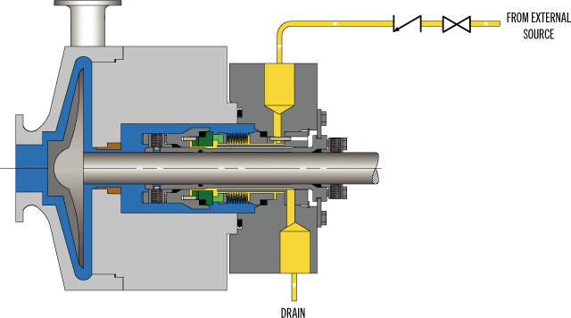
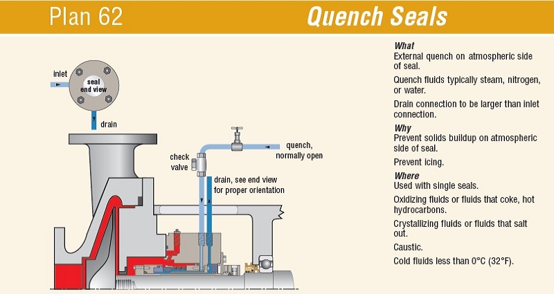
API Plan 62 delivers an external quench fluid to the atmospheric side of the seal. A typical application in a refinery is the prevention of coking on seal faces in hot hydrocarbon service by employing a steam quench. Nitrogen or clean water may also be used to quench or cool and clean the atmospheric side of the seal.
See page 77 of the Mechanical Seal Support Systems Application Guide for additional details and ordering information. Contact your authorized Swagelok sales and service center for information on optional components.
Advantages:Plan 62 is a low cost alternative to tandem seals. The quench prevents or retards product crystallization or coking. Quenches can also provide some cooling.
General:Typical applications include; steam quenches on hot services to retard coking; nitrogen quenches on cold or cryogenic service to prevent icing; or water quench to prevent crystallization or accumulation of product on the atmospheric side of the seal.

Plan 11: One of the most widely used flush plans nowadays. Plan 11 takes fluid from the pump discharge or from an intermediate stage and directs it to the seal chamber through a properly designed orifice (the side stream should have a slightly bigger pressure than the prevailing pressure directly behind the pump impeller) for cooling and lubrication of the seal faces. Similar to Plan 01, product contamination is avoided, whereas interconnecting piping is relatively easy to install.
Plan 12 Plan 12 is similar to Plan 11, with the exception that a strainer of filter is added to the flush line for protection of the seal surfaces. A differential pressure indicator or alarm is employed so as to warn the user that the strainer or filter has been clogged.
Plan 21: Plan 21 is a cooled version of Plan 11. A heat exchanger is installed between the pump discharge and the pressure-reducing orifice for lowering the sealing fluid temperature. Cooling provides lubrication and minimises the possibility of vaporisation in the seal chamber. However, due to the big thermal load applied on the heat exchanger, Plan 21 is not frequently used today. It is usually replaced with flushing Plan 23.
Plan 23: Plan 23 is similar to Plan 21. It is generally preferred for hot water services, especially boiler feedwater. It is more efficient to Plan 21
Plan 41: In Plan 41, product from pump discharge passes through a separator and then through a heat exchanger before being introduced to the seal chamber. This is typically used for hot services with solids.
Plan 62: With Plan 62, an external fluid stream is brought to the atmospheric sdide of the seal faces using a quenching gas. Quenching gas can be either steam, nitrogen or water. Typical applications include the following: steam quenching on hot surfaces to delay coking, nitrogen quenching on cold or cryogenic service for prevention of icing, water quenching for prevention of crystallisation. One of the dissadvantages of Plan 62 is the inefficient use of water.
Plan 65: Plan 65 uses a level switch installed at a reservoir for initiating an alarm when excessive leakage is detected. This way, equipment can be shut down in case of excessive seal leakage. This system also includes a loop that allows to bypass the orifice: this way, high pressure on the amtospheric side of the seal is avoided.

Swagelok’s standard designs can quickly and easily be configured to meet your specific needs whether single-seal, dual-seal, quench or gas seal. Our plans meet API 682 standards that support the use of tubing instead of piping, reducing potential leak points and providing enhanced vibration resistance.
Watch episode 5 of Swaging with Garyas he interviews Technical Advisor JakeJones, a former millwright, and I&E tech and planner, with one of the largest rubber plants on the Gulf Coast about the benefits of Swagelok"s Seal Support Systems.
Kits adhere to API best practices by showing technicians where to bend tubing to eliminate potential leak points through the reduction of elbow fittings and pipe threads.

This discussion opens a three-part series covering mechanical seal piping plans that provide guidelines for various seal arrangements, fluids and control equipment to help you determine what support system requirements will maximize the performance reliability of your application.
The American Petroleum Institute (API) created a numbering system for a variety of seal flush plans. The API flush plans are now located in API Standard 682 and the corresponding ISO standard, ISO 21049. The American National Standard Institute (ANSI) adopted a slightly different designation system.
These plans are utilized to provide the seal with the proper environment, depending upon the type of equipment used and the application the seal is exposed to. This series of articles discusses the basic flush plans, providing some general guidelines to be used along with the advantages/disadvantages of the plans, and, where appropriate, information on sizing and proper control of the system.
The internal and recirculation systems have the advantage that the flush source comes from the pumpage and goes back to the pumpage, so no product contamination occurs. In addition, these flush plans, unlike an external injection, do not require any reprocessing of the product.
These same flush plans share the disadvantage that if the product pumped is not a good face lubricant, then the seal can become damaged. For some of the plans noted circulation from the pump discharge back to pump suction or vice versa will decrease pump efficiency and increase power required for the application. The volume of flush is usually very small compared to the capacity of the pump and, therefore, the decrease in efficiency is very small.
Generally, the flush rate must be calculated based on fluid properties, system pressure, shaft speed, and seal size. See the "Flush Rates" section for more details.
With few exceptions, any flush system works hand-in-hand with the hardware and seal components. If the seal is set up with a distributed or single point flush, and/or an enlarged bore seal chamber, the effectiveness of the system will be better and the seal will run cooler no matter how much or little the flush flow rate is.
Flush requirements for seals should be given in terms of a minimum and a recommended flow rate. Some seals can actually operate satisfactorily without a flush. Such applications usually involve non-volatile fluids at low pressures and low speeds. Heat transfers from the faces, through the liquid and into the metal surrounding the seal chamber. Analysis of these cases is beyond the scope of this article.
The minimum flush rate is necessary to obtain the performance rating given by the product technical bulletin; it is determined by an energy balance computation. The assumption is that heat generated by the seal faces is absorbed by the flush through ideal mixing. This raises the temperature of the flush. Typically, an increase of 15-deg F for water and low vapor pressure hydrocarbons, 30-deg F for lube oils, and 5-deg F for high vapor pressure hydrocarbons is allowed. Frequently, the minimum flush rate is relatively low, often less than 1-gpm.
Field experience indicates, and laboratory tests confirm, that seal performance generally improves when the flush rate is greater than the minimum. In particular, heat transfer usually improves and the average temperature around the seal decreases with increased flush rate; as a result, the face temperature and wear rate decreases. The recommended flush rate promotes these benefits.
The recommended flush rate should be based on experience with similar applications. Some considerations include performance goals and fluid properties as well as the design and interaction of the seal chamber, gland, flush plan and seal. In the absence of specific experience, a simple rule of thumb is: the recommended flush rate is the larger of 1-gpm per inch of seal size or the minimum flush rate.
Questions are sometimes asked about the maximum flush rate. Although increasing the flush rate beyond the recommended value may produce further improvements, by definition this effect is rapidly diminishing beyond that point. At very high flush rates and close clearances, erosion can occur.As an example, when sealing water at 250-psig using a balanced 2-in seal at 3600-rpm, the minimum flush rate might be computed as 0.4-gpm based on an allowable temperature rise of 15-deg F. The rule of thumb yields 2-gpm for a 2-in seal. Therefore, the recommended flush rate would be 2-gpm.
On the other hand, when sealing propane under the same conditions, the minimum flush rate is computed as 2.5-gpm based on an allowable temperature rise of 5-deg F. Thus, for propane the recommended flush rate would be 2.5-gpm.
Pumping rings are used in closed loop sealing systems such as Plans 23, 52, and 53A-C to produce flow through coolers and reservoirs. There are two basic pumping ring designs: radial flow and axial flow. Either design can be effective. Just as the performance of a centrifugal pump is a function of the impeller and volute, the performance of the pumping ring depends on the design of the seal chamber. In particular, the design, size and placement of the inlet and outlet ports are crucial to the performance of the pumping ring.
The circulation rate in a seal system is a function of the fluid properties and system piping as well as the pumping ring. Small piping, numerous directional changes, and viscous liquids result in low flow rates. The procedure for estimating the circulation rate is to first construct a piping system (resistance) curve and then superimpose the pumping ring performance curve. The intersection of these curves defines the circulation rate.
When both the pumping ring and the system are properly designed, circulation rates of about ½-gpm to 1-1/2-gpm per inch of seal size are easily attainable.
Thermosyphons can provide cooling for liquid sealing systems; however, great care must be taken because thermosyphon flow rates are small and easily stopped by bubbles from vaporization or dissolved gases. A single bubble that is about the same diameter as the piping can stop flow; this is called vapor-locking. To prevent vapor locking and maximize flow, large diameter piping, connections, and drill-throughs should be used. The cooler or reservoir should be 2-ft to 5-ft above the seal chamber. If thermosyphoning is not a concern a cooler or reservoir height of 1-ft to 2-ft can be used as this will reduce the system resistance slightly. Liquid should flow "in the bottom and out the top" of the seal chamber. The system must be periodically, or continuously, vented. To assist in the thermosyphon effect, the return or hot piping leg should be insulated so that no cooling occurs in this line.
Because of the quirky and sensitive nature of thermosyphons, most specifications require a positive circulation using some type of pumping ring. Even so, the effects of thermosyphoning should always be considered when designing seal circulation systems. That is, the system should always be designed to promote thermosyphoning.
A quench, as defined by API 682, is "a neutral fluid, usually water or steam, introduced on the atmospheric side of the seal to retard formation of solids that may interfere with seal movement." Nitrogen is another quench medium.
Nitrogen quenches, based upon general observations, are not as effective as steam for quenching high temperature seals. Product decomposition ("coking") is related to temperature. Not only does coke form more quickly in hot pumps, but it also forms more quickly around seals that run hot because of heavy load or inadequate flushing.
Steam quenches can be used with either rotating seal heads or stationary designs. Quenches on rotating seals, sometimes called a "steam blanket", is not particularly effective because very little steam is circulated within the quench area. Depending upon the type of bushing used, the steam can even be directed towards the pump bearings. A steam quench used with a stationary design, such as the Type 1604 (metal bellows seal), is more effective. The steam must enter underneath the bellows assembly, between the bellows and the anti-coking baffle, and is guided around the seal to wash away the leakage from the seal faces.
If a quench is to be applied, then the minimum quench rate can be thought of as a purge.In that case, the minimum rate is a function of the volume being purged and the leakage being diluted. For typical seal gland plates and a contingency plan for high leakage rates, dilution of leakage usually governs.
Steam is usually readily available in plants and the flow rates are typically not regulated very closely due to the availability. This is also due, in part, to the cost versus other quench media. The relative cost of quench media is:
The cooling effect of gases such as steam and nitrogen on the face temperature of hot seals is small. The order of magnitude is less than 500-btu/hr removed from the seal faces. If the quench rate is too small, the temperature of the quench will heat up to nearly the pump temperature and allow decomposition and coking to occur. To prevent this, the average temperature in the quench volume can be estimated from an energy balance using the seal leakage rate, quench flow rate and heat soak from the surrounding metal. By constraining this average temperature to be less than some critical "coking" temperature, the quench rate can be computed.
After all the above considerations, the recommended quench rate is the largest of the values. For most pump seals the recommendation can be simplified in the following table.
Water is typically used as a quench medium when the fluid being sealed has solids in solution or will crystallize upon exposure to atmosphere. The flow rate for water does not have to be very large. In some cases it can just be enough to keep a volume of fluid on the atmospheric side of the seal, while in other cases a slight flow rate of 1/8-gpm to ¼-gpm is sufficient to prevent build up of product underneath the seal faces. This is one case where the containment device may be a lip seal.
Plans 71, 72, 75, and 76 are new plans for dry running secondary containment seals used in conjunction with a liquid lubricated primary seal. The process, or inner seal, of the dual unpressurized arrangement usually has its own flush plan. For example, the flush plans for a dual unpressurized seal arrangement with a dry running secondary containment seal might be written as Plan 11/71, 11/71/75, 11/71/76, or as noted below 11/72/75 or 11/72/76. The Plan 11 for the inboard seal can be any of the plans normally associated with a single mechanical seal.
A secondary containment device is a means of containing and controlling the primary seal leakage from a mechanical seal. In contrast to a dual liquid lubricated mechanical seal, which operates in a buffer or barrier fluid, a secondary containment device operates primarily in the leakage from the process seal, although purges may be added.
There are many different types of secondary containment devices from simple bushings to mechanical seals. Leakage rates for the various secondary sealing devices can vary by several orders of magnitude. Selection of the secondary containment device and system will depend on the level of leakage to atmosphere that is considered acceptable as well as performance requirements for normal operation, upsets, and in the event of process seal failure.
By definition, the secondary containment device does not necessarily have the performance or rating of the primary seal; however, it may be able to temporarily tolerate seal cavity pressure and fluid in the event of a failure of the primary seal.
Large clearance devices like fixed bushings have the highest leakage rates; floating bushings with reduced clearance are much better. Floating segmented bushings have still lower leakage rates. Dry running mechanical seals, both contacting and non-contacting, may also be used as secondary containment devices and can approach the level of performance of a dual unpressurized liquid lubricated seal arrangement.
API Plan 72 is designed to have an inert gas purge through the containment seal area with the intent to reduce emission levels to the atmosphere. The purge gas mixes with leakage from the primary seal, thereby reducing the concentration of the hazardous fluid (liquid or gas). Leakage rates from the various types of containment devices will vary from high rates with bushings to low leakage rates with contacting face seals.
Leakage to atmosphere will also have a wide variation depending upon operating conditions, length of time in service and equipment conditions, as well as a myriad of other lesser considerations. When deciding on the purge rate, consideration should be given to the type of containment device, the flow rate past the orifice, the fact that excessive purge rates can dry out the sealing cavity and possibly decrease the life of contacting face seals, and that excessive containment seal cavity pressures can decrease the life of the containment sealing device with the possible exception of non-contacting containment seals.
A simple rule of thumb is to have a flow rate on the order of ½ SCFM to the containment seal cavity. This relates to the rough flow rate for a 5-psi differential pressure across a 1/16-in orifice. This rate can be adjusted upwards or downwards depending upon the specific application.
Even though leakage from dual gas seals is normally very low, the following issues related to pump design and installation may require attention, depending upon the seal duty:
Some exceptional horizontal installations also suffer the same circumstance when suction pipework originates from below the shaft centerline. Not all vertical pumps are vulnerable, as the sensitivity is dependent on the relative positions of the impeller and the suction inlet. Some in-line units using a Plan 13 flush (in conjunction with a Plan 74 for the dual gas seals) have the ability to naturally vent through the suction valve, if the piping orientation permits.
To accommodate these issues in vertical pump installations or horizontal pumps with non-venting suction lines, a provision for manual or continuous automatic venting of seal chambers must be incorporated within the total pump installation.
If for operational or hazard reduction reasons it is required to shut both the suction and the discharge valves and isolate a standby pump, it can be expected (as with any dual pressurized seal) that the pump casing stands the risk of becoming pressurized to the same pressure as the gas barrier source. Depending upon the effectiveness of the valve seats, the casing pressure could also rise to that of the pump discharge manifold, which might be in excess of the barrier gas pressure.
Even though the dual gas seal may have a reverse pressure design feature on horizontal units, it is possible that a small quantity of process fluid may contaminate the gas barrier chamber. This is not detrimental to the seal (unless the process crystallizes or hardens), but when restarting the pump there is a risk that this small volume of process fluid will be pumped through the outer seal to the atmosphere.
Barrier gas leakage across the inner seal face during dynamic operation will eventually mix with the process flow. Depending on the seal size, operating conditions, pump size, pump design, and operation this leakage can affect the seal"s performance. This may be an increase in the NPSHR, a reduction in differential head, and in extreme cases a loss of prime.
At normal leakage levels this may not be an issue, but when leakage levels approach a condition when failure is deemed imminent, the effect on pump operation should be minimized. The seal size, shaft speed, barrier gas pressure, pump flow capacity, impeller design, and level of operational flow compared to the pump"s design BEP (best efficiency point) are all factors that determine the affect on normal pump operation.
To prevent the likelihood of dual gas seal leakage in dynamic operation affecting the design pump performance, screening by consultants is advised on pumps operating between 40-gpm and 90-gpm, when operating at less than 50 percent of its BEP.
At high vacuum suction conditions the effect of dual gas seal leakage into the process fluid is exaggerated because the gas expands at the low pressure. This is not a normal pump operating condition, but on pump NPSHR proof testing it may occur. The normal measurement criteria of a loss of 3 percent in the head generated can be created by gas entrainment. In an NPSHR proof test with a low capacity pump design and dual gas seals, a conservative and inaccurate value may be indicated.
It is advised that if NPSHR proof tests are applied to pumps with a BEP capacity less than 40-gpm, the influence of gas seal leakage must be evaluated and if necessary use an alternate seal design.
Plan 01 is an integral (internal) recirculation from the pump discharge to the seal chamber, which is typically at a pressure slightly above pump suction pressure. It is similar to Plan 11 in that it uses the pressure differential between pump discharge and pump suction to develop flow, but is different in that there are no external lines (piping or tubing) on the pump. It is recommended for clean pumpage only and is typically limited to pumps with a Total Discharge Head of less than 125-ft.
Useful arrangement on fluids that are highly viscous at normal ambient pumping temperatures so as to minimize the risk of freezing if exposed to low temperatures in external piping plans, such as a Plan 11.
There is no external way to control flow. Unlike Plan 11, which can have an externally replaceable orifice to control flow, the internal design of a Plan 01 eliminates this possibility.
The flow rate is dependent upon the pressure differential in the pump and the design of the line running internal to the pump casing. Changing the impeller design can affect the pressure differential and thus the flush rate. The pump OEM should be contacted to ensure that the flow rate is adequate to maintain a stable condition at the seal faces.
This flush system can perform its function well when used properly. Changes in pump impellers, or changing seal designs that can move the seal faces away from the flush hole can cause problems that result in seal failures. This system is not recommended on vertical pumps.
Plan 02 is a non-circulating flush plan. In Plan 02 the process is not directed into or out of the seal chamber. Seal generated heat is removed by convection and conduction to the process fluid, pump components, and the surrounding environment. Also, some seal chamber designs promote cooling, by mixing of process fluid between the pump cavity and seal chamber. Often, this plan is used in conjunction with API Plan 62 and/or the optional use of a cooling jacket, which will provide some additional cooling. This plan should only be used for services where adequate vapor suppression can be assured, so that vaporization of the process in the seal chamber or at the seal interface does not occur. Plan 02 is often used with a self venting, open seal chamber, i.e. no throat bushing.
Low duty, chemical service pumps are often a prime candidate for Plan 02. In these services, it is also advantageous to apply Plan 02 in conjunction with a large (open bore) or taper bore seal chamber. Often, in these services, suspended solids may be included in the process stream. In these cases, devices which encourage seal chamber circulation, while excluding solids from the seal chamber, are available and offered by many OEM and after market suppliers. Applications where these devices have been applied often work well with Plan 02.
Hot, refinery and petrochemical heavy oil services can be successfully sealed with Plan 02. Often, these services congeal or become highly viscous at ambient conditions. This can result in fouling and plugging of the recirculation plans, such as Plan 11, 13, 23 and their derivatives, unless effective temperature control schemes are employed. In these services, Plan 02 offers a relatively simple, cost effective way to obtain reasonable seal life. Only Plans 32 or 54 may be found to provide superior seal life. Use of Plan 02 in hot oil applications normally requires the use of Plan 62, using steam or nitrogen. In most cases, use of a seal chamber cooling jacket is helpful.
Successful use of Plan 02, as with other plans, is dependent on maintaining a lubricating film between the seal faces. This can be accomplished only if vapor formation in the seal chamber can be adequately suppressed. Plan 02, with no forced circulation through the seal chamber, requires thorough venting. This can be accomplished before startup (after pump inventory) or on a continuous basis by means of a self venting seal chamber design. Further, this Plan should be used with caution if the process has entrained gas or other components, which may vaporize easily. This plan is not recommended for vertical pumps.
Plan 11 is the most common flush plan in use today. This flush plan simply takes an appropriate amount of fluid from the discharge of the pump (or the discharge of one of the intermediate stages if applicable) and puts it into the seal chamber to provide cooling and lubrication to the seal faces.
Generally the flush rate must be calculated based on service conditions, pump speed and seal size. The rule of thumb is for not less than 1-gpm per inch (0.16-l/m per mm) of seal size, but the flush requirement may be greater if the pressure or speed is high. For application above 3600-rpm or box pressures above 500-psig (35- barg) the flush rate should be calculated to avoid excessive heat at the seal.
An interesting challenge arises when the differential pressure is high and a 1/8-in orifice allows for more flow than is desired. This can be addressed two ways. One option is to use two or more orifices in series. The number is dependent on the differential pressure. The other way is to use a "choke tube". This is a piece of tubing generally ¼-in heavy wall. The length of the tubing is calculated using a piping pressure drop calculation such that the pressure drop across the tubing is equal to the difference between the discharge pressure and the seal chamber pressure at the flow rate desired.
Any flush system works hand in hand with the hardware and seal parts. If the seal is set up with a distributed or extended flush, the effectiveness of the system will be better and the seal will run cooler no matter how much or little the flush flow rate.

Most pump experts would agree that mechanical seals on a rotating industrial pump are one of the most important components regarding pump performance and longevity. Rotating industrial pumps are designed with double mechanical seals located at the shaft that connects the impeller or rotor to the motor. As the motor applies force to the shaft, the shaft spins, which in turn, spins the impeller or rotor which is connected to the far end of the shaft. This spinning action of the shaft and impeller or rotor is what produces the flow rate of the pump. The double mechanical seals are a wear component that must be replaced periodically or the pump will not perform as expected, or even worse if these seals fail it can cause a catastrophic failure resulting in substantial cost to repair or replace the pump.
Most often, failure of the mechanical seals is due to being exposed to excessive heat that is generated by the turning or spinning action of the shaft. This build-up of excessive heat at this area of the pump is also the reason why many rotating industrial pumps cannot operate in a run-dry condition. When a pump runs dry without fluid circulating through the wetted path, a greater amount of heat is generated at the mechanical seals. Subjecting the mechanical seals to a greater amount of heat than what they can withstand causes premature failure of the seals.
A solution to avoiding the overheating of mechanical seals in a rotating industrial pump is Seal Support Systems. Seal Support Systems are designed to flush the mechanical seal area of the pump with fluid. This flushing action reduces the build-up of heat, increases the longevity of the pump, and avoids premature failure of the mechanical seals due to overheating.
There are a number of different Seal Support System designs available on rotating industrial pumps. Some of the different designs available meet the American Petroleum Institute (API) standards for pumps that are to be used in the Oil and Gas industry. A couple of the most prevalent API standards for Seal Support Systems API Plan 53A and API Plan 62. Both of these systems are designed differently; The API Plan 53A Seal Support System is designed with a closed-loop system, and API Plan 62 Seal Support System is designed with an open system where the flushing fluid is immediately discarded from the pump directly after the flushing fluid flows through the mechanical seal area and expels the heat.
Both of these seal support systems are very effective at reducing heat build-up that can destroy mechanical seals. Although both of the types of seal support systems reduce heat build-up, some environments require the use of a closed-loop seal support system to avoid the flushing fluid from exiting the pump and contaminating the area that the pump is operating.
The API plans presented in this section are developed in accordance with the API 682, 3 revision / API 610, 10 revision standard. This is the standard scheme of the drilling pipes, which are widely used in industry. It is possible to customize these plans to meet the needs of customers.
The flushing of the seal from the outlet to the seal chamber via the aperture and flushing the seals from the seal chamber to the inlet through the diaphragm
Diagram of the system for ensuring the operation of a single seal with an impeller that creates fluid circulation through the stuffing box along an Autonomous circuit.
If the pressure in the oil seal chamber of the pump is less than the design pressure of the tank (4mpa), the installation of a safety valve on the tank pipelines is not required.
"Tandem" type mechanical seals can be used both with a refrigerator at the pump"s working medium temperature up to 400 °C, and without it at the working medium temperature up to 150 °C.
Diagram of the system for ensuring the operability of a double seal with a tank. The system operates at constant maintenance of the pressure of the shut-off fluid (pressure in the tank) within:
At pump working medium temperatures up to 150°C seals are used without a refrigerator, at the temperature of the pumped medium 150...400°C-with a refrigerator.
For servicing seals of a group of pumps that perform the same task and are located close to each other, it is possible to use the system diagram shown below.
The most commonly used scheme is a system with the supply of shut-off fluid from a separate pipeline with an overpressure m through the seal of the threads.
At pump working medium temperatures up to 150°C seals are used without a refrigerator, at the temperature of the pumped medium 150...400°C-with a refrigerator.
For condensate pumps, where dry operation of the mechanical seals is not excluded, the guaranteed supply of the shut-off fluid can be carried out according to the following scheme.
At pump working medium temperatures up to 150°C seals are used without a refrigerator, at the temperature of the pumped medium 150...400°C-with a refrigerator.
API plan 65 allows you to determine the volume of leaks through the mechanical seal. If the friction pair breaks through, the external strapping tank is equipped with an upper-level alarm that will trigger as soon as the liquid level in the tank increases.

In LIDERING we have an extensive range of mechanical seals for all types of pumps: from seals for domestic pumps to seals for process pumps, specific in complex applications in the chemical and petrochemical industry. In addition, we offer a wide range of spare parts compatible with the originals of the main manufacturers of pumps (RMS). Our catalog also includes cartridge seals for more demanding industrial processes, and our extensive range of products is ever-growing in order to adapt to the requirements of our customers.


 8613371530291