
api plan 62 mechanical seal made in china
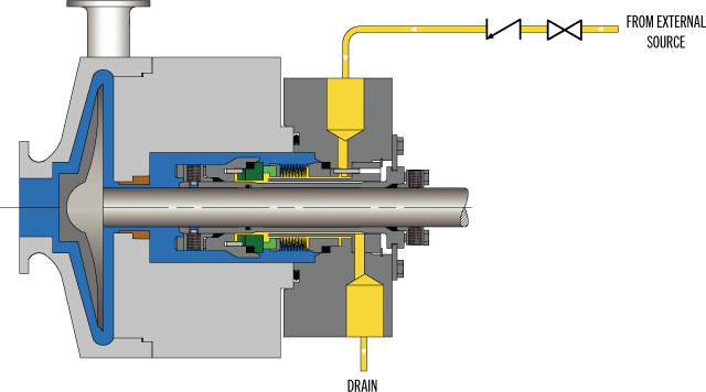
API Plan 62 delivers an external quench fluid to the atmospheric side of the seal. A typical application in a refinery is the prevention of coking on seal faces in hot hydrocarbon service by employing a steam quench. Nitrogen or clean water may also be used to quench or cool and clean the atmospheric side of the seal.
See page 77 of the Mechanical Seal Support Systems Application Guide for additional details and ordering information. Contact your authorized Swagelok sales and service center for information on optional components.

The Type 1604 high-temperature, high-performance Type C, Arrangement 1, API 682 qualified cartridge seal is designed for high-temperature applications such as hot hydrocarbons and crude oil fractionation products. The Type 1604 utilizes a stationary Inconel 718 welded metal bellows with flexible carbon graphite secondary seals. The stationary mounted metal bellows seal is able to handle higher shaft speeds. The Type 1604 utilizes a segmented spring-loaded carbon throttle bushing for effective containment and can come equipped with a retained mating ring for vacuum service. The Type 1604 is often supported by an API Plan 62 quench (steam) and a steam guide for effectively routing of the steam to the seal faces to help eliminate any coke build-up that could occur when sealing hot hydrocarbons.

This paper discusses some important aspects in detail regarding mechanical seals in hydrocarbon, fertilizers and chemical services. Dry gas mechanical seal is out of scope of this paper.
In welded metal bellows mechanical seal spring is not used, instead of it, a metal bellow is used which provides the spring loading necessary to maintain face contact. Welded metal bellows seal design does not require a dynamic shaft packing secondary seal along the shaft. This seal provided no wear on the sleeve. Metal bellows are balanced and have fewer parts.
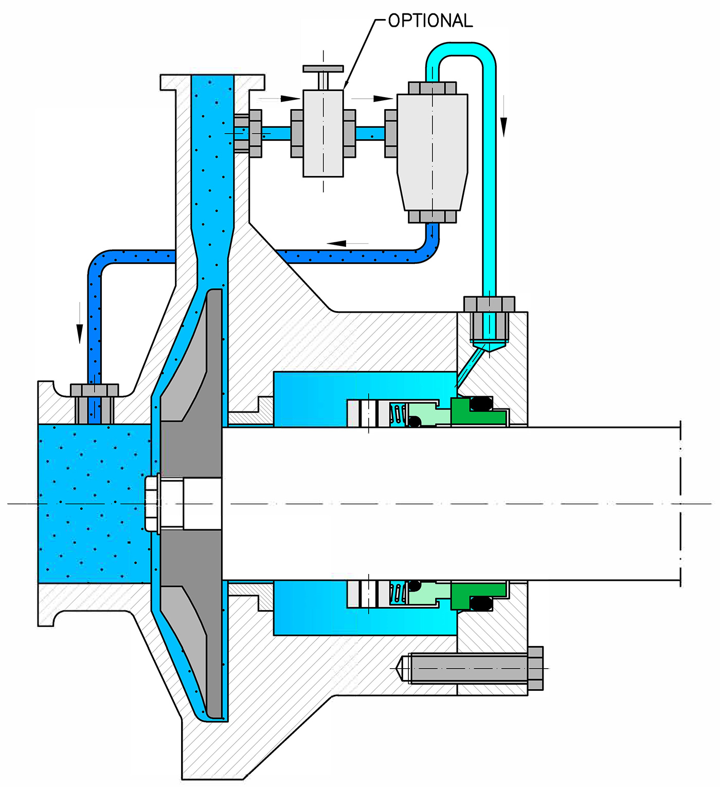
A thermal convection system consists of a supply tank with liquid level gauge and inlet / out lines connected to the seal housing. A vent at the upper most part of the system permits of the release of air or gas from the system prior to start up.
Seal generated heat will flow into the sealing fluid. As the sealing fluid becomes hotter and lighter, it tends to follow upward and is displaced by the cooler, heavier fluid entering the seal cavity from the supply tank. See the seal plans with coolers (Heat exchanger), e.g. Plans 21, 23, 53B, 53C.
These seals are frequently used in applications involving toxic, flammable, carcinogenic and other hazardous fluids because leakage will be contained within the secondary seal if the primary seal fails. The primary seal of a double and tandem seals can be cooled and lubricated by the product delivered through a bypass line from the pump discharge (plan 11). Cooling and lubrication of the secondary seal can be achieved by either induced circulation or by thermal convection. In a double and tandem seal, the secondary seal will retain the primary seal leakage and unless properly drained or vented, this leakage will cause a pressure build up in the secondary seal barrier fluid cooling loop. Here the secondary seal is cooled by thermal convection. Primary seal weepage is continuously vented from the supply tank through an orifice to a flare or other safe disposal system.
Under normal operating conditions, the inboard or primary seal is designed to withstand full product pressure. The out board or secondary seal operates in a suitable buffer fluid at atmospheric or very low pressure.
- If the heat generated by the outboard seal is high, a pumping device (i.e. pumping ring) is usually added to create flow from the outboard seal cavity through the buffer fluid supply tank in a closed loop.
- Tandem seal eliminates icing and freezing of light hydrocarbons and other fluids which could fall below the atmospheric freezing point of water (0 OC). Typical buffer fluids in this allocation are
A tandem increases on line reliability. If a primary seal failure occurs on a critical piece of equipment, the out board seal can take over and can function until maintenance of the equipment can be scheduled. Alarm system can be provided.
When the primary seal fails, pressure build-up activates the pressure switch. The pressure also closes a solenoid valve in the vent line to contain primary seal leakage within the secondary seal system. This switch also sounds an alarm, shutdown system pumps, brings spare pumps in line.
When a mechanical seal fails, leakage occurs. Many options for leakage containment are available. A double or tandem seal can be used, or a single seal can be modified to include a vent and drain feature for collecting leakage.
A vent and drain can be applied to any inside seal by drilling and tapping two opening into the gland ring outboard out board of the stationary inert. Vapour will travel upto the vent to a flare stack or other safe disposal when weepage occur it will drop to the bottom of the gland ring, and exit to the drain, rather than along the shaft sleeve.
Application involving pressure exceeding 600 psig (41 barg) required special designs. To resist the distortion and greater torque that can occur at high pressure seal ring cross sections are made thicker, drive pins and gland size are made oversize. Since the irregularities in the gland surface can be transmitted to the insert and can cause leakage, insert support surfaces in the gland are ground to a 32 RMS finish to insure flatness.
Special design attention is given to seal for high speed applications with shaft speeds in excess of 4500 rpm (23 m/s). Above this speed, dynamic forces begin to exceed the limitations of conventional rotary unit. In such conditions the roles of stationary unit and that of rotary unit are reversed. The springs becomes stationary, the loading of a stationary insert rather than a rotating seal ring. This reduces the movement of secondary seal (packing) and drive pin which could cause excessive wear and fretting damages.
In extremely abrasive or corrosive environment it is sometimes preferable to mate surfaces of identical materials, but this is practical only when extremely hard materials such as Tungsten carbide or Silicon carbide. In these cases, the sealing liquid or product must have adequate lubricity to prevent heat-checking of the faces.
It forms a close clearance with the rotating shaft at the bottom face of the seal housing. Most commercially designed centrifugal pumps have a radial throat clearance of 0.03“to 0.04”. The clearance must be in such a way that it increases the flow velocity of the flush at the throat or to raise the pressure of the sealing liquid.
When heating jacket (e.g. Melt Urea Pump) or cooling jackets (Hot Oil Pump) are incorporated into the seal housing design, the liquid shall be dead-ended in the seal cavity. A restriction device at the throat of the housing will dead-end the sealing liquid and reduce dilution of the product.
Bypass Recirculation Lines are frequently used to insure proper lubrication and cooling of mechanical seals in applications where the pressure acting on the seal are near the vapourization pressure of the product. Since most seal housing pressures are only slightly in excess of suction pressure, the housing usually requires pressurizing to prevent vapourization resulting from the small amount of heat being generated at the seal faces. Bypass lines under discharge pressure will not raise pressure in the seal housing unless restriction at the housing throat.
In order to exclude product from seal housing, a fluid velocity of 15 ft /sec (4.5 m/sec) must be created at the seal housing throat. With a 2”(0.05m) diameter shaft and normal throat clearances of 0.003” to 0.004”, flushing fluid flow rate of 10 GPM ( 2.27 m3/h) are required to obtain the desired velocity.
The primary purpose of a restriction device at the throat of the seal housing is to reduce the radial clearance at the throat and thereby reduce the amount of flushing liquid required to create the required velocity.
Most mechanical seals are designed to operate in liquid, and the seal faces must be immersed in a liquid from the very beginning. Dry operation will score and damage the seal faces.
Equipment shall not be run dry while checking motor rotation. Full speed operation for a few moments under dry condition will severely damage the seal faces.
The seal housing shall be vented before start up. Even when a pump has a flooded suction, air may be trapped in top portion of the seal housing after the initial liquid purge of the pump. This is especially important in vertical installation.
Cooling, heating, flushing lines shall be turned on. Cooling and heating lines shall be always left open especially if a hot product is passed through a pump (e.g. Hot oil pump) or if the product is likely to solidify upon cooling (e.g. Urea pump). In the case of hot operational unit that is shut down at the end of each day, cooling lines shall left open at least long enough for the seal area to cool below the temperature limits of the materials in the seal.
Through chilling procedure is necessary in installations involving products like Liquid Petroleum Gases (LPG) and Anhydrous Ammonia (NH). Start-up is critical with such products, and they must always be kept in a liquid state in the seal area. These products require pressure in the seal area which is 2 to 3 bar greater than the vapour pressure of the product.
A squealing noise at start indicates that the seal faces are running dry. A bypass line, i.e. plan 11, from discharge to the seal chamber will supply fluid to the seal. If suction is lost during start up, the stuffing box chamber shall be vented before restarting the machine. It is normal for a new seal to leak somewhat at start up. Allow a reasonable time for seal faces to “wear-in” to each other. However if leakage does not decrease, the secondary seal may be damaged or the seal faces may be warped out of flat.
Cavitation occurs when the product exceeding its vapour pressure at the inlet eye of the impeller. To correct this the pump suction line may have to be enlarged or some other means to achieve the suction head. Cavitation can cause damage to both pump and seal. Cavitation can cause shaft vibration, shaft defection, and bearing failures. It can cause excessive heat built up in the stuffing box, eventual loss of liquid film between the seal faces and finally seal failure.
A rapid change in fluid state from liquid to gas is called flashing. In a dynamic seal this can occur when frictional energy is added as fluid passes through the primary sealing faces, or, when fluid pressure is reduced below the fluid’s vapour pressure because of a pressure drop across the sealing faces.
Closing the discharge valve of the pump causes the greatest amount of shaft defection in a single stage end suction pump. The resulting shaft defection and overheating, in turn, causes seal failure.
In fact some liquids can boil off or flash to vapour in the seal chamber from the normal frictional heat at the rubbing faces plus the heat generated from operating at or near shutoff.
In order to provide the end user with a high degree of confidence that the seal type being offered shall perform is to the scope of seal manufacturer qualification test as per API 682. The qualification does not constitute an acceptance test. This qualification test is to provide the end user with factual proof of seal’s ability to perform reliably in various environments.
Each seal types (A, B, C) from each seal application group shall be tested on an appropriate test rig by seal manufacturer. The test fluids are selected to model the behaviour of the fluids described in selection procedure. The properties of the test fluid are representative of the properties of the fluids shown in the application groups (i.e. viscosity, corrosiveness, crystallization, vapour pressure, hydrocarbon, non-hydrocarbon).
The purchaser shall evaluate the results of qualification test to determine if the tested seal type has met all the requirements of this standard API 682.
It is the default seal flush plan for all single seal. In this plan product is routed from pump discharge to the seal chamber to provide cooling for the seal and to vent air/vapour from the seal chamber. It is the most commonly used flush plan for clean general service equipment. For high head application, careful consideration shall be given to calculation of the required flush flow rate.
Plan 13 is the standard plan for vertical turbine pumps since they have the discharge at the top of the pump where the seal is located These pumps normally are arranged so that the seal chamber meets full discharge pressure, for vertical pump, seal chamber pressure is equal to discharge pressure. Due to this there is no pressure differential, i.e., in vertical pumps, pressure differential (Discharge pressure minus Seal chamber pressure) is virtually nil. In this plan, product is routed from seal chamber to back to the pump suction to provide cooing for the seal and to vent air/ vapour from the seal chamber.
(Industry has considerable negative experience with Plan 21. Plan 21 is not a preferred plan, either by API or many users, due to the high heat load put on the heat exchanger. Plan 21 is a cooled version of Plan 11. The product from pump discharge is directed through an orifice, then to a heat exchanger to lower the temperature before being introduced into the seal chamber. A Plan 23 is preferred)
Plan 14 = Plan 11(discharge to seal chamber through orifice plate + Plan 13 (vertical turbine pump- seal chamber to pump suction through orifice plate). This plan is excluded from API 682.
Plan 23 is a closed loop system using a pumping ring to circulate product through a heat exchanger and back to the seal chamber. Here the cooler only cools that fluid Plan 23 is the plan of choice for all hot fluid services including boiler feed water pump, hot oil circulation pump and many hydrocarbon services. Hot water has very low lubricity above 80 oC resulting in high seal face wear. Reduced temperature through heat exchanger improves lubricity and improves vapour pressure margin. Close clearance throat bushing is recommended to reduce mixing of hot product with cooler closed loop system.
Plan 31 is variation of Plan 11, where an abrasive separator (cyclone separator) is added to the flush line. In this plan, the product is introduced to the abrasive separator from the discharge of the pump.
Advantages of this plan are unlike a strainer or filter, the abrasive separator does not require cleaning. Solids are removed from the flush stream keeping the seal clean. The solids particles are centrifuged and routed back to suction. The clean fluid goes to the seal chamber thus completing the seal flush. Typically the cyclone separator requires a minimum pressure differential of 15 psi (1 bar) to operate properly. High pressure differentials may require the addition of an orifice upstream of the cyclone. This plan is specified only for services containing solids with a specific gravity twice or more than that of process fluids.
Fluid is injected from an external source into the seal chamber. The external flush shall be continuous and reliable even during non-standard situations such as stat-up, shutdown, etc. This plan is almost always used in conjunction with a close clearance throat bushing which can function as a throttle device to maintain an elevated pressure in the stuffing box or as a barrier to isolate the pumped product from seal chamber. When an outside flush source is used, concerns regarding product dilution and/or economics must be considered by the user.
This plan 52 or arrangement 2 unpressurized dual seal arrangement systems are used in services where no leakage to atmosphere can be tolerated. This plan consists of dual mechanical seals with a buffer fluid between them.
Buffer fluid is and externally supplied fluid, at a pressure lower than the pump seal chamber pressure, used as a lubricant and/or to provide a diluent in an Arrangement 2 seal.
The buffer fluid is contained in a seal pot which is vented to a vent system, just maintain the buffer fluid pressure close to atmosphere. Inner seal leakage will be product leakage into the buffer fluid. There will always be some leakage.
Plan 52 works best with clean, non-polymerizing products which has a vapour pressure higher than the buffer fluid pressure. These products will flash in the seal pot and the vapour can escape in the vent system. If the product has a vapour pressure lower than the buffer fluid or seal pot pressure then the leakage will remain a liquid and will contaminate the buffer fluid.
Should an inner seal leak not be detected early, the heaver process fluid will displace the buffer fluid and can result in the area between the two seals being completely filled with product. In that case an outer seal leak can result in product being released to the atmosphere.
Plan 52 is discouraged for dirty or polymerizing products as well. Cooling coils in the reservoir are available for removing heat from the buffer fluid.
This plan 53A or arrangement 3 pressurized dual seal arrangement systems can be used in services where no leakage to atmosphere can be tolerated. Plan 53A uses an external reservoir to provide barrier fluid which is pressurized to a higher pressure, usually 20 psig, than the pump seal chamber pressure for a pressurised dual seal arrangement. Reservoir pressure is produced by a gas, usually nitrogen. Flow is induced by a pumping ring.
Plan 53 A is used over plant 52 for dirty, abrasive , or polymerizing products which would either damage the seal faces or cause problems with the buffer fluid system if plan 52 were used.
Plan 53 is dependent of seal pot pressure maintained at the proper level. If the seal pot pressure drops, the system will begin to operate like plan 52, or unpressurized dual seal, which does not offer the same level of sealing integrity. Especially the inner seal leakage direction will be reversed and the barrier fluid become contaminated with the process fluid that result possible seal failure.
Plan 53B previously termed 53 Modified uses a bladder accumulator to isolate the pressurising gas from the barrier fluid. A heat exchanger is included in the circulation loop to cool the barrier fluid. Flow is induced by a pumping ring.
Should the loop be contaminated for any reason, the contamination is contained within the closed circuit. The make-up system can supply barrier fluid to multiple dual pressurised sealing systems. The bladder accumulator isolates the pressurising gas from the barrier fluid to prevent gas entrainment. The heat exchanger can be water cooled, finned tubing, or an air-cooled unit based upon the system heat load.
Plan 53C uses a piston accumulator to provide pressure to the system. It uses a reference line from the seal chamber to provide a constant pressure differential over the chamber’s pressure. A water- or air-cooled heat exchanger provides for barrier fluid cooling. Flow is induced by a pumping ring.
General: Plan 54 systems can be custom engineered to suit application requirements. Systems can range from the direct connection from other process streams to complex API 614 systems.
In plan 62 a quench system is brought from an external source to the atmospheric side of the seal faces. The quench fluid can be low pressure steam, nitrogen or clean water.
It is used in selected single seal and also double seal application to exclude the presence of oxygen to prevent coke formation (i.e. hot hydrocarbon application) and to flush away undesirable material build up around the dynamic seal components (i.e. caustic & salt services). Steam quenches on hot services to retard coking, nitrogen quenches on cold or cryogenic service to prevent icing, or water quench to prevent crystallization or accumulation of product on the atmosphere side of the seal.
AESSEAL ® is a Registered Trademark of AESSEAL plc AESSEAL plc recognises all trademarks and trademark names as the property of their owners. Copyright © 2007 AESSEAL plc Ref: L-UK/US-ORACLE-19 AES/DOC/IN 5119 10/07

Pumping of low-temperature and cryogenic fluids requires specific and unique engineering technologies for the shaft sealing system. When correctly applied, these technologies provide the containment and reliability to meet pumping equipment operators’ requirements.
Due to their extreme sub-zero temperatures, low-temperature hydrocarbons and liquefied atmospheric gases pose significant challenges to pumping, and particularly to the specification of their shaft sealing systems. To provide long-term reliability while ensuring that these pumped fluids are safely contained, the designs of the shaft seals used in cold-fluids pumps are often highly specialized.
For example, low temperatures have significant implications for the choice of materials used in the seal construction. Metals become increasingly brittle as the temperature is reduced; therefore, thermal constriction and expansion must be factored. The volatility and flammability of low-temperature hydrocarbons pose special challenges for the design of pump shaft seals, as well as for the release of hazardous emissions to the atmosphere. Liquefied oxygen, with temperatures much colder than these hydrocarbons, is a strong oxidizer and can cause certain materials to spontaneously combust.
Low-temperature hydrocarbons are commonly pumped with API 610 (VS6) vertical multistage double-casing pumps that feature a warming chamber, known as a cofferdam (Fig. 1), which thermally isolates the shaft seal from the cold pumped fluid. Cofferdams enable a greater range of shaft sealing solutions to be used on these pumps, utilizing traditional sealing technology.
A cofferdam is a chamber between the pump discharge and the mechanical seal that is connected to the pump suction, or the vessel from which the pump is drawing suction. Ambient heat surrounding the pump, together with energy from the shaft and bearings, causes the liquid in this chamber to vaporize into a gas, which forms an insulating barrier between the seal and the process fluid. Cofferdams can be incorporated only into vertical pump designs.
Although vertical arrangements are common, various horizontal pumps can also be used. In these types of pumps, the shaft seal is in direct contact with the cold-pumped fluid; therefore, selection of the seal materials for low-temperature operation becomes more critical.
Similar to pumping equipment for low-temperature hydrocarbons, pumps used for liquefied atmospheric gases have a combination of vertical multistage pumps, together with horizontal single-stage pumps. These systems generally do not follow API pump design standards.
However, as the temperatures of liquefied atmospheric gases are much colder than those at which hydrocarbons are pumped, cofferdams cannot be used on these pumps. Although a mixture of vertical and horizontal pumps is commonly used at air liquefaction plants, mobile trailer truck unloading pumps are almost exclusively overhung single-stage pumps, either with direct-drive or speed-increasing gearboxes.
For pump designs where the mechanical seal is immersed in the pumped fluid, the vapor pressure margin in the seal chamber becomes critical. Where the vapor pressure margin is low, the heat energy from the mechanical seal faces can vaporize the fluid around the seal and in the seal interface, resulting in dry running of the seal. In this situation, a dual-pressurized seal is required. A dual-pressurized seal provides a stable barrier fluid to lubricate the seal faces, thereby negating the effect of vaporization of the pumped liquid at the seal faces.
API Plan 53B and 53C barrier systems are commonly selected for dual-pressurized seals to provide a source of warm, clean and stable barrier fluid to the mechanical seal. When an API Plan 53C system is selected, extra care should be taken to ensure that the pressure-amplifying piston and rod seals are insulated from exposure to cold temperatures.
The availability of suitable barrier fluids becomes limited at low temperatures, as the viscosity of many fluids becomes too high at the seal chamber operating temperatures. Mono- and di-ethylene glycol mixtures with water can be used down to temperatures of –29°C (–20°F). Alcohols, such as propanol (propyl alcohol), are suitable for even colder temperatures reaching –70°C (–95°F). Synthetic oils can also be used; however, careful consideration to their pour point is required, and a heating system may be needed to warm the barrier fluid to maintain a suitable viscosity.
When sufficient vapor pressure margin exists within the seal chamber, a dual-unpressurized seal can be selected. Typically, these designs feature a dry-sliding containment seal fitted with API Plan 76, or a combination Plan 72 and 76. These seal arrangements have the advantage of removing the low-temperature limitation of barrier fluid selection.
Pump designs utilizing a cofferdam require a dual-pressurized mechanical seal, as the seal chamber contains no liquid to lubricate the mechanical seal faces.
Icing, due to condensation of atmospheric humidity, can create a problem for sealing systems handling cold hydrocarbons. Since condensing water expands as it freezes, it can interfere with the operation of the mechanical seal if it reaches the seal’s operating mechanism. Extra protection should be applied to equipment exposed to atmospheric elements, such as rain. An API Plan 62 using a dry nitrogen quench can displace atmospheric humidity, thereby protecting the mechanical seal from these effects.
In applications handling liquefied atmospheric gases, pump seal reliability takes precedence when selecting a shaft sealing system. Unlike hydrocarbons, emissions of gases to the environment by liquefied atmospheric gases pose relatively minor hazards and, therefore, are not as critical a factor as seal reliability.
Two commonly employed shaft sealing technologies are used in pumps handling liquefied atmospheric gases: single mechanical seals and segmented bushings.
Single mechanical seals.The most common solution for pumps used in air liquefaction plants and mobile-transportation unloading pumps is the single mechanical seal. The major difference between the two is that the mobile unloading pumps tend to be smaller and often use non-cartridge seals. Cartridge seals are commonly found in larger machinery at air liquefaction plants. Single mechanical seals fall into two sub-categories: contacting wet seals and vaporizing liquid gas seals.
Contacting wet seals utilize a metal bellows to provide elastomer free-axial flexibility. Seal face materials typically include filled tetrafluoroethylene running against a tungsten carbide or hard-coated, stainless steel mating ring.
Vaporizing liquid gas seals (Fig. 2 and Fig. 3), similar in construction to contacting wet seals, feature engineered seal-face topography that allows the controlled vaporization of the pumped atmospheric gas to produce a highly reliable seal that exhibits controlled, low-level leakage rates.
Segmented bushings.A segmented bushings sealing configuration is often found in vertical multi-stage pumps at air liquefaction plants. The design provides a controlled leakage by breaking down the sealed pressure over a series of tightly controlled bushing clearances. Leakage rates are higher than those of mechanical seals; however, these leakage rates are often considered acceptable by this industry.
As mentioned, low temperatures have significant implications for the choice of materials used in the seal construction. This is especially true for elastomers applied in seals for pumps handling low-temperature hydrocarbons. Depending on the material grade used, elastomers have a variety of minimum temperature limits, but none can survive dynamic operation at true cryogenic temperatures.
Engineered polymer seals are an option at temperatures below the limits of elastomers; however, many of these designs will not function with pressure reversals applied to the sealing ring, which may be required in the mechanical seal design when support system failures occur.
Elastomers can survive at significantly lower temperatures below their operational limits when the seals are not in operation (i.e., static); however, they must be warmed up prior to operation. Commissioning of shaft seals containing elastomers must be completed carefully to ensure that equipment is at the correct temperatures before startup. Blowdown—the rapid depressurization of a vessel/pipeline—is one situation that can create excessively low temperatures for mechanical seal elastomers.
Thermal expansion and contraction are also considerations. The cavities in which elastomers or engineered polymer seals are installed will change with decreasing temperatures, as well as the dimensions of sealing elements installed in these cavities. Additionally, clearances between dissimilar materials, such as bushings, will require review. Mechanical seal manufacturers take these factors into consideration during the design of the mechanical seal for these cold services.
Since pumping equipment is often used interchangeably between different atmospheric gases, sealing of liquefied atmospheric gases presents some unique challenges to the selection of materials.
Liquefied oxygen is a strong oxidizer and can cause certain materials to spontaneously combust. Additionally, any organic contaminates on the seal can lead to spontaneous combustion, including metal cutting fluids, fibers from cleaning rags, and even oils from human fingerprints. To meet oxygen service requirements on seals, stringent cleaning specifications must be employed to ensure that the seal is free of any contaminates that may create a fire hazard while in service. Additionally, the materials of construction must include materials that are compatible for use in oxygen service.
Aluminum alloys should be avoided, as they can become hazardous when their protective oxide film is stripped from the material, such as when abrasion occurs. Lubricants used in the assembly and operation of the mechanical seal must be free of hydrocarbons and compatible for use in oxygen service. Packaging of the seal should also be suitable to preserve the cleanliness of the seal prior to installation into the pumping equipment, which must be performed in a suitably clean environment.
Of the many pump mechanical seal applications in use throughout various industries, those that deal with low-temperature and cryogenic processes rank among the more challenging.
It is critical to keep these seals, which handle low-temperature hydrocarbons and liquefied atmospheric gases, in optimal operating condition to ensure that the pumped fluids are safely contained, while providing long-term reliability. HP
Mark Savage is a Product Group Manager at John Crane, responsible for the application, design and development of metal bellows seals for pumps, compressors and rotating machinery. He has worked in the sealing industry for 25 yr and has been involved with the development of best practices for shaft seals and their support systems. Mr. Savage holds a BE degree in mechanical engineering from the University of Sydney, Australia. He is a member of the Fluid Sealing Association and Vice Chair of the Association’s Mechanical Seal Division, Chair of the Mechanical Seal Technical Committee and Vice Chair of the Government Relations Committee. He is also a member of NACE International and the Society of Tribologists and Lubrication Engineers (STLE). Mr. Savage has authored several publications on mechanical seals and support systems and their application to minimize environmental impact.


 8613371530291