
api plan for double mechanical seal pricelist
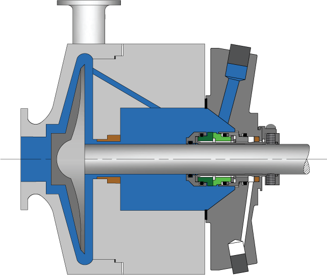
Pumping processes involving toxic or hazardous fluids that can’t risk leakage because of stringent environmental regulations require a double mechanical seal. Compared to a single mechanical seal, a double seal gives you significantly greater protection against leaks. With a double mechanical seal, you have an arrangement of two mechanical seals (a primary or inboard seal and a secondary or outboard seal) in series—back-to-back, tandem, or face-to-face. Each seal has a rotating (R) surface and a stationary (S) seal surface. These seals can be arranged in one of three patterns.
In a back-to-back arrangement, the stationary seal faces are positioned back-to-back with the rotating seal faces on the outside. The back-to-back arrangement is easy to install and used for many general pumping applications.
The tandem arrangement has the two pairs of seals mounted with the same orientation. This arrangement is preferred for toxic or hazardous applications because the outboard seal provides full pressure back-up, allowing the outboard seal to back up in the event of an inboard seal failure.
In the face-to-face arrangement, the rotating seal faces share a common stationary seal face. This arrangement is useful when equipment space is too constrained to permit back-to-back or tandem seal arrangements.
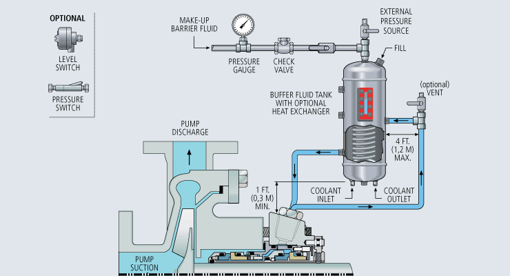
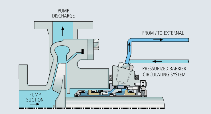
The American Petroleum Institute (API) Standard 682 classifies double mechanical seals into two configurations—pressurized and unpressurized. The pressurized arrangement has a barrier fluid delivered to the double mechanical seal by a seal support system. The barrier fluid is delivered at a higher pressure than the process fluid and must be chemically compatible with the process fluid as it will lubricate the inboard seal faces and mix with the process fluid. The unpressurized arrangement has a buffer fluid delivered to the double mechanical seal by a seal support system. The buffer fluid is delivered at a lower pressure than the process fluid.
The barrier and buffer fluids you use can be liquid or gas. They provide lubrication and help maintain the required operating temperature of the seal faces. The typical choices are water and water/glycol mixtures, low-viscosity petroleum or synthetic oils, kerosene, diesel, and nitrogen.
To gain a better understanding of the differences between the uses of barrier and buffer fluids, let’s look at two common API plans for double mechanical seals—API Plan 52 Buffer Fluid Seal Pot and API Plan 53A Barrier Fluid Seal Pot Pressurized by Nitrogen.
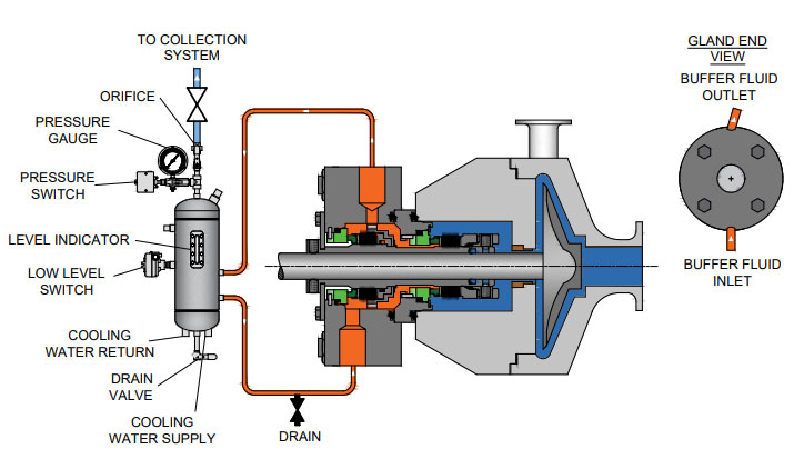
API Plan 52 takes buffer (unpressurized) fluid from a reservoir (seal pot), delivers it to the seal chamber, circulates it between the inboard and outboard seals using a pumping ring located driven by shaft rotation, then returns the fluid to the reservoir. In the event of an inboard seal failure, process fluid leaks into the seal chamber. When that occurs an increase in buffer fluid pressure and/or level alerts operators to the problem. The outboard seal, however, contains leakage until maintenance can replace the damaged seal.
This plan can include cooling coils in the reservoir to maintain the required buffer fluid temperature, visual or mechanical fluid level indicators, pressure and level transmitters, and connection to a collection system and buffer fluid replenishment source.
The overall design of this API plan for a double mechanical seal is relatively simple in comparison to other plans. Design decisions involving tubing size, length, geometry, type (carbon vs stainless steel), buffer fluid type, and volume of the buffer fluid reservoir are critical in maintaining the proper operating environment for the double seal. If you don’t have this expertise in-house, work with an experienced, local seal support system vendor to ensure the API Plan 52 is designed to meet your specific pumping requirements.
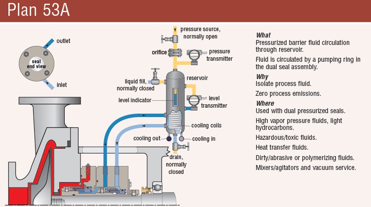
API Plan 53A is conceptually similar to API Plan 52 with the difference that the fluid being circulated between the double mechanical seals is under pressure. A pumping ring is used to circulate the fluid. The reservoir that contains the barrier fluid is pressurized by plant nitrogen. Reservoir pressure should be set a minimum of 20 to 25 psi (1.4 to 1.73 bar) above the maximum seal chamber pressure, allowing the barrier fluid to leak (and lubricate) across the inboard seal faces into the process fluid. For this reason, the barrier fluid must be chemically compatible with the process fluid.
Because barrier fluid is depleted as it moves across the inboard seal faces, it needs to be replenished. This can be done manually or automatically by way of a system that serves multiple pumps. API Plan 53A design options include reservoir type and volume, cooling coils, fluid level and pressure indicators, and transmitters to alert to level or pressure changes that indicate seal failure.
When you choose an API plan for a double mechanical seal, your primary decision is between a buffer or barrier plan. I’ve highlighted two of the API plans for double mechanical seals above to show the basic differences. There are multiple API plans for double mechanical seals to choose from—pressurization from bladder or piston accumulators, plant nitrogen delivered directly to the seal chamber, and custom-engineered external systems. Your choice will be determined by the process fluid and pumping conditions and the type of double mechanical seal your vendor recommends.
With this information in hand, it’s best to work with an experienced local seal support system vendor. They’ll be able to meet with you on-site to review the specifications for the pumping process, the pump, and the double mechanical seal. They’ll evaluate your existing infrastructure and its influence on seal support system design. Based on this information, they’ll then design the seal support system to meet the specific pumping requirements.
If you work with a global vendor like Swagelok, based on the design, we can quickly assemble and thoroughly test the API plan at our local facilities prior to delivery. We’re also conveniently available for follow-up consultations, on-site, remotely, or by way of a quick phone call.
For well over 50 years, Swagelok has worked closely with Northern California process industries to confidently choose the right API plans for pumping needs. Our locally based Field Engineers and certified technicians provide field verification of your seal support requirements, designs based on best practices gained from global experience.
To find out more about howSwagelok Northern California can help you choose the right API plan for double mechanical seals, as well as process and atmospheric side seals,contact our team today by calling
Morgan holds a B.S. in Mechanical Engineering from the University of California at Santa Barbara. He is certified in Section IX, Grab Sample Panel Configuration, and Mechanical Efficiency Program Specification (API 682). He is also well-versed in B31.3 Process Piping Code. Before joining Swagelok Northern California, he was a Manufacturing Engineer at Sierra Instruments, primarily focused on capillary thermal meters for the semiconductor industry (ASML).
-1.png?width\u003d360\u0026name\u003dimage2%20(3)-1.png)
Please contact AESSEAL Systems Division for further details. Tel: +44 (0)28 9266 9966 Email: systems@aesseal.com For more information, and a video demonstrating the piping plan in operation, select a plan below
Pressurised barrier fluid circulation in outboard seal of dual seal configuration through a seal support system. Circulation is maintained by using pumping ring in running condition and with thermosyphon effect in stand still condition.
Depressurised buffer fluid circulation in outboard seal of a dual seal configuration through a seal support system. Circulation is maintained by using pumping ring in running condition and by thermosyphon effect in stand still condition.
1. Keep the sealant vessel vent continuously open, which is necessary to maintain buffer fluid pressure close to atmospheric pressure and vent the vapors to flare.

Multiple mechanical seal failures in a crude distillation unit (CDU) resulted in total losses of $3 MM in a refinery since its startup in January 2015. The maximum seal life achieved did not exceed 6 mos, which was much shorter than the American Petroleum Institute (API) 682 “Advancements in Mechanical Sealing” goal of 3 yr of seal life.
Multiple mechanical seal failures in a crude distillation unit (CDU) resulted in total losses of $3 MM in a refinery since its startup in January 2015. The maximum seal life achieved did not exceed 6 mos, which was much shorter than the American Petroleum Institute (API) 682 “Advancements in Mechanical Sealing” goal of 3 yr of seal life.
The root causes of failure for the mechanical seals for 16 hot hydrocarbon service pumps (with operating temperatures in excess of 250°C) are discussed here, and solutions are demonstrated to eliminate failures and improve plant reliability.
CDU hot pumps are equipped with API seal flushing Plan 32 (injection to seal chamber from an external source) and API seal flushing Plan 54 (pressurized external barrier fluid). API Plan 32 utilizes heavy vacuum gasoil (HVGO) that is supplied at 1.7 barg above the seal chamber pressure at 110°C. API Plan 54 utilizes light vacuum gasoil (LVGO) that is supplied at 1.7 barg greater than that of Plan 32 pressure at 110°C. For example, if the seal chamber pressure is 5 barg, Plan 32 should be supplied at 6.7 barg (5 + 1.7), and Plan 54 should be at 8.4 barg (6.7 + 1.7).
The flowrate for each API plan varies, depending on the pump service. The HVGO utilized for Plan 32 is produced from the CDU and supplied to the CDU hot pumps by a common system, as shown in FIG. 1. The LVGO utilized for Plan 54 is produced from the CDU and supplied to the CDU hot pumps by a common closed system (FIG. 2).
Mechanical seal failure data was collected from a computerized maintenance management system (CMSS), and selection criteria were set to concentrate the focus on the “bad actor” pumps. Selection criteria included an operating temperature that exceeded 250°C. The seal failure history is indicated in TABLE 1, which shows a total of 41 seal failures that occurred in 2015 vs. 25 failures in 2016. The large discrepancy in failures between 2015 and 2016 was due to a startup and commissioning period in early 2015, during which time the refinery was suffering from system dirt, operational upsets and various commissioning problems. While seal failures were reduced in 2016, equipment mean time between failure (MTBF) and seal life were unsatisfactory for refinery maintenance key performance indicators (KPIs) and targets.
A root cause analysis (RCA) was conducted in April 2016 to identify the root cause of failure for CDU bad actor pumps to eliminate seal failures and enhance equipment reliability. This RCA evaluated all possible seal failure causes including, but not limited to, the following major possible causes:
Almost 90% of the dismantled failed mechanical seals experienced either coke formation or sludge in the outboard seal side (secondary seal provided with Plan 54 barrier fluid). Most of the findings showed coke particles trapped on the rotating face along the outboard seal side and bellows, as shown in FIGS. 3 and 4.
Figs. 3 and 4. Almost 90% of the dismantled failed mechanical seals experienced either coke formation or sludge in the outboard seal side and bellows.
The RCA team also reviewed the design basis and barrier fluid (API Plan 54) selection criteria. It was concluded that LVGO is not a compatible seal barrier fluid, as the most desirable viscosity range for any hydrocarbon seal barrier is between 2 cSt and 10 cSt in accordance with API 682 (shaft sealing systems for centrifugal and rotary pumps). To achieve this viscosity range, the operating temperature for the LVGO was increased during the design phase of the refinery to 110°C, which contradicts the refinery standard that limits the barrier fluid for Plan 54 to a temperature of 70°C.
In addition, barrier fluid selection was reviewed for other process units within the refinery that contain pumps with similar operating parameters and that utilize API seal Plan 32 and Plan 54, such as hydrocracking (HCK) units and delayed coker units (DCUs). Similar pumps within HCK units utilize diesel for both API plans at 50°C–60°C, whereas DCU pumps utilize heavy coker gasoil (HCGO) at 60°C and light coker gasoil (LCGO) at 60°C for Plan 32 and Plan 54, respectively. Seal failures for both units, along with failures modes, were also evaluated and were found to be satisfactory.
The RCA concluded that the direct cause of the mechanical seal failures was due to coke formation in the outboard seal (atmospheric side), which impacted the seal bellows and caused the seal faces to open. It was also concluded that the root cause of failure was due to the improper selection of API seal Plan 54 (LVGO), as this type of hydrocarbon has been proven to form coke at 110°C on the atmospheric side of the seal.
The effect of coke formation in mechanical seals can be understood from a mechanical seal balance ratio. Mechanical seal vendors design the seal face with a balance ratio to minimize heat generation between seal faces. This seal ratio also impacts seal faces opening and closing forces. The seal balance ratio normally ranges from 0.6–0.9.
When coke forms and solidifies on the seal faces, the seal outer diameter will increase, resulting in a higher opening force that, in turn, leads to excessive leakage, as shown in FIGS. 5 and 6.
The RCA recommended changing the barrier fluid from LVGO to diesel (supplied from the CDU atmospheric column). The API seal Plan 54 common pumps (FIG. 2) were evaluated to accommodate this change, and it was found that diesel was unsuitable for these pumps at high temperatures—the pumps were designed for LVGO, which has a relatively higher viscosity than diesel. To overcome this problem, it was decided to cool the diesel to 50°C to increase fluid viscosity.
After the refinery turnaround, the CDU bad actor pumps were monitored closely for 13 mos following the refinery startup in December 2016. Seal failures were determined to be almost entirely eliminated, and seal life was increased. TABLE 2 shows the total number of seal failures since diesel was utilized with API Plan 54. The number of failures was reduced drastically to two, compared to the same period in 2016. For example, pump 110-G-0016 C (which was considered as the most troublesome CDU bad actor pump) had zero failures compared to eight failures since the refinery startup. Although some failures were recorded since diesel was utilized as barrier fluid, it is strongly believed that these failures were due to remaining LVGO traces in the seal internals.
In addition, the RCA identified areas of improvement with regard to quality assurance and quality control procedures, which had been found to be less than adequate. The RCA team developed mechanical seal replacement procedures that focused on improving the following important aspects in accordance with API 686 “Recommended Practices for Machinery Installation” and equipment OEM manuals:
Ahmed A. Telmesani is a Maintenance Engineer for Yanbu Saudi Aramco Sinopec Refinery (YASREF). His responsibilities and areas of focus include eliminating failures, enhancing systems reliability, power saving initiatives, early failure detection and continuous preventive maintenance review and enhancement. He previously spent 10 yr with Saudi Aramco. Mr. Telmesani earned his BS degree in mechanical engineering from King Fahad University of Petroleum and Minerals (KFUPM) in Dhahran, Saudi Arabia.
FLUSH PLANS FOR MECHANICAL SEALS – INTRODUCTIONPumps and seals are being installed into increasingly difficult services. Forsuccessful operation of mechanical seals, the environment and care of the sealsrequire more sophisticated seal chambers and flushing arrangements. This sectionof the Dean Pump Price Book is designed to allow the application and pricing offlush plans suitable to meet the requirements for the mechanical seal.The American Petroleum Institute (API) has defined certain seal flusharrangements known by their plan numbers. Later, the flush plans developed forthe ANSI standard followed suit and placed the digits "73" in front of the API plannumber to achieve some standardization within the process industry. Thus, APIplan 11 becomes and ANSI Plan 7311.Dean Pump has worked with many engineering houses and customers over theyears and has developed a great deal of experience with sealing systems. WhileDean will quote any flush system requirement as requested by a particularcustomer, it has been found that the API/ANSI systems generally meet or exceedmost customer requirements. In addition, Dean Pump developed the Seal GuardEnvironment systems that provide the ultimate mechanical seal flush plan. Forsystems that do not require ANSI/API flush plans, Dean Pump has also includedthe P1200 loop, which is a basic low cost flush plan to satisfy the economyminded customer.The experience of Dean Pump is contained in these price pages. Many of theflush plans are divided into "Toxic/Flammable" and "Non-Toxic/Non-Flammable“services. The information on these plans along with the details described in the"Special Notes" section can be used as a guide in quoting and discussing optionswith customers. The "fine print" in the Special Notes section provides a multitude ofdetails about each flush system. For example, a customer requesting all socketwelded connections can not have every connection welded. Some accommodationmust be made for disconnecting the system. Being aware of the requirements ofthe customer and the manufacturing limitations of the product is extremely helpful.API flush plans are based on the 7 th Edition of API610. Newer versions of the APIspecifications has limited the cooling and flushing options available.Finally, if there are any doubts, questions, or comments, please feel free to call theFactory and the seal vendor.Effective: FEBRUARY 2011 • Replaces: NEWPage 1
SEAL GUARD SYSTEMS – PRODUCT DESCRIPTIONSeal Guard systems are designed to provide a clean liquid for seal flushing thatprovides protection for the mechanical seal in the pump seal chamber. Dean Pumpoffers two basic systems to guard against mechanical seal failure. These systemswill also help to prolong the life of the seal. Both systems are filtration systemsinstalled into the seal flush lines to remove stray abrasive particles which causeseal face wear.Seal Guard A - is designed for filtration only. Particles larger than 10 microns arefiltered from the system using clean-able or replaceable 316SS woven filterelements.Seal Guard B - is designed for high temperature applications and includes a heatexchanger installed ahead of the replaceable filter elements for both filtration andtemperature control.Seal Guard systems are most often used with MIN-FLO Bushings in the pump sealchamber. These bushings restrict the flow from the seal chamber back into thepump during operation and increases the effectiveness of the Seal Guard system.Seal Guards can be used on any pump product line. Their sale is not limited toDean Pump products. Seal Guards are hydrostatically tested but do not meet anyindustrial standard and are not for application to API610 series pumps. Seal Guardapplications must be limited to iron or steel pumps and are not suitable forapplications that require alloy materials.The Seal Guard system is fully described in Bulletin A2000.Effective: FEBRUARY 2011 • Replaces: NEWPage 2
SEAL GUARD SYSTEMS – (See Note #1)Model A Series – Filtration Only (See Note #2)Mounted on Pump BaseplateModel Description List PriceA500T A Series Seal Guard - Filtration - Threaded Connections $4,483A500F A Series Seal Guard - Filtration - Flanged Connections C/FA700T A Series Seal Guard - Filtration - Threaded Connections C/FBD500TB500TModel B Series – Filtration and Cooling (See Notes #2 & #3)Mounted on Separate BaseplateModel Description List PriceBD200T B Series Seal Guard - Cooling & Filtration - $5,248Threaded Connections & Duplex FilterB400T B Series Seal Guard - Cooling & Filtration - $5,248Threaded Connections & Simplex FilterB400F B Series Seal Guard - Cooling & Filtration - C/FFlanged Connections & Simplex FilterB500T B Series Seal Guard - Cooling & Filtration - $6,226Threaded Connections & Simplex FilterBD500T B Series Seal Guard - Cooling & Filtration - $8,240Threaded Connections & Duplex FilterNotes:1. Seal Guard systems are not rated for API application and are suitable for pumps in steel or iron construction only. Do notuse for 316SS or other alloy applications.2. The product description letters and numbers are as follows:First Letter - Seal Guard Series A - Filtration Only; B - Cooling and Filtration. (The letter D following in the second positionindicates a Duplex arrangement.); 3 Digit Number indicates the pressure rating of the Seal Guard system in psi.;Final Letter: T - Threaded Construction; F - Flanged Construction3. The heat exchangers provided for Seal Guard B are furnished with a steel shell and 316SS tube as standard.Effective: FEBRUARY 2011 • Replaces: NEWPage 3
DEAN P1200 ECONOMY FLUSH PLAN FOR PROCESS PUMPSPlan Description:Dean Plan P1200 systems include piping (or tubing) from the pumpdischarge gauge connection to the seal flush connection on the pumpbackhead or seal gland. These plans include all piping and/or tubing.List Prices (Notes 1 & 3)Carbon SteelCarbon SteelFitted 316SS Pipe 316SS PipeSystem Description (Note #2) Tubing Threaded ThreadedRecirculation of Pumpage from Pump Case toP1200 Seal Without Orifice (Similar to API Plan 11 orANSI Plan 7311) VALVE NOT INCLUDED$216 $329 $456 $692Valve Valve for Recirculation Line $205 $762 $205 $762General Notes:1. For all other flush plans, refer to API/ANSI Flush Plans shown elsewhere for your particular requirements.2. The plan with carbon steel tubing uses carbon steel fittings with 316SS tubing.3. Connections on the casing require a price adder for discharge gauge connections and may require an additional price adderif the seal chamber requires back drilling.Effective: FEBRUARY 2011 • Replaces: NEWPage 4
SOME COMMENTS AND RECOMMENDATIONSABOUT API/ANSI FLUSH PLANSThere are two organizations in the United States which have taken the lead in developingacceptable standards for the pump industry. The American Petroleum Institute (API) and AmericanNational Standards Institute (ANSI) have outlined a number of flush plans which encompass themajority of applications. API610 is mainly recognized as a standard which defines the qualityrequirements of a pump and/or system. ANSI-B73.1 is viewed as more of a dimensional and featurestandard. ANSI plans are designated the same as API plans except for the addition of a "73" prefixon the plan number. For example, an API Plan 21 is designated as an ANSI Plan 7321.API and ANSI flush plans are similar and upon initial examination look nearly identical. However,there are definite differences in their construction. Often, API flush plans, which are historicallylocated in refinery environments, are piped and welded. ANSI plans, on the other hand, can utilizetubing. Another notable difference is in the API plan 52/53 and the ANSI plan 7352/7353. APIspecifies Schedule 40 minimum thickness vessels. ANSI allows for the use Schedule 10 vessels. Allof the plans are offered in steel and stainless steel construction. They also have differingconstructions for Toxic/Flammable or Nontoxic/Nonflammable applications.Meeting the customer"s specific requirements is the most important consideration in applying theseplans. Many customers modify their individual requirements from the API and ANSI specifications.Sometimes these are more stringent rules than the API and ANSI specifications. These must takeprecedence over the standard flush plans. There are some limitations as to what the flush plans canor cannot accomplish. The Special Application Notes section on each sheet identifies the particularlimitations of each of the flush plans. For example, a flush loop which requires socket welded jointscan not have all the connections welded some provision must be made to allow for disassembly andrepair.When applying a particular flush plan to a specific job, great care should be taken to insure theneeds of the customer are met. Do not select a plan based solely upon pricing. In general, most APIplans require piping and many require welded joints. Note that these are the most expensive plans.A few API services permit the less expensive plans but, the customer"s requirements takeprecedence. ANSI, on the other hand, is much less specific but still requires close analysis of thecustomer"s specifications and requirements for guidance. However, API plans are often seen onANSI type pumps. Oil companies are very likely to request the more expensive plan and will pay forit. Do not make errors in this area. If there is any doubt, or questions regarding plan selection, sendthe specification/ requirements to the factory for review. The factory will provide any comments,limitations, and pricing that is required.Effective: FEBRUARY 2011 • Replaces: NEWPage 5
SPECIAL APPLICATION NOTES1. Pipe connections at the pump are threaded and are not backwelded.2. All pipe joints are threaded.3. Pipe nipples, threaded pipe fittings, stainless steel tubing, and compression type stainless steel tubeconnectors.4. Pipe, pipe nipples, socket weld pipe fittings, backwelded threaded pipe fittings, stainless steel tubing andcompression type stainless steel tube connectors with threaded pipe connections that are not backwelded.5. Pipe nipples, threaded pipe fittings, and threaded pipe unions.6. Pipe, pipe nipples, socket weld pipe fittings, backwelded threaded pipe fittings, socket weld pipe unions.7. Stainless steel orifice plate in tube connector.8. Stainless steel orifice plate in pipe union.9. Y-strainer has stainless steel screen and 1/4" NPT (plugged) blow-off connection.10. Y-strainer has stainless steel screen and bolted cap without blow-off connection.11. Heat exchanger has 1/4" diameter, 18 gauge, stainless steel tubes good for the maximum operatingtemperature and pressure of the pump.12. Heat exchanger connections are threaded and are not backwelded to allow replacement of the tube coil.13. Dial thermometer is 3" diameter, bi-metal, and screwed into pipe Tee and is furnished onlywhen specified.14. Dial thermometer is 3" diameter, bi-metal, and screwed into a thermometer socket which is welded into pipeTee and is furnished only when specified.15. The cyclone separator is stainless steel with threaded connections.16. The cyclone separator connections are not backwelded.17. Piping from the cyclone separator to the suction line must be furnished by the customer since connectioninto the suction nozzle of the pump is not available.18. Pressure gauge connection is threaded and not backwelded.19. This loop has stainless steel tubing and should not be used where chlorides are present.20. Pressure - temperature limitations are the same as the R5000 pump line as shown in circular C-1.5.40 orthe same basic materials of construction except with the additional limitation of temperature as shown onthis chart.21. Heat exchanger size may vary from standard offering due to service conditions of liquid being pumped.22. Barrier fluid reservoir is steel construction with 1-1/2 gallon capacity.23. Barrier fluid reservoir is stainless steel construction with 1-1/2 gallon capacity.24. Barrier fluid reservoir connections are threaded and are not backwelded.25. For stuffing box pressures greater than 50psi, consult factory for proper application.Effective: FEBRUARY 2011 • Replaces: NEWPage 6
API PLAN 11 - FLUSH PLAN FOR PROCESS PUMPS (Note #1)ANSI PLAN 7311 – FLUSH PLAN FOR CHEMICAL PUMPSPlan Description:API Plan 11 (ANSI Plan 7311) systems include piping (ortubing) from the pump discharge gauge connection throughan orifice to the seal flush connection on the pumpbackhead or seal gland. These plans include all piping,tubing, and the orifice. Refer to Note #B for additionalpump drilling.SYSTEMS FOR NON-TOXIC AND NON-FLAMMABLE APPLICATIONSSystem DescriptionDescription Special Notes Max. Press. Max. Temp. List PriceAASteel Threaded Pipe and Fittings with 316SS Tubingand Tube Connectors2, 3, 7, 19 500psi 800º F. $ 413AB Steel Threaded Pipe and Fittings 2, 5, 8 500psi 800º F. $ 627AC316SS Threaded Pipe and Fittings with 316SS Tubing andTube Connectors2, 3, 7, 19 500psi 850º F. $ 483AD All 316SS Threaded Pipe and Fittings 2, 5, 8, 500psi 850º F. $1,496SYSTEMS FOR TOXIC AND/OR FLAMMABLE APPLICATIONSSystem Description Special Notes Max. Press. Max. Temp. List PriceAESocket Welded Steel Pipe and Fittings with 316SS Tubingand Tube Connectors1, 4, 7, 19 500psi 300º F. $ 890AF Socket Welded Steel Pipe and Fittings 1, 6, 8 500psi 800º F. $1,124AGSocket Welded 316SS Pipe and Fittings with 316SS Tubingand Tube Connectors2, 3, 7, 19 500psi 300º F. $ 982AH All Socket Welded 316SS Pipe and Pipe Fittings 2, 5, 8 500psi 850º F. $1,577General Notes:A. ALL PUMPS - The plans are similar to but may not comply with API610, 5 th Ed. Review customer requirements as plansmay not comply with later editions or specific customer requirements.B. ALL PUMPS - Flush plans require one or more pump taps. Add the price of the discharge and suction gauge connections ifrequired. For clamped seat applications, consult factory.Special Application Notes:1. Pipe connections at the pump are threaded and are not backwelded.2. All pipe joints are threaded.3. Pipe nipples, threaded pipe fittings, stainless steel tubing, and compression type stainless steel tube connectors.4. Pipe, pipe nipples, socket weld pipe fittings, backwelded threaded pipe fittings, stainless steel tubing and compression typestainless steel tube connectors with threaded pipe connections that are not backwelded.5. Pipe nipples, threaded pipe fittings, and threaded pipe unions.6. Pipe, pipe nipples, socket weld pipe fittings, backwelded threaded pipe fittings, socket weld pipe unions.Effective: FEBRUARY 2011 • Replaces: NEWPage 7
API PLAN 12 - FLUSH PLAN FOR PROCESS PUMPS (General Note #A)ANSI PLAN 7312 – FLUSH PLAN FOR CHEMICAL PUMPSPlan Description:API Plan 12 (ANSI Plan 7312) systems include piping (ortubing) from the pump discharge gauge connection througha Y-strainer, and orifice to the seal flush connection on thepump backhead or seal gland. These plans include allpiping, tubing, and the orifice. Refer to Note #B foradditional pump drilling.SYSTEMS FOR NON-TOXIC AND NON-FLAMMABLE APPLICATIONSSystem DescriptionDescription Special Notes Max. Press. Max. Temp. List PriceBASteel Threaded Pipe and Fittings with 316SS Tubing andTube Connectors and Y-Strainer2, 3, 7, 9, 19 500psi 800º F. $ 638BB Steel Threaded Pipe and Fittings 2, 5, 8, 9 500psi 800º F. $1,123BC316SS Threaded Pipe and Fittings with 316SS Tubing andTube Connectors and Y-Strainer2, 3, 7, 9, 19 500psi 850º F. $ 939BD All 316SS Threaded Pipe and Fittings and Y-Strainer 2, 5, 8, 9 500psi 850º F. $1,736SYSTEMS FOR TOXIC AND/OR FLAMMABLE APPLICATIONSSystem Description Special Notes Max. Press. Max. Temp. List PriceBESocket Welded Steel Pipe and Fittings with 316SS Tubingand Tube Connectors and Y-Strainer1, 4, 7, 10, 19 500psi 300º F. $1,298BF Socket Welded Steel Pipe and Fittings and Y-Strainer 1, 6, 8, 10 500psi 800º F. $1,602BGSocket Welded 316SS Pipe and Fittings with 316SS Tubingand Tube Connectors and Y-Strainer2, 3, 7, 9, 19 500psi 300º F. $1,270BHAll Socket Welded 316SS Pipe and Pipe Fittings andY-Strainer2, 5, 8, 9 500psi 850º F. $1,817General Notes:A. ALL PUMPS - The plans are similar to but may not comply with API610, 5 th Ed. Review customer requirements as plansmay not comply with later editions or specific customer requirements.B. ALL PUMPS - Flush plans require one or more pump taps. Add the price of the discharge and suction gauge connections ifrequired. For clamped seat applications, consult factory.Special Application Notes:1. Pipe connections at the pump are threaded and are not backwelded.2. All pipe joints are threaded.3. Pipe nipples, threaded pipe fittings, stainless steel tubing, and compression type stainless steel tube connectors.4. Pipe, pipe nipples, socket weld pipe fittings, backwelded threaded pipe fittings, stainless steel tubing and compression type stainless steeltube connectors with threaded pipe connections that are not backwelded.5. Pipe nipples, threaded pipe fittings, and threaded pipe unions.6. Pipe, pipe nipples, socket weld pipe fittings, backwelded threaded pipe fittings, socket weld pipe unions.7. Stainless steel orifice plate in tube connector.8. Stainless steel orifice plate in pipe union.9. Y-strainer has stainless steel screen and 1/4" NPT (plugged) blow-off connection.10. Y-strainer has stainless steel screen and bolted cap without blow-off connection.19. This loop has stainless steel tubing and should not be used where chlorides are present.Effective: FEBRUARY 2011 • Replaces: NEWPage 8
API PLAN 21 - FLUSH PLAN FOR PROCESS PUMPS (General Note #A)ANSI PLAN 7321 – FLUSH PLAN FOR CHEMICAL PUMPSWHEN SPECIFIEDPlan Description:API Plan 21 (ANSI Plan 7321) systems include piping (ortubing) from the pump discharge gauge connection throughthe heat exchanger to the seal flush connection on thepump backhead or seal gland. These plans include allpiping, tubing, heat exchanger, and the orifice. The heatexchanger includes a steel shell and 316SS tubing. Ref.Note #B.SYSTEMS FOR NON-TOXIC AND NON-FLAMMABLE APPLICATIONSMAWP 500psi @System Description Special Notes 300º F 650º F 750º FCACBCCCDSteel Threaded Pipe and Fittings with 316SS Tubing andSteel Threaded Pipe and Fittings and Heat Exchanger316SS Threaded Pipe and Fittings with 316SS Tubing andAll 316SS Threaded Pipe and Fittings and Heat Exchanger2, 3, 7, 11, 13,2, 5, 8, 11, 13,2, 3, 7, 11, 13,2, 5, 8, 11, 13,Heat Exchanger (Steel Sheel & 316SS Tubing)(Steel Sheel & 316SS Tubing)Heat Exchanger (Steel Sheel & 316SS Tubing)(Steel Sheel & 316SS Tubing)19, 212119, 2121$3,301$3,663$5,016$5,229$3,301$3,663.$5,489$5,701$4,864$5,227$6,700$6,913ADD Temperature Indicator 13 C/F C/F C/FSYSTEMS FOR TOXIC AND/OR FLAMMABLE APPLICATIONSSystem Description Special Notes 300º FMAWP 500psi @650º F 750º FCESocket Welded Steel Pipe and Fittings and Heat Exchanger 1, 6, 8, 11, 12,(Steel Sheel & 316SS Tubing) 14, 21$4,286 $4,286 $5,849CFAll 316SS 316SS Pipe and Fittings and Heat Exchanger 2, 5, 8, 11, 13, C/F C/F C/F(Steel Sheel & 316SS Tubing) 21ADD Temperature Indicator with Thermowell 14 C/F C/F C/FGeneral Notes:A. ALL PUMPS - The plans are similar to but may not comply with API610, 5 th Ed. Review customer requirements as plans may not comply withlater editions or specific customer requirements.B. ALL PUMPS - Flush plans require one or more pump taps. Add the price of the discharge and suction gauge connections if required. Forclamped seat applications, consult factory.Special Application Notes:1. Pipe connections at the pump are threaded and are not backwelded.2. All pipe joints are threaded.3. Pipe nipples, threaded pipe fittings, stainless steel tubing, and compression type stainless steel tube connectors.4. Pipe, pipe nipples, socket weld pipe fittings, backwelded threaded pipe fittings, stainless steel tubing and compression type stainless steeltube connectors with threaded pipe connections that are not backwelded.5. Pipe nipples, threaded pipe fittings, and threaded pipe unions.6. Pipe, pipe nipples, socket weld pipe fittings, backwelded threaded pipe fittings, socket weld pipe unions.7. Stainless steel orifice plate in tube connector.8. Stainless steel orifice plate in pipe union.11. Heat exchanger has 1/4" diameter, 18 gauge, stainless steel tubes good for the maximum operating temperature and pressure of the pump.12. Heat exchanger connections are threaded and are not backwelded to allow replacement of the tube coil.13. Dial thermometer is 3" diameter, bi-metal, and screwed into pipe TEE and is furnished only when specified.14. Dial thermometer is 3" diameter, bi-metal, and screwed into a thermometer socket which is welded into pipe TEE and is furnished onlywhen specified.19. This loop has stainless steel tubing and should not be used where chlorides are present.Effective: FEBRUARY 2011 • Replaces: NEWPage 9
API PLAN 22 - FLUSH PLAN FOR PROCESS PUMPS (General Note #A)ANSI PLAN 7322 – FLUSH PLAN FOR CHEMICAL PUMPSWHEN SPECIFIEDPlan Description:API Plan 22 (ANSI Plan 7322) systems include piping (ortubing) from the pump discharge gauge connection througha Y-strainer, through the heat exchanger to the seal flushconnection on the pump backhead or seal gland. Theseplans include all piping, tubing, heat exchanger, and theorifice. The heat exchanger includes a steel shell and316SS tubing. Ref. Note #19.SYSTEMS FOR NON-TOXIC AND NON-FLAMMABLE APPLICATIONSMAWP 500psi @System Description Special Notes 300º F 650º F 750º FDADBDCDDSteel Threaded Pipe and Fittings with 316SS Tubing andSteel Threaded Pipe and Fittings and Heat Exchanger316SS Threaded Pipe and Fittings with 316SS Tubing andAll 316SS Threaded Pipe and Fittings and Heat Exchanger2, 3, 7, 9, 11, 13,2, 5, 8, 9, 11, 13,2, 3, 7, 9, 11, 13,2, 5, 8, 9, 11, 13,Heat Exchanger (Steel Sheel & 316SS Tubing) and Y-Strainer(Steel Sheel & 316SS Tubing) and Y-StrainerHeat Exchanger (Steel Sheel & 316SS Tubing) and Y-Strainer(Steel Sheel & 316SS Tubing) and Y-Strainer19, 212119, 2121$3,549$3,912$5,454$5,460$3,549$3,912$5,928$5,955$5,112$5,475$7,138$7,145ADD Temperature Indicator with Thermowell 14 C/F C/F C/FSYSTEMS FOR TOXIC AND/OR FLAMMABLE APPLICATIONSMAWP 500psi @System Description Special Notes 300º F 650º F 750º FDEDFSocket Welded Steel Pipe and Fittings and Heat ExchangerAll 316SS 316SS Pipe and Fittings and Heat Exchanger1, 6, 8, 10, 11,2, 5, 8, 9, 11, 13,(Steel Sheel & 316SS Tubing) and Y-Strainer(Steel Sheel & 316SS Tubing) and Y-Strainer12, 14, 2121$4,534C/F$4,534C/F$6,097C/FADD Temperature Indicator with Thermowell 14 C/F C/F C/FGeneral Notes:A. ALL PUMPS - The plans are similar to but may not comply with API610, 5 th Ed. Review customer requirements as plans may not comply withlater editions or specific customer requirements.B. ALL PUMPS - Flush plans require one or more pump taps. Add the price of the discharge and suction gauge connections if required. Forclamped seat applications, consult factory.Special Application Notes:1. Pipe connections at the pump are threaded and are not backwelded.2. All pipe joints are threaded.3. Pipe nipples, threaded pipe fittings, stainless steel tubing, and compression type stainless steel tube connectors.4. Pipe, pipe nipples, socket weld pipe fittings, backwelded threaded pipe fittings, stainless steel tubing and compression type stainless steeltube connectors with threaded pipe connections that are not backwelded.5. Pipe nipples, threaded pipe fittings, and threaded pipe unions.6. Pipe, pipe nipples, socket weld pipe fittings, backwelded threaded pipe fittings, socket weld pipe unions.7. Stainless steel orifice plate in tube connector.8. Stainless steel orifice plate in pipe union.9. Y-strainer has stainless steel screen and 1/4" NPT (plugged) blow-off connection.10. Y-strainer has stainless steel screen and bolted cap without blow-off connection.11. Heat exchanger has 1/4" diameter, 18 gauge, stainless steel tubes good for the maximum operating temperature and pressure of the pump.12. Heat exchanger connections are threaded and are not backwelded to allow replacement of the tube coil.13. Dial thermometer is 3" diameter, bi-metal, and screwed into pipe TEE and is furnished only when specified.14. Dial thermometer is 3" diameter, bi-metal, and screwed into a thermometer socket which is welded into pipe TEE and is furnished onlywhen specified.19. This loop has stainless steel tubing and should not be used where chlorides are present.21. Heat exchanger size may vary from standard offering due to service conditions of liquid being pumped.Effective: FEBRUARY 2011 • Replaces: NEWPage 10
API PLAN 23 - FLUSH PLAN FOR PROCESS PUMPS (General Note #A)ANSI PLAN 7323 – FLUSH PLAN FOR CHEMICAL PUMPSWHEN SPECIFIEDPlan Description:API Plan 23 (ANSI Plan 7323) systems include piping (ortubing) from the seal flush connection on the backhead orseal gland, through the heat exchanger, and back to theseal gland. These plans include all piping, tubing, heatexchanger, and the orifice. The heat exchanger includes asteel shell and 316SS tuning. Ref. Note #B. – Similar toPlan 21 (7321) with addition of Pumping Ring in sealchamber and may require additional pump changes.SYSTEMS FOR NON-TOXIC AND NON-FLAMMABLE APPLICATIONSMAWP 500psi @System Description Special Notes 300º F 650º F 750º FEASteel Threaded Pipe and Fittings with 316SS Tubing and 2, 3, 11, 13, 19,Heat Exchanger (Steel Sheel & 316SS Tubing) and Y-Strainer 21C/F C/F C/FEBSteel Threaded Pipe and Fittings and Heat Exchanger(Steel Sheel & 316SS Tubing) and Y-Strainer2, 5, 11, 13, 21 C/F C/F C/FEC316SS Threaded Pipe and Fittings with 316SS Tubing and 2, 3, 11, 13, 19,Heat Exchanger (Steel Sheel & 316SS Tubing) and Y-Strainer 21C/F C/F C/FEDAll 316SS Threaded Pipe and Fittings and Heat Exchanger(Steel Sheel & 316SS Tubing) and Y-Strainer2, 5, 11, 13, 21 C/F C/F C/FADD Temperature Indicator 13 C/F C/F C/FSYSTEMS FOR TOXIC AND/OR FLAMMABLE APPLICATIONSMAWP 500psi @System Description Special Notes 300º F 650º F 750º FSocket Welded Steel Pipe and Fittings and Heat Exchanger 1, 6, 11, 12, 14,EEC/F C/F C/F(Steel Sheel & 316SS Tubing) and Y-Strainer 21All 316SS 316SS Pipe and Fittings and Heat ExchangerC/FEF2, 5, 11, 13, 21 C/FC/F(Steel Sheel & 316SS Tubing) and Y-StrainerADD Temperature Indicator with Thermowell 14 C/F C/F C/FGeneral Notes:A. ALL PUMPS - The plans are similar to but may not comply with API610, 5 th Ed. Review customer requirements as plans may not comply withlater editions or specific customer requirements.B. ALL PUMPS - Flush plans require one or more pump taps. Add the price of the discharge and suction gauge connections if required. Forclamped seat applications, consult factory.Special Application Notes:1. Pipe connections at the pump are threaded and are not backwelded.2. All pipe joints are threaded.3. Pipe nipples, threaded pipe fittings, stainless steel tubing, and compression type stainless steel tube connectors.5. Pipe nipples, threaded pipe fittings, and threaded pipe unions.6. Pipe, pipe nipples, socket weld pipe fittings, backwelded threaded pipe fittings, socket weld pipe unions.11. Heat exchanger has 1/4" diameter, 18 gauge, stainless steel tubes good for the maximum operating temperature and pressure of the pump.13. Dial thermometer is 3" diameter, bi-metal, and screwed into pipe TEE and is furnished only when specified.14. Dial thermometer is 3" diameter, bi-metal, and screwed into a thermometer socket which is welded into pipe TEE and is furnished onlywhen specified.19. This loop has stainless steel tubing and should not be used where chlorides are present.21. Heat exchanger size may vary from standard offering due to service conditions of liquid being pumped.All Requests for Plan 23/73223 Must Be Made to the Application EngineersEffective: FEBRUARY 2011 • Replaces: NEWPage 11
API PLAN 31 - FLUSH PLAN FOR PROCESS PUMPS (Note #1)ANSI PLAN 7331 – FLUSH PLAN FOR CHEMICAL PUMPSPlan Description:API Plan 31 (ANSI Plan 7331) systems include piping (ortubing) from the pump discharge gauge connection througha cyclone separator to the seal flush connection on thepump backhead or seal gland and fluid with solids back topump suction gauge connection. These plans include allpiping, tubing, and the cyclone separator. Refer to Note #Band #C for preparation. See note #D for performance.SYSTEMS FOR NON-TOXIC AND NON-FLAMMABLE APPLICATIONSSystem DescriptionDescription Special Notes Max. Press. Max. Temp. List PriceFASteel Threaded Pipe and Fittings with 316SS Tubing andTube Connectors2, 3, 7, 19 500psi 800º F. C/FFB Steel Threaded Pipe and Fittings 2, 5, 8 500psi 800º F. C/FFC316SS Threaded Pipe and Fittings with 316SS Tubing andTube Connectors2, 3, 7, 19 500psi 850º F. C/FFD All 316SS Threaded Pipe and Fittings 2, 5, 8, 500psi 850º F. C/FSYSTEMS FOR TOXIC AND/OR FLAMMABLE APPLICATIONSSystem Description Special Notes Max. Press. Max. Temp. List PriceFESocket Welded Steel Pipe and Fittings with 316SS Tubingand Tube Connectors1, 4, 7, 19 500psi 300º F. C/FFF Socket Welded Steel Pipe and Fittings 1, 6, 8 500psi 800º F. C/FFGSocket Welded 316SS Pipe and Fittings with 316SS Tubingand Tube Connectors2, 3, 7, 19 500psi 300º F. C/FFH All Socket Welded 316SS Pipe and Pipe Fittings 2, 5, 8 500psi 850º F. $4,518General Notes:A. ALL PUMPS - The plans are similar to but may not comply with API610, 5 th Ed. Review customer requirements as plansmay not comply with later editions or specific customer requirements.B. All items contain steel or stainless steel tubing and should not be used where chlorides are present. Consult factory forspecial pricing.C. ALL PUMPS - Flush plans require one or more pump taps. Add the price of the discharge and suction gauge connectionsif required.For clamped seat applications, consult factory.D. This plan may cause flow disruption in the suction and will decrease total head and efficiency and increase NPSHR.Special Application Notes:1. Pipe connections at the pump are threaded and are not backwelded.2. All pipe joints are threaded.3. Pipe nipples, threaded pipe fittings, stainless steel tubing, and compression type stainless steel tube connectors.4. Pipe, pipe nipples, socket weld pipe fittings, backwelded threaded pipe fittings, stainless steel tubing and compression typestainless steel tube connectors with threaded pipe connections that are not backwelded.5. Pipe nipples, threaded pipe fittings, and threaded pipe unions.6. Pipe, pipe nipples, socket weld pipe fittings, backwelded threaded pipe fittings, socket weld pipe unions.Effective: FEBRUARY 2011 • Replaces: NEWPage 12
API PLAN 32 - FLUSH PLAN FOR PROCESS PUMPS (Note #1)ANSI PLAN 7332 – FLUSH PLAN FOR CHEMICAL PUMPSPlan Description:API Plan 32 (ANSI Plan 7332) systems provide injection tothe seal from an external clean source provided by thecustomer. These plans include all piping, tubing, Y-strainer,pressure gauge, temperature indicator, and flow regulatingvalve. Refer to Note #A and #B for preparation.SYSTEMS FOR NON-TOXIC AND NON-FLAMMABLE APPLICATIONSSystem Description Special Notes Max. Press. Max. Temp. List PriceGAGBGCGDSteel Threaded Pipe and Fittings with 316SS Tubing and TubeConnectors with Y-Strainer, Pressure Gauge, Temperature Gauge,and Flow Regulating ValveSteel Threaded Pipe and Fittings with Y-Strainer, Pressure Gauge,Temperature Indicator, and Flow Regulating Valve316SS Threaded Pipe and Fittings with 316SS Tubing and TubeConnectors with Y-Strainer, Pressure Gauge, TemperatureIndicator, and Flow Regulating ValveAll 316SS Threaded Pipe and Fittings with Y-Strainer, Pressure,Gauge, Temperature Indicator, and Flow Regulating Valve2, 3, 9,13,19,252, 5, 9, 13, 252, 3, 9,13,19,25800º F.850º F.2, 5, 9, 13, 25 500psi 850º F.SYSTEMS FOR TOXIC AND/OR FLAMMABLE APPLICATIONSSystem Description Special Notes Max. Press. Max. Temp. List PriceGEGFGGSocket Welded Steel Pipe and Fittings with 316SS Tubing and1, 4, 10, 14, 18,Tube Connectors with Y-Strainer, Pressure Gauge, Temperature19,25Indicator, and Flow Regulating ValveSocket Welded 316SS Pipe and Fittings with 316SS Tubing and2, 3, 9, 13,Tube Connectors with Y-Strainer, Pressure Gauge, Temperature19, 25Indicator, and Flow Regulating ValveSocket Welded Steel Pipe and Fittings with Y-Strainer, Pressure 1, 6, 10, 14,Gauge, Temperature Indicator, and Flow Regulating Valve18, 25500psi500psi500psi300º F.800º F.300º F.$2,088$2,381$2,785GHAll Socket Welded 316SS Pipe and Pipe Fittings with Y-Strainer,Pressure Gauge, Temperature Indicator, and Flow Regulating Valve2, 5, 9, 13, 25 500psi 850º F. $3,151500psi500psi 800º F.500psi$1,521$1,664$2,221$2,614General Notes:A. ALL PUMPS - The plans are similar to but may not comply with API610, 5 th Ed. Review customer requirements as plans may not comply withlater editions or specific customer requirements.B. ALL PUMPS - Flush plans require one or more pump taps. Add the price of the discharge and suction gauge connections if required. Forclamped seat applications, consult factory.Special Application Notes:1. Pipe connections at the pump are threaded and are not backwelded.2. All pipe joints are threaded.3. Pipe nipples, threaded pipe fittings, stainless steel tubing, and compression type stainless steel tube connectors.4. Pipe, pipe nipples, socket weld pipe fittings, backwelded threaded pipe fittings, stainless steel tubing and compression type stainless steeltube connectors with threaded pipe connections that are not backwelded.5. Pipe nipples, threaded pipe fittings, and threaded pipe unions.6. Pipe, pipe nipples, socket weld pipe fittings, backwelded threaded pipe fittings, socket weld pipe unions.9. Y-strainer has stainless steel screen and 1/4" NPT (plugged) blow-off connection.10. Y-strainer has stainless steel screen and bolted cap without blow-off connection.13. Dial thermometer is 3" diameter, bi-metal, and screwed into pipe TEE and is furnished only when specified.14. Dial thermometer is 3" diameter, bi-metal, and screwed into a thermometer socket which is welded into pipe TEE and is furnished onlywhen specified.18. Pressure gauge connection is threaded and not backwelded.19. This loop has stainless steel tubing and should not be used where chlorides are present.25. For stuffing box pressures greater than 50psi, consult factory for proper application.Effective: FEBRUARY 2011 • Replaces: NEWPage 13
API PLAN 41 - FLUSH PLAN FOR PROCESS PUMPS (Note #1)ANSI PLAN 7341 – FLUSH PLAN FOR CHEMICAL PUMPSWHEN SPECIFIEDPlan Description:API Plan 41 (ANSI Plan 7341) systems include piping(tubing) from the pump discharge gauge connection,through a cyclone separator and heat exchanger to the sealflush connection on the pump backhead or gland and fluidwith solids back to the pump suction gauge connection.Plan includes piping, tubing, cyclone separator andheat exchanger.SYSTEMS FOR NON-TOXIC AND NON-FLAMMABLE APPLICATIONSSystem Description Special Notes Max. Press. Max. Temp. List PriceHAHBHCHDSteel Threaded Pipe and Fittings with 316SS Tubing and TubeSteel Threaded Pipe and Fittings, Heat Exchanger, and Cyclone316SS Threaded Pipe and Fittings with 316SS Tubing and TubeAll 316SS Threaded Pipe and Fittings, Heat Exchanger, and Cyclone2, 3, 11, 13, 15,2, 5, 11, 13, 15,2, 3, 11, 13, 15,2, 5, 11, 13, 15,Connectors, Heat Exchanger, and Cyclone SeparatorSeparatorConnectors, Heat Exchanger, and Cyclone SeparatorSeparator17, 19, 2117, 2117, 19, 2117, 21500psi500psi500psi500psi800º F.800º F.850º F.850º F.C/FC/FC/FC/FSYSTEMS FOR TOXIC AND/OR FLAMMABLE APPLICATIONSSystem Description Special Notes Max. Press. Max. Temp. List PriceHEHFHGHHSocket Welded Steel Pipe and Fittings with 316SS Tubing and TubeSocket Welded Steel Pipe and Fittings, Heat Exchanger, and CycloneSocket Welded 316SS Pipe and Fittings with 316SS Tubing and TubeAll Socket Welded 316SS Pipe and Pipe Fittings, Heat Exchanger,1, 4, 11, 12, 14,1, 6, 11, 12, 14,2, 3, 11, 13, 15,2, 5, 11, 13, 15,Connectors, Heat Exchanger, and Cyclone SeparatorSeparatorConnectors, Heat Exchanger, and Cyclone Separatorand Cyclone Separator15,16, 17, 19, 2115, 16, 17, 2117, 19, 2117, 21500psi500psi500psi500psi300º F.800º F.300º F.850º F.C/FC/FC/FC/FGeneral Notes:A. ALL PUMPS - The plans are similar to but may not comply with API610, 5 th Ed. Review customer requirements as plans may not comply withlater editions or specific customer requirements.B. All items contain steel or stainless steel tubing and should not be used where chlorides are present. Consult factory for special pricing.C. ALL PUMPS - Flush plans require one or more pump taps. Add the price of the discharge and suction gauge connections if required.For clamped seat applications, consult factory.D. This plan may cause flow disruption in the suction and will decrease total head and efficiency and increase NPSHR.Special Application Notes:1. Pipe connections at the pump are threaded and are not backwelded.2. All pipe joints are threaded.3. Pipe nipples, threaded pipe fittings, stainless steel tubing, and compression type stainless steel tube connectors.4. Pipe, pipe nipples, socket weld pipe fittings, backwelded threaded pipe fittings, stainless steel tubing and compression type stainless steeltube connectors with threaded pipe connections that are not backwelded.5. Pipe nipples, threaded pipe fittings, and threaded pipe unions.6. Pipe, pipe nipples, socket weld pipe fittings, backwelded threaded pipe fittings, socket weld pipe unions.11. Heat exchanger has 1/4" diameter, 18 gauge, stainless steel tubes good for the maximum operating temperature and pressure of the pump.12. Heat exchanger connections are threaded and are not backwelded to allow replacement of the tube coil.13. Dial thermometer is 3" diameter, bi-metal, and screwed into pipe TEE and is furnished only when specified.15. The cyclone separator is stainless steel with threaded connections.16. The cyclone separator connections are not backwelded.17. Piping from the cyclone separator to the suction line must be furnished by the customer since connection into the suction nozzle of the pumpis not available.19. This loop has stainless steel tubing and should not be used where chlorides are present.21. Heat exchanger size may vary from standard offering due to service conditions of liquid being pumped.Effective: FEBRUARY 2011 • Replaces: NEWPage 14
ANSI PLAN 7352/7353 – FLUSH PLAN FOR CHEMICAL PUMPSPlan Description:ANSI Plan 7352 systems use anon-pressurized external fluid reservoirwith forced circulation. Reservoir tank,piping, and tubing supplied.Item Description - Mandatory Items Size/ Type CST 316SSJA2 Gallon$3,298 $6,033Schedule 10 Reservoir with (2) Bull"seye Level Gauges, 3/8" 316SS3 Gallon$3553 $6,387Cooling Coil, Orifice Union, and Pressure Gauge. Steel Stand for4 GallonSeparate Mounting or Baseplate Mounting$4,011 $6,9965 Gallon$4,619 $7,910JB(2) Vent and Drain Valves 1/2" Ball Valve -Threaded$ 724 $2,519Socket Welded $ 814 $3,154Gate Valve -Threaded$ 420 $1,605Socket Welded $ 357 $1,937Optional ItemsJC Level GaugeSteel Tubular Type $ 459 $ 916Welded Pad $ 916 $1,527JDAdd for Threaded or Socket Welded Pipe Fittings for Options JE,Threaded$ 612 $1,069JF, JGSocket Welded $ 297 $ 434JE Multi-Port Block/ Bleed Valve for JF, JG, JH INCLUDEDJFPressure Switch - NEMA 7/9 Enclosure, Explosion Proof, Class 1,SPDT$1,373Group C & D, Division 1 (Note B)DPDT$1,831JG Pressure Switch - NEMA 4 Enclosure (Note B)SPDT$ 764DPDT$ 993JHLevel Switch - Ultrasonic - NEMA 7/9 EnclosureSPDT$1,831Explosion Proof, Class 1, Group C & D, Division 1DPDT$2,288JI Mounting of Flush PlanOn Separate StandNO CHARGEOn Pump BaseplateNO CHARGETesting 150psi Air Check NO CHARGEJJ1-1/2X MAWP Non-Witness$ 4591-1/2X MAWP Witness$1,069SEE NEXT PAGE FOR PLAN 5353 AND NOTES.Effective: FEBRUARY 2011 • Replaces: NEWPage 15
ANSI PLAN 7352/7353 – FLUSH PLAN FOR CHEMICAL PUMPSPlan Description:ANSI Plan 7353 systems use apressurized external fluid reservoir withforced circulation. Reservoir tank, piping,and tubing supplied.ANSI PLAN 7353 – FLUSH PLAN FOR CHEMICAL PUMPS CST 316SSJK Use Same Pricing as Plan 7352 and DEDUCT Orifice Union -$82.00 -$157.00General Notes:A. Maximum Allowable Working Pressure (MAWP) - Schedule 10: CST - 450psig @ 550º F; 316SS - 400psig @ 100º FB. Maximum continuous temperature exposure to electrical components is 250º F. For higher temperature switches, consultthe factory with requirements.C. Plan 7352 is normally used with Tandem mechanical seals. Plan 7353 is normally used with Double mechanical seals.Special Application Notes for All 7352 and 7353 Flush Plans:1. Pipe connections at the pump are threaded and are not backwelded.2. All pipe joints are threaded.3. Pipe nipples, threaded pipe fittings, stainless steel tubing, and compression type stainless steel tube connectors.4. Pipe, pipe nipples, socket weld pipe fittings, backwelded threaded pipe fittings, stainless steel tubing and compression typestainless steel tube connectors with threaded pipe connections that are not backwelded.5. Pipe nipples, threaded pipe fittings, and threaded pipe unions.6. Pipe, pipe nipples, socket weld pipe fittings, backwelded threaded pipe fittings, socket weld pipe unions.Effective: FEBRUARY 2011 • Replaces: NEWPage 16
API PLAN 52/53 – FLUSH PLAN FOR PROCESS PUMPSPlan Description:API Plan 52 systems use anon-pressurized external fluid reservoirwith forced circulation. Reservoir tank,piping, and tubing supplied.Item Description - Mandatory Items Size/ Type CST 304SS 316SSSchedule 40 Reservoir with 1/2" NPT Vent and Drain Valves, Welded 2 Gallon $4,286 $7,874 $8,222KAPad Level Gauge, 4-1/2" Pressure Gauge, Multiport Block/ Bleed3 Gallon $4,445 $8,054 $8,422Valve, Orifice Union, 1/2" 316SS Coil with Steel Stand for Mounting 4 Gallon C/F C/F C/Fof Flush Plan or Mounting on Pump Baseplate 5 Gallon C/F C/F C/FKBVent and Drain Gate Valves - Anvil Class 800 or Equivalent perINCLUDEDANSI B16.11 or ANSI B16.5KC Pressure Gauge - Ashcroft Type 1279 or Equivalent INCLUDEDKD Block/ Bleed Valve - Precision General Screw Products or Equiv. INCLUDEDOPTIONAL ITEMSKE Welded Pad Level Gauge with Isolation Valve $ 916 C/F C/FKF Socket Weld Fittings Where Available$ 612 $ 144 $1,069KG Flanged and Socket Weld Fittings Where Available$2,135 $1,201 $3,659KHKIKKPressure Switch - U.E. Electromechanical Products - NEMA 7/9Level Switches - (High or Low) - Ultrasonic - NEMA 7/9 Enclosure,Mounting of Flush PlanSPDTSPDTOn Separate Stand$1,830$1,830NO CHARGEEnclosure, Explosion Proof, Class 1, Group C & D, Division 1Explosion Proof, Class 1, Group C & D, Division 1DPDTDPDTOn Pump Baseplate$1,830$2,288NO CHARGETesting 150psi Air Check NO CHARGEKL1-1/2X MAWP Non-Witness$ 4591-1/2X MAWP Witness$1,069SEE NEXT PAGE FOR PLAN 53 AND NOTES.Effective: FEBRUARY 2011 • Replaces: NEWPage 17
API PLAN 52/53 – FLUSH PLAN FOR PROCESS PUMPSPlan Description:API Plan 53 systems use apressurized external fluid reservoir withforced circulation. Reservoir tank, piping,and tubing supplied.API PLAN 53 – FLUSH PLAN FOR CHEMICAL PUMPS CST 304SS 316SSKM Use Same Pricing as Plan 52 and DEDUCT Orifice Union -$94.00 -$160.00 -$160.00General Notes:A. Maximum Allowable Working Pressure (MAWP) – Schedule 40: CST - 970psig to 625º F; 304SS - 750psig to 300º F;316SS - 825psig to 300º FB. Maximum continuous temperature exposure to electrical components is 250º F. For higher temperature switches, consultthe factory with requirements.C. Plan 52 is normally used with Tandem mechanical seals. Plan 53 is normally used with Double mechanical seals.Special Application Notes for All 52 and 53 Flush Plans:1. Pipe connections at the pump are threaded and are not backwelded.2. All pipe joints are threaded.3. Pipe nipples, threaded pipe fittings, stainless steel tubing, and compression type stainless steel tube connectors.4. Pipe, pipe nipples, socket weld pipe fittings, backwelded threaded pipe fittings, stainless steel tubing and compressiontypestainless steel tube connectors with threaded pipe connections that are not backwelded.5. Pipe nipples, threaded pipe fittings, and threaded pipe unions.6. Pipe, pipe nipples, socket weld pipe fittings, backwelded threaded pipe fittings, socket weld pipe unions.18. Pressure gauge connection is threaded and not backwelded.19. This loop has stainless steel tubing and should not be used where chlorides are present.22. Barrier fluid reservoir is steel construction with 1-1/2 gallon capacity.23. Barrier fluid reservoir is stainless steel construction with 1-1/2 gallon capacity.24. Barrier fluid reservoir connections are threaded and are not backwelded.25. For stuffing box pressures greater than 50psi, consult factory for proper application.Effective: FEBRUARY 2011 • Replaces: NEWPage 18
API PLAN 62 – QUENCH PLAN FOR PROCESS PUMPS (Note #1)ANSI PLAN 7362 – QUENCH PLAN FOR CHEMICAL PUMPSPlan Description:API Plan 62 (ANSI Plan 7362) systems includepiping (tubing) with check valve and blockvalve for external connection to the quenchconnection of the seal gland. Customersupplies steam, gas, water, etc. to quench. Thegland offering must include a quench featureand taps to connect the feature.System Description List PriceLA Steel Threaded Pipe and Fittings $ 984LB 316SS Threaded Pipe and Fittings $2,285General Notes:A. ALL PUMPS - The plans are similar to but may not comply with API610, 5 th Ed. Review customer requirements as plansmay not comply with later editions or specific customer requirements.B. ALL PUMPS - Flush plans require one or more pump taps. Add the price of the discharge and suction gauge connections ifrequired. For clamped seat applications, consult factory.Effective: FEBRUARY 2011 • Replaces: NEWPage 19
The APILITE (R) mechanical seal is a new addition to the API 682 RDT cartridge seal family. It is designed for sealing heavy and light hydrocarbons, including VOCs, and other hazardous fluids at oil refineries and petrochemical plants, gas plants, and chemical plants. APILITE RDT seal is an o-ring dual seal to be used with API Plan 52, 53, or 54.
Minimized bending of seal rings allows for stable operation under higher pressures and for longer MTBR (mean time between repair) because of less wear;
Interchangeability of many parts and design solutions with the SD APITERM seal reduces inventory of spare parts, lets the seal survive under pump dry-running, and decreases prices by encreasing parts production volume;
FSI Series 1015 mechanical cartridge seals are a premium grade product without the premium price. They"re ideal for use with most ANSI and DIN (standard and big bore) pumps and other types of pumps and rotating equipment. They have the following features:

To keep mechanical seal systems functioning as long as possible, we recommend using standardized seal piping plans. Detailed API seal piping plans ensure minimal seal face wear by maintaining the optimal seal chamber environment.
Since they were first formulated, seal piping plans have been maintained and remodeled by the American Petroleum Institute (API). Current plans are based on API 682 and are sorted numerically. In some cases, designated letters are also used to differentiate between plans.

KBL recently developed a large Vertical Turbine pumpset. It is a single-stage Horizontal Axial Flow Pump developed for use in the Circulation of Fermentation Broth. The pump has a
discharge capacity up to 12960 m3/hr at 365 rpm and 10368 m3/hr at 285 rpm. The castings, shafting, sleeves, and fasteners comply with NACE MR0175/ ISO 15156 and ME010. It has Dual Pressurized Mechanical Seal with plan 54.


 8613371530291