
api plan for double mechanical seal price
I am sorry. I can"t answer your question. You should contact a mechanical seal manufacturer and give them some "average" conditions such as seal size, service, metalurgy, etc. As I intended to say above, there are far too many variable to give a reasonable answer.

Pumping processes involving toxic or hazardous fluids that can’t risk leakage because of stringent environmental regulations require a double mechanical seal. Compared to a single mechanical seal, a double seal gives you significantly greater protection against leaks. With a double mechanical seal, you have an arrangement of two mechanical seals (a primary or inboard seal and a secondary or outboard seal) in series—back-to-back, tandem, or face-to-face. Each seal has a rotating (R) surface and a stationary (S) seal surface. These seals can be arranged in one of three patterns.
In a back-to-back arrangement, the stationary seal faces are positioned back-to-back with the rotating seal faces on the outside. The back-to-back arrangement is easy to install and used for many general pumping applications.
The tandem arrangement has the two pairs of seals mounted with the same orientation. This arrangement is preferred for toxic or hazardous applications because the outboard seal provides full pressure back-up, allowing the outboard seal to back up in the event of an inboard seal failure.
In the face-to-face arrangement, the rotating seal faces share a common stationary seal face. This arrangement is useful when equipment space is too constrained to permit back-to-back or tandem seal arrangements.
The American Petroleum Institute (API) Standard 682 classifies double mechanical seals into two configurations—pressurized and unpressurized. The pressurized arrangement has a barrier fluid delivered to the double mechanical seal by a seal support system. The barrier fluid is delivered at a higher pressure than the process fluid and must be chemically compatible with the process fluid as it will lubricate the inboard seal faces and mix with the process fluid. The unpressurized arrangement has a buffer fluid delivered to the double mechanical seal by a seal support system. The buffer fluid is delivered at a lower pressure than the process fluid.
The barrier and buffer fluids you use can be liquid or gas. They provide lubrication and help maintain the required operating temperature of the seal faces. The typical choices are water and water/glycol mixtures, low-viscosity petroleum or synthetic oils, kerosene, diesel, and nitrogen.
To gain a better understanding of the differences between the uses of barrier and buffer fluids, let’s look at two common API plans for double mechanical seals—API Plan 52 Buffer Fluid Seal Pot and API Plan 53A Barrier Fluid Seal Pot Pressurized by Nitrogen.
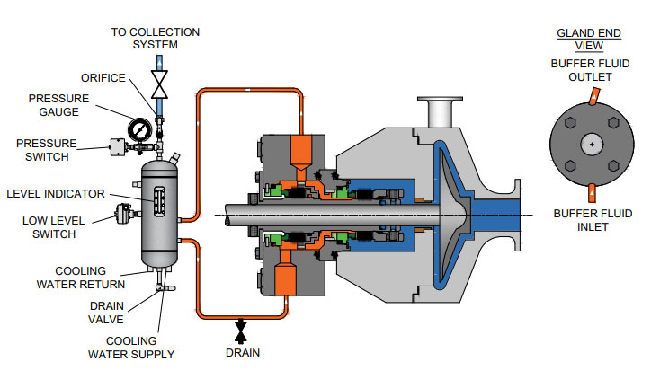
API Plan 52 takes buffer (unpressurized) fluid from a reservoir (seal pot), delivers it to the seal chamber, circulates it between the inboard and outboard seals using a pumping ring located driven by shaft rotation, then returns the fluid to the reservoir. In the event of an inboard seal failure, process fluid leaks into the seal chamber. When that occurs an increase in buffer fluid pressure and/or level alerts operators to the problem. The outboard seal, however, contains leakage until maintenance can replace the damaged seal.
This plan can include cooling coils in the reservoir to maintain the required buffer fluid temperature, visual or mechanical fluid level indicators, pressure and level transmitters, and connection to a collection system and buffer fluid replenishment source.
The overall design of this API plan for a double mechanical seal is relatively simple in comparison to other plans. Design decisions involving tubing size, length, geometry, type (carbon vs stainless steel), buffer fluid type, and volume of the buffer fluid reservoir are critical in maintaining the proper operating environment for the double seal. If you don’t have this expertise in-house, work with an experienced, local seal support system vendor to ensure the API Plan 52 is designed to meet your specific pumping requirements.
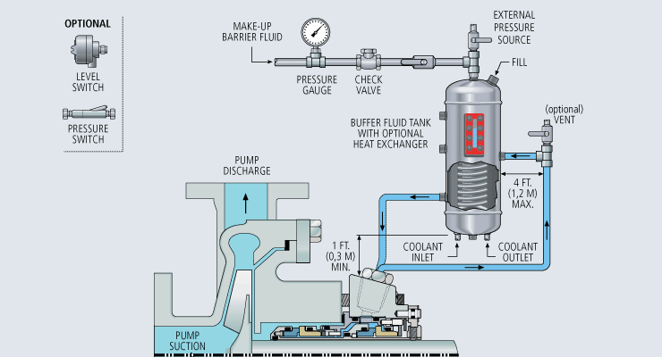
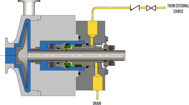
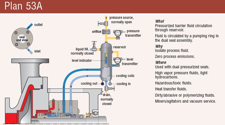
API Plan 53A is conceptually similar to API Plan 52 with the difference that the fluid being circulated between the double mechanical seals is under pressure. A pumping ring is used to circulate the fluid. The reservoir that contains the barrier fluid is pressurized by plant nitrogen. Reservoir pressure should be set a minimum of 20 to 25 psi (1.4 to 1.73 bar) above the maximum seal chamber pressure, allowing the barrier fluid to leak (and lubricate) across the inboard seal faces into the process fluid. For this reason, the barrier fluid must be chemically compatible with the process fluid.
Because barrier fluid is depleted as it moves across the inboard seal faces, it needs to be replenished. This can be done manually or automatically by way of a system that serves multiple pumps. API Plan 53A design options include reservoir type and volume, cooling coils, fluid level and pressure indicators, and transmitters to alert to level or pressure changes that indicate seal failure.
When you choose an API plan for a double mechanical seal, your primary decision is between a buffer or barrier plan. I’ve highlighted two of the API plans for double mechanical seals above to show the basic differences. There are multiple API plans for double mechanical seals to choose from—pressurization from bladder or piston accumulators, plant nitrogen delivered directly to the seal chamber, and custom-engineered external systems. Your choice will be determined by the process fluid and pumping conditions and the type of double mechanical seal your vendor recommends.
With this information in hand, it’s best to work with an experienced local seal support system vendor. They’ll be able to meet with you on-site to review the specifications for the pumping process, the pump, and the double mechanical seal. They’ll evaluate your existing infrastructure and its influence on seal support system design. Based on this information, they’ll then design the seal support system to meet the specific pumping requirements.
If you work with a global vendor like Swagelok, based on the design, we can quickly assemble and thoroughly test the API plan at our local facilities prior to delivery. We’re also conveniently available for follow-up consultations, on-site, remotely, or by way of a quick phone call.
For well over 50 years, Swagelok has worked closely with Northern California process industries to confidently choose the right API plans for pumping needs. Our locally based Field Engineers and certified technicians provide field verification of your seal support requirements, designs based on best practices gained from global experience.
To find out more about howSwagelok Northern California can help you choose the right API plan for double mechanical seals, as well as process and atmospheric side seals,contact our team today by calling
Morgan holds a B.S. in Mechanical Engineering from the University of California at Santa Barbara. He is certified in Section IX, Grab Sample Panel Configuration, and Mechanical Efficiency Program Specification (API 682). He is also well-versed in B31.3 Process Piping Code. Before joining Swagelok Northern California, he was a Manufacturing Engineer at Sierra Instruments, primarily focused on capillary thermal meters for the semiconductor industry (ASML).
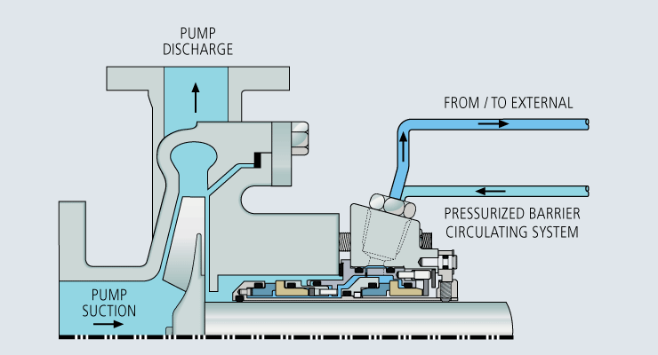
Pressurised barrier fluid circulation in outboard seal of dual seal configuration through a seal support system. Circulation is maintained by using pumping ring in running condition and with thermosyphon effect in stand still condition.
In Part 3 of our series on Double/Dual Mechanical Seals we take a look at the best piping plans/support systems to put in place to increase seal/equipment reliability and reduce energy/water costs.
More importantly, to extend the life of a double/dual seal, you want to control the fluid film that comes into contact with the primary seal faces to establish the ideal lubrication, temperature and pressure within the seal. Across all types of mechanical seal failures, inadequate/incorrect seal support systemsare the second highest cause of seal failures (Figure 1).
Standard environmental control plans (also called piping plans) have been developed for double/dual seals and choosing the right environmental control plan is critical to your seal performance and reliability.
This plan is used when working with hazardous process fluids in which no leakage into the product can be tolerated. It provides a backup seal in case of inboard seal failure.
If an inner seal leak is not detected early enough, the higher pressure process fluid will displace the buffer fluid. This can result in the process fluid completely filling the barrier fluid chamber between the inboard and outboard primary seals. Should the outer seal leak, product will be released into the atmosphere.
This plan is used in services where no product leakage into the atmosphere can be tolerated. Plan 53’s biggest advantage over Plan 54DM, which does not use a tank, is its limited fluid volume. The amount of fluid that can enter the product system is limited to the volume of the barrier fluid tank itself (usually 2-3 gallons or 8-12 liters).
Uses a pressurized external reservoir or barrier fluid tank to provide a clean, pressurized barrier fluid to both the inboard and outboard primary seals of a pressurized double/dual seal.
Leakage of barrier fluid into the product will always occur to some extent. Normally this leakage will be small and can be monitored by the barrier tank fluid level. Therefore, the chosen barrier fluid must always be compatible with the process fluid.
The tank pressure must be maintained at the proper level. If the barrier fluid tank pressure drops, the system will begin to operate like a Plan 52, or unpressurized dual seal, which does not provide the same level of sealing integrity. Specifically, the inner seal leakage direction will be reversed and the barrier fluid will, over time, become contaminated with the process fluid.
Directs a clean compatible fluid into and out of the dual mechanical seal barrier/buffer fluid ports. The purpose of this fluid is to prevent the pumped fluid from damaging the inboard seal faces, to remove heat from the seal, and to lubricate the outboard seal faces.
Careful consideration should be given to the reliability of the barrier fluid source. When the source is interrupted or contaminated, the resulting seal failures can be very costly.
The higher the differential pressure, the more transfer/migration into the product. The control should never be used where the barrier fluid pressure is likely to fall below seal chamber pressure. If this were to happen, the failure of one inboard seal from any mechanical seal in the system could contaminate the entire barrier fluid system with product and cause additional seal failures.
Once the inboard seal wears out or fails, the amount of barrier fluid that entered the product system is virtually unlimited unless it is shut down quickly. Alerting instruments should be put in place to avoid this.
Using appropriate monitoring devices, alarms, switches, etc. will provide a means to monitor the health of your double/dual seal to identify potential issues in advance avoiding costly unplanned outages. A basic Plan 52 buffer system will have a sight glass to monitor the buffer fluid level, a pressure gauge and connections to and from the mechanical seal, as well as a vent and drain valve. Cooling coils and level switches are typically available as optional items.
A Plan 53 would have the same features as the Plan 52 with the addition of a pressure regulator, safety valve, and an optional pressure switch. These systems can be customized to meet customer specifications should they desire to have additional features incorporated into the system.
For assistance with using the best seal support system for your specific challenge, ask your local Chesterton office or contact our Ask the Expert service.
Rules of Thumb for Mechanical Engineers assembles hundreds of shortcuts, calculations, practical "how-to" methods, and concise background reviews into one convenient volume.
Whether you"re concerned with design, selection, or performance, you"ll find fast, accurate answers here - all without wading through pages of theory.
Experts from all engineering disciplines have packed this book"s sixteen chapters with design criteria and practical tips. You"ll find easy-to-read descriptions on fluids, heat transfer, thermodynamics, seals, pumps, and compressors, drivers, gears, and bearings, as well as piping and pressure vessels.
The SO-1 buffer / barrier fluid reservoir is designed to contain barrier fluid for a tandem or double mechanical seal, to provide its cooling and to control mechanical seal performance. The SO-1 barrier fluid reservoir can be used with flush plans API 52 or 53 as per API682. To operate under the API 53 Plan, the barrier fluid tank can be equipped with a manual fluid make up pump.
The reservoir can be fitted with instrumentation and control for automatic checking of mechanical seal performance and pump shut down in case of mechanical seal failure. The instrumentation and control version of SO-1 can additionally include a level sensor, a pressure switch, and a temperature sensor. Sensors and switches are either intrinsically safe or explosion proof depending on customers order.
The rare feature of this buffer fluid reservoir is that it can be disassembled for cleaning if the heat exchanger gets fouled. The heat exchanger has straight tubes that can be mechanically cleaned.
John Crane understands that reliable seal performance is needed to maximize process efficiencies while meeting production constraints, and we know that dependable fluid control systems are required to support the performance you expect from our seals.
Regardless of the process fluid―from liquids to gases, cryogenic to boiling and abrasive to the purest finished product―our range of barrier fluid reservoirs, heat exchangers, abrasive separators and pump seal gas control panels support the complete spectrum of industrial processes. Ultimately, the seal"s performance is greatly influenced by the environment around the seal faces, making clean, cooled and filtered barrier fluid essential for mechanical seal performance and centrifugal pump-up time.
API 682, "Pumps ─ Shaft Sealing Systems for Centrifugal and Rotary Pumps," provides benchmark system solutions as well alternatives and customized solutions.
API Plan 54 is applicable to multiple, challenging applications in the oil and gas, chemical, pharmaceutical and other high purity industries. It is particularly flexible because it is a pressurized external lubrication system (PELS) designed to ensure that flow to the mechanical seal is not reliant on an internal circulation device, shaft speed or thermal siphon. This achieves a specific barrier fluid circulation rate and is ideal for high-reliability applications, such as high-purity and organics processes with elevated pressure or heat dissipation requirements.
Using best practice to inform operation, installation, reliability, maintenance and safety, John Crane introduced the GS 54, a new standardized Plan 54 support system designed to fit a wide range of challenging, dual pressurized seal applications. In tough and technically challenging processes where reliability is a prerequisite, the John Crane global standard API Plan 54 system is optimized to provide a standard solution across multiple industries, enabling avoidable complexity to be removed from the design and selection process.

Seal Support Systems operate to control the fluid in between and around the seal faces whether cleaning, cooling or heating the seal media or providing a separate fluid to the mechanical seal.
Some applications are simply not suitable for mechanical seals e. g applications which are corrosive, abrasive, crystallizing or precipitative. In order for a mechanical seal to operate under these applications with reasonable mean time between failure (MTBF), either the seal fluid requires treatment before coming into contact with the seal faces or an external fluid is required which is compatible with the process. Also double mechanical seals will require some sort of fluid to act as a buffer or barrier fluid andthe system which provides this buffer or barrier fluid are Seal Support Systems.
A seal plan is used in conjunction with the API 682 Standard and it is a way to formalise the different seal support systems into a standard. It consists of seal flush plans, buffer & barrier fluid plans, quench plans and gas supply plans.
The API Plan 53A is a dual seal plan where a barrier fluid is supplied to a double mechanical seal between the 2 sets of faces of the mechanical seal.
Plan 62 is a quench seal plan where a fluid is supplied to the space between the atmospheric side of the mechanical seal and the throttle bushing on the shaft.
Flowserve provides Seal Support Systems for in accordance with API 682 but can also provide systems outside of this standard, if the application dictates.
Our Mechanical Seal specialists can advise you on the appropriate selection of a seal support system which will deliver years of reliable service and operating cost savings in the longer term.

Plan 52 uses an external reservoir for providing buffer fluid for the outer seal of an unpressurised dual seal arrangement. Cooling coils in the reservoir are available for removing heat from the buffer fluid.
For Plan 53A, reservoir pressure is produced by a gas, usually nitrogen. A pumping ring maintains circulation during operation. Thermosiphon action is in effect during standstill. Reservoir size can be optimised in accordance with the flow rate. Any particles tend to settle at the bottom of the reservoir and don"t get recirculated. Similar to Plan 52, cooling coils are also used. Proper safeguards against the backflow of barrier fluid into the external supply of nitrogen also need to be considered.
Plan 53B makes use of an accumulator for isolating the pressurizing gas from the buffer fluid. A heat exchanger is also included in the loop in order to cool the fluid. It can either be water cooled, finned tubed, or air-cooled, depending on the system heat load.
Plan 54 employs an external source for providing a clean pressurised fluid. Plan 54 systems can be custom-made so as suit various application requirements and provide pressurised flow to various seal installations, thus keeping costs down.

A mechanical seal will run at its most stable condition when there is a sufficient pressure margin in the seal chamber over the process liquid’s vapor pressure at local temperature. The vapor pressure margin is defined as the difference between the absolute pressure in the seal chamber and the absolute vapor pressure of the pumped fluid. Flashing within the fluid film at the seal faces can be a major cause of seal dry running and premature seal failure. Cooling the process liquid to lower the vapor pressure is the API 682-preferred method of raising the vapor pressure margin, however, this is not always an option for some applications.
In lieu of cooling the liquid, which can be more cost-intensive or impractical for some services, the most used piping plans are those that act to remove the seal-generated heat while further raising the seal chamber pressure to achieve the desired vapor pressure margins. API 682 4th Edition standard states that the vapor pressure margin in the seal chamber shall be a minimum of 50 psi, or a minimum ratio of 1:3 between the absolute pressure in the seal chamber and the absolute vapor pressure of the pumped fluid at the pumping temperature if the 50 psi differential cannot be met. For face-generated heat, the API 682 recommendation is to flush the seal to limit a seal chamber temperature increase to less than 10°F.
While this subject has been extensively researched and documented this condensed discussion will only consider the most common flush plans used with mechanical seals. These plans can utilize the pressure distribution within the equipment to drive flow and manipulate the conditions local to the mechanical seal; in doing so, the environment can be made more favorable to long-term seal performance.
These plans do not rely on any supporting instrumentation or devices like a heat exchanger, but rather manipulate the pump and system’s pressure distribution as a mechanism to increase the vapor pressure margin. When considering the use of a mechanical seal piping plan, it is important to understand how specific pump arrangements can impact the seal chamber (and ultimately the performance of the mechanical seal) as the pressure and flow distribution will vary depending on several factors. These factors include but are not limited to:
It is important to note that an improperly selectedmechanical seal piping plan can be detrimental to seal performance in the same vein that a properly selected plan can improve seal performance.
The following mechanical seal piping plans service the inboard region of the seal – the region directly exposed to the process liquid. These piping plans are often employed to support single cartridge seals and/or unpressurized double cartridge seals where the seal faces will be relying on the process liquid for lubrication.
API 682 Plan 11, often the default API Plan for most single seals, is defined by its ability to prevent vaporization by maintaining positive pressure above vapor pressure. Additional features and characteristics include:
API 682 Plan 14 is a combination of Plan 11 and Plan 13 where process fluid is recirculated from the pump discharge through a control orifice, and from the seal chamber through a flow control orifice to the pump suction. Additional features and characteristics include:
The operating premise of these two piping plans is essentially the same – connect to a higher-pressure region of the pump to raise the local seal chamber pressure and introduce a flow to sweep away seal-generated heat. Through calculations relating to orifice dimensions, throat bushing clearances, pressure differentials, and expected face-generated heat, the desired seal environment can often be constructed from previously unfavorable conditions.
The point of focus in mechanical seal and seal support system design centers around managing the conditions of the very thin fluid film that supports the seal faces and prevents atmospheric escapes. Along with broad material compatibility and design requirements, the management of this fluid film is often the center of focus when reviewing a seal application, as the conditions within the seal chamber have a direct impact on the stability and consistency the mechanical seal faces experience.
There are certainly other piping plans and tactics that can help to manage seal chamber vapor pressure margins or fluid film stability within the seal. For further review, Flexaseal’s Piping Plan Guide includes a comprehensive breakdown of all defined piping plans and how they can impact the sealing environment.

www.chemicalprocessing.com is using a security service for protection against online attacks. An action has triggered the service and blocked your request.
Please try again in a few minutes. If the issue persist, please contact the site owner for further assistance. Reference ID IP Address Date and Time 5f57bddbf64db2565110a1cec4549334 63.210.148.230 03/03/2023 01:23 PM UTC


 8613371530291