
api plan for double mechanical seal quotation
Pumping processes involving toxic or hazardous fluids that can’t risk leakage because of stringent environmental regulations require a double mechanical seal. Compared to a single mechanical seal, a double seal gives you significantly greater protection against leaks. With a double mechanical seal, you have an arrangement of two mechanical seals (a primary or inboard seal and a secondary or outboard seal) in series—back-to-back, tandem, or face-to-face. Each seal has a rotating (R) surface and a stationary (S) seal surface. These seals can be arranged in one of three patterns.
In a back-to-back arrangement, the stationary seal faces are positioned back-to-back with the rotating seal faces on the outside. The back-to-back arrangement is easy to install and used for many general pumping applications.
The tandem arrangement has the two pairs of seals mounted with the same orientation. This arrangement is preferred for toxic or hazardous applications because the outboard seal provides full pressure back-up, allowing the outboard seal to back up in the event of an inboard seal failure.
In the face-to-face arrangement, the rotating seal faces share a common stationary seal face. This arrangement is useful when equipment space is too constrained to permit back-to-back or tandem seal arrangements.
The American Petroleum Institute (API) Standard 682 classifies double mechanical seals into two configurations—pressurized and unpressurized. The pressurized arrangement has a barrier fluid delivered to the double mechanical seal by a seal support system. The barrier fluid is delivered at a higher pressure than the process fluid and must be chemically compatible with the process fluid as it will lubricate the inboard seal faces and mix with the process fluid. The unpressurized arrangement has a buffer fluid delivered to the double mechanical seal by a seal support system. The buffer fluid is delivered at a lower pressure than the process fluid.
The barrier and buffer fluids you use can be liquid or gas. They provide lubrication and help maintain the required operating temperature of the seal faces. The typical choices are water and water/glycol mixtures, low-viscosity petroleum or synthetic oils, kerosene, diesel, and nitrogen.
To gain a better understanding of the differences between the uses of barrier and buffer fluids, let’s look at two common API plans for double mechanical seals—API Plan 52 Buffer Fluid Seal Pot and API Plan 53A Barrier Fluid Seal Pot Pressurized by Nitrogen.
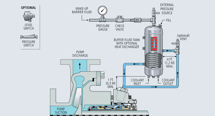
API Plan 52 takes buffer (unpressurized) fluid from a reservoir (seal pot), delivers it to the seal chamber, circulates it between the inboard and outboard seals using a pumping ring located driven by shaft rotation, then returns the fluid to the reservoir. In the event of an inboard seal failure, process fluid leaks into the seal chamber. When that occurs an increase in buffer fluid pressure and/or level alerts operators to the problem. The outboard seal, however, contains leakage until maintenance can replace the damaged seal.
This plan can include cooling coils in the reservoir to maintain the required buffer fluid temperature, visual or mechanical fluid level indicators, pressure and level transmitters, and connection to a collection system and buffer fluid replenishment source.
The overall design of this API plan for a double mechanical seal is relatively simple in comparison to other plans. Design decisions involving tubing size, length, geometry, type (carbon vs stainless steel), buffer fluid type, and volume of the buffer fluid reservoir are critical in maintaining the proper operating environment for the double seal. If you don’t have this expertise in-house, work with an experienced, local seal support system vendor to ensure the API Plan 52 is designed to meet your specific pumping requirements.
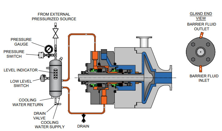
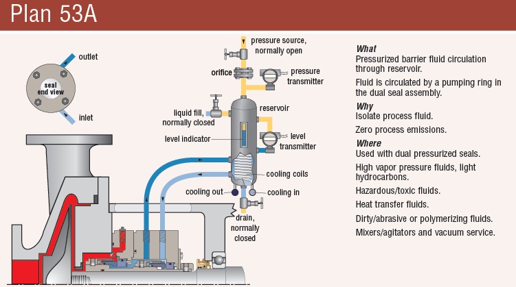
API Plan 53A is conceptually similar to API Plan 52 with the difference that the fluid being circulated between the double mechanical seals is under pressure. A pumping ring is used to circulate the fluid. The reservoir that contains the barrier fluid is pressurized by plant nitrogen. Reservoir pressure should be set a minimum of 20 to 25 psi (1.4 to 1.73 bar) above the maximum seal chamber pressure, allowing the barrier fluid to leak (and lubricate) across the inboard seal faces into the process fluid. For this reason, the barrier fluid must be chemically compatible with the process fluid.
Because barrier fluid is depleted as it moves across the inboard seal faces, it needs to be replenished. This can be done manually or automatically by way of a system that serves multiple pumps. API Plan 53A design options include reservoir type and volume, cooling coils, fluid level and pressure indicators, and transmitters to alert to level or pressure changes that indicate seal failure.
When you choose an API plan for a double mechanical seal, your primary decision is between a buffer or barrier plan. I’ve highlighted two of the API plans for double mechanical seals above to show the basic differences. There are multiple API plans for double mechanical seals to choose from—pressurization from bladder or piston accumulators, plant nitrogen delivered directly to the seal chamber, and custom-engineered external systems. Your choice will be determined by the process fluid and pumping conditions and the type of double mechanical seal your vendor recommends.
With this information in hand, it’s best to work with an experienced local seal support system vendor. They’ll be able to meet with you on-site to review the specifications for the pumping process, the pump, and the double mechanical seal. They’ll evaluate your existing infrastructure and its influence on seal support system design. Based on this information, they’ll then design the seal support system to meet the specific pumping requirements.
If you work with a global vendor like Swagelok, based on the design, we can quickly assemble and thoroughly test the API plan at our local facilities prior to delivery. We’re also conveniently available for follow-up consultations, on-site, remotely, or by way of a quick phone call.
For well over 50 years, Swagelok has worked closely with Northern California process industries to confidently choose the right API plans for pumping needs. Our locally based Field Engineers and certified technicians provide field verification of your seal support requirements, designs based on best practices gained from global experience.
To find out more about howSwagelok Northern California can help you choose the right API plan for double mechanical seals, as well as process and atmospheric side seals,contact our team today by calling
Morgan holds a B.S. in Mechanical Engineering from the University of California at Santa Barbara. He is certified in Section IX, Grab Sample Panel Configuration, and Mechanical Efficiency Program Specification (API 682). He is also well-versed in B31.3 Process Piping Code. Before joining Swagelok Northern California, he was a Manufacturing Engineer at Sierra Instruments, primarily focused on capillary thermal meters for the semiconductor industry (ASML).
Mechanical seal failure due to unfavorable operating conditions is an issue in every industry. Double mechanical seals especially require proper sealing accessories to create suitable operating environments which are key to increasing MTBF. Reservoir systems are one of the most common and effective options to supply cooling fluid crucial to successful seal operation.
A double -or dual – cartridge seal is defined as an arrangement of two mechanical seals in a series. These seals may be configured in various orientations within the cartridge. The seals themselves are referred to as the “primary” (or inboard) seal and the “secondary” (or outboard) seal. A double seal arrangement is the superior option to a single cartridge when it is imperative the product being pumped does not leak into the atmosphere. The API (American Petroleum Institute) Standard 682 classifies dual seals into two configurations. These configurations also apply to ASME (American Society of Engineers) B73.1 and ASME B73.2 pump designs.
Arrangement 2 (Unpressurized) Designs: the buffer fluid is the operating environment for the secondary seal and forms a “buffer” between the process fluid and the atmosphere.
Arrangement 3 (Pressurized) Designs: the barrier fluid is the operating environment for both the inboard and outboard seal, preventing process leakage to the atmosphere.
Buffer and barrier fluids may be either liquid or gas. These fluids lubricate seal faces during operation as well as regulate operating temperatures by moving heat—both generated and absorbed—away from the faces.
Seal support systems are necessary for the smooth operation of a dual mechanical seal. Here are two of the most common piping plans for these systems.
This is an unpressurized system consisting of a reservoir, supply and return lines, and an internal circulation device within the outer seal (commonly referred to as a pumping ring). The buffer fluid circulation rate is dependent on how this circulation device functions during seal operation.
Reservoirs may be fitted with a variety of measurement devices such as a liquid level indicator and pressure gauges as well as valves and switches to aid in various operation and maintenance functions. For instance, a typical support system configuration for natural gas liquids (NGL) would issue an alarm (visual, audible, or both) when the inner seal fails. In addition, the outer seal would take over the primary seal function until maintenance is performed.
This system forces gas from an external pressurized source into the reservoir to pressurize the barrier fluid. This means the reservoir pressure will be above seal chamber pressure; a guideline is a minimum of 20 to 25 psig (1.4 to 1.73 bar) above the maximum process pressure.
The Plan 53A is also used to maintain a specific operating temperature range to ensure optimum lubrication at the seal faces. The reservoir houses a cooling coil which actively cools the barrier fluid as necessary.
As with the Plan 52, a circulation device is used to move the barrier fluid. Replenishing a Plan 53A system with fresh barrier fluid can be as simple as a using a hand pump or a more complex arrangement which satisfies multiple seals.
& 5. Fuels such as diesel or kerosene, and alcohol solutions may also we used, but it is imperative that these fuels be evaluated for safety and compatibility before put into service.
Liquid-lubricated dual mechanical seals require an external source of clean, cool lubricating fluid. The following fluid reservoir systems create this enhanced sealing environment, enabling longer operational life for dual seals.
In the oil and gas industry, reliable seal operation is critical to running efficient, safe processes. In conjunction with API 682 Piping Plans 52 and 53A, seal support systems aid in smooth seal operation.
If you require an engineered seal support system or are interested in additional options to Flexaseal’s ANSI PLUS and ANSI LITE support systems, please contact our applications engineering team.
To keep mechanical seal systems functioning as long as possible, we recommend using standardized seal piping plans. Detailed API seal piping plans ensure minimal seal face wear by maintaining the optimal seal chamber environment.
Since they were first formulated, seal piping plans have been maintained and remodeled by the American Petroleum Institute (API). Current plans are based on API 682 and are sorted numerically. In some cases, designated letters are also used to differentiate between plans.
-1.png?width\u003d360\u0026name\u003dimage2%20(3)-1.png)
Used to detect and monitor leakage of the inboard seal, these seal support systems can detect liquid leakage (API Plans 65 and 75) or gas leakage (API Plan 76), or a mixture of gas and liquid leakage (API Plan 75). A PD 76 (API Plan 76) system diverts non-condensing inner seal leakage from a dual unpressurized seal where the outer seal is dry running, to a flare or vapor recovery system.

In Part 3 of our series on Double/Dual Mechanical Seals we take a look at the best piping plans/support systems to put in place to increase seal/equipment reliability and reduce energy/water costs.
More importantly, to extend the life of a double/dual seal, you want to control the fluid film that comes into contact with the primary seal faces to establish the ideal lubrication, temperature and pressure within the seal. Across all types of mechanical seal failures, inadequate/incorrect seal support systemsare the second highest cause of seal failures (Figure 1).
Standard environmental control plans (also called piping plans) have been developed for double/dual seals and choosing the right environmental control plan is critical to your seal performance and reliability.
This plan is used when working with hazardous process fluids in which no leakage into the product can be tolerated. It provides a backup seal in case of inboard seal failure.
If an inner seal leak is not detected early enough, the higher pressure process fluid will displace the buffer fluid. This can result in the process fluid completely filling the barrier fluid chamber between the inboard and outboard primary seals. Should the outer seal leak, product will be released into the atmosphere.
This plan is used in services where no product leakage into the atmosphere can be tolerated. Plan 53’s biggest advantage over Plan 54DM, which does not use a tank, is its limited fluid volume. The amount of fluid that can enter the product system is limited to the volume of the barrier fluid tank itself (usually 2-3 gallons or 8-12 liters).
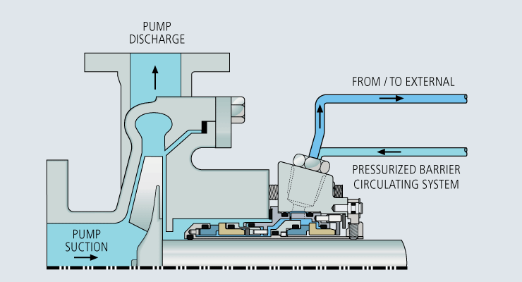
Uses a pressurized external reservoir or barrier fluid tank to provide a clean, pressurized barrier fluid to both the inboard and outboard primary seals of a pressurized double/dual seal.
Leakage of barrier fluid into the product will always occur to some extent. Normally this leakage will be small and can be monitored by the barrier tank fluid level. Therefore, the chosen barrier fluid must always be compatible with the process fluid.
The tank pressure must be maintained at the proper level. If the barrier fluid tank pressure drops, the system will begin to operate like a Plan 52, or unpressurized dual seal, which does not provide the same level of sealing integrity. Specifically, the inner seal leakage direction will be reversed and the barrier fluid will, over time, become contaminated with the process fluid.
Directs a clean compatible fluid into and out of the dual mechanical seal barrier/buffer fluid ports. The purpose of this fluid is to prevent the pumped fluid from damaging the inboard seal faces, to remove heat from the seal, and to lubricate the outboard seal faces.
Careful consideration should be given to the reliability of the barrier fluid source. When the source is interrupted or contaminated, the resulting seal failures can be very costly.
The higher the differential pressure, the more transfer/migration into the product. The control should never be used where the barrier fluid pressure is likely to fall below seal chamber pressure. If this were to happen, the failure of one inboard seal from any mechanical seal in the system could contaminate the entire barrier fluid system with product and cause additional seal failures.
Once the inboard seal wears out or fails, the amount of barrier fluid that entered the product system is virtually unlimited unless it is shut down quickly. Alerting instruments should be put in place to avoid this.
Using appropriate monitoring devices, alarms, switches, etc. will provide a means to monitor the health of your double/dual seal to identify potential issues in advance avoiding costly unplanned outages. A basic Plan 52 buffer system will have a sight glass to monitor the buffer fluid level, a pressure gauge and connections to and from the mechanical seal, as well as a vent and drain valve. Cooling coils and level switches are typically available as optional items.
A Plan 53 would have the same features as the Plan 52 with the addition of a pressure regulator, safety valve, and an optional pressure switch. These systems can be customized to meet customer specifications should they desire to have additional features incorporated into the system.
For assistance with using the best seal support system for your specific challenge, ask your local Chesterton office or contact our Ask the Expert service.

When discussing slurry pump seal support plans it seems that the terms “Flush” and “Quench” are often confused and or misused. With the concept being slightly different for mechanical seal boxes vs packed seal boxes I will separate these, discussing each in turn.
The basic mechanical seal flush plan is very simple. It calls for a clear/clean liquid, usually water, to be introduced into the space between the actual seal and an impeller side exit restriction. The flush liquid is introduced at a pressure above that of the pumpage, thus assuring a positive outward flow/flush and a clean operating environment for the mechanical seal. This is illustrated below.
The definition of a flush is a “fluid which is introduced into the seal chamber on the process fluid side in close proximity to the seal faces and typically used for cooling and lubricating the seal faces.
When flushing is required, Toyo recommends the use of an API plan 32 seal piping arrangement as it is better suited in services containing solids or contaminants which could damage the seal faces if recirculated in the flush media.
The Plan 32 typically uses a clear clean fluid supplied from an external source delivered to the primary seal faces on the process fluid side of the seal. With the use of a close-clearance throat bushing, the stuffing box can be back pressured to an elevated pressure ensuring the flushing fluid will not flash across the seal faces.
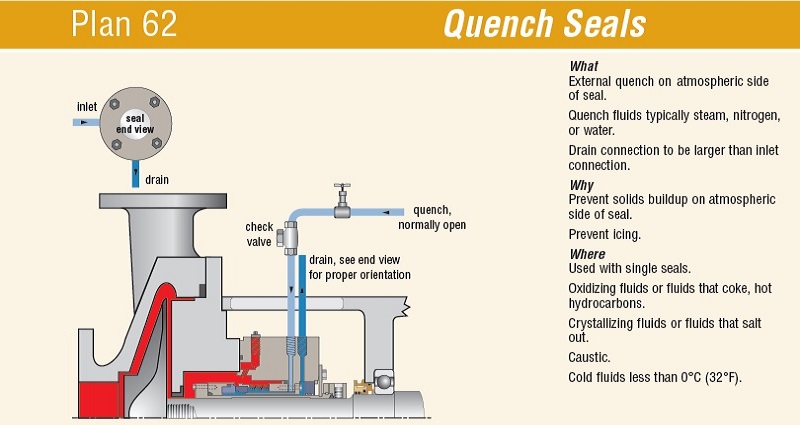
A quench plan, as the name indicates, is designed to quench or cool the seal. It is normally used if short periods of dry running are expected. As illustrated bellow, the fluid is introduced into the area between the back of the seal faces and the close fit exit on the drive side of the pump.
API 682 3rd Edition defines a quench as a“neutral fluid, usually water or steam, is introduced on the atmospheric side of the seal to retard formation of solids that may interfere with movement, or for other purposes.”
Some quench seal plans replace the close fit exit restriction with a secondary seal and a top exiting port that can be plumbed to capture the spent quench fluid and route it away from the rotating assembly. The principal is however just the same, we are trying to cool the seal not in any way flush the seal.
The primary goal of all flush water plans is to preclude the pumpage from contaminating the seals. As such flush water plans for packed boxes are very similar to that of mechanical seal boxes. However, as illustrated below there are some obvious mechanical differences. The most striking difference is the addition of a seal (packing) located between the injection port and the exit restriction. This minimizes the volume of flush liquid consumed.
From an operational standpoint, the packed box differs as it requires some leakage to assure lubrication and prevent heat build-up. The mechanical seal box should have no leakage.
When working with a packed box, whether it be a flush, the rule of thumb for setting water pressure is the same. The pump shut off pressure, plus 10% or plus 20 psi, which ever is greater. There is however a difference in how flow rates are set.
With a standard flush plan, flow is typically adjusted by compressing the packing until a few drops are observed leaking out of the seal on the drive side. On a quench plan, flow rate is set by adjusting an inlet valve while at the same time using a valve on the exhaust side to maintain the correct seal box pressure. If the exit water from the seal box is too hot, flow rate is increased until exit water is cool while still maintaining the proper seal box pressure.
I hope this short blog helps clear up some of the confusion with seal flush plans. Before signing off for today, let me confirm the information provided today is general info only. Always refer to the pump manuals for specific details. If still in doubt, our applications team here at Toyo is always willing to support you in any way they can.
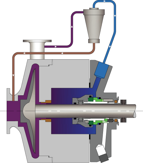
Cyclone separators are typically used in an API Plan 31 arrangement and incorporated in the seal flush line (API Plan 11 ) from the discharge of the pump.
53B accumulator-based seal support systems utilize a bladder to maintain system pressure to pressurized dual seals and absorb barrier fluid thermal expansion while separating the pressurizing gas and barrier fluid.
53C accumulator-based seal support systems utilize a piston to maintain system pressure to pressurized dual seals and absorb barrier fluid thermal expansion while separating the pressurizing gas and barrier fluid.
Used to detect and monitor leakage of the inboard seal, these seal support systems can detect liquid leakage (API Plans 65 and 75) or gas leakage (API Plan 76), or a mixture of gas and liquid leakage (API Plan 75).
Used to detect and monitor leakage of the inboard seal, these seal support systems can detect liquid leakage (API Plans 65 and 75) or gas leakage (API Plan 76), or a mixture of gas and liquid leakage (API Plan 75).
Used to detect and monitor leakage of the inboard seal, these seal support systems can detect liquid leakage (API Plans 65 and 75) or gas leakage (API Plan 76), or a mixture of gas and liquid leakage (API Plan 75).
A PG 72 (API Plan 72) system is used to provide a clean, regulated gas supply to a dual unpressurized seal arrangement where the containment seal is dry running.
A PG 74 (API Plan 74) system provides a clean, dry, regulated supply of pressurized barrier gas (usually nitrogen) to dual pressurized, non-contacting seals.
These reservoir-based seal support systems are designed for both API Plan 52 and 53A applications to support unpressurized and pressurized dual seals.
Plant seal water filtration system, maintaining clean water supply to improve the reliability mechanical seals and gland packing and also flow control and pressure-regulating devices.
SafeJet is an automatic seal water filter. Its operation is based on “flow-through” filter technology, which utilizes reliable laminar filtering method.
Water-cooled heat exchangers may be applied where water is readily available. Heat exchangers may be packaged together with seal support systems when additional cooling is required.
Water-cooled heat exchangers may be applied where water is readily available. Heat exchangers may be packaged together with seal support systems when additional cooling is required.
Most centrifugal compressors today use dry gas seals to contain high-pressure gas, whether on a high-pressure reinjection duty or a low-pressure pipeline machine.
IIndufil® ball valves are designed in-house and manufactured for use in duplex systems to enable continuous operation while one side of a system receives maintenance.
Pressurised barrier fluid circulation in outboard seal of dual seal configuration through a seal support system. Circulation is maintained by using pumping ring in running condition and with thermosyphon effect in stand still condition.
When a customer’s system was continually clogging due to the outside flush source, one of our distributors contacted FSI to review the application. Our distributor’s end-user was in need of a solution and wanted to get away from using their existing API Plan 32. An API Plan 32 delivers a clean flush fluid into the seal chamber from an external source.
FSI recommended our newly designed and state-of-the-art 1040 EQ seal. The 1040 EQ makes your single seal act like a double seal. In addition, the 1040 EQ:
By using the 1040 EQ, FSI was able to eliminate the outside water source (API Plan 32) by replacing it with our self-lubricating system that is incorporated into the seal port. In addition, the 1040 EQ has a design feature with a pumping scroll which lowers the stuffing box pressure and allows the seal to run on the fluid supplied by the luber.
The 1040 EQ is so effective, that it can replace a double cartridge seal and seal pot. For more information on the 1040 EQ seal, contact FSI today at 412-865-2101.

Flexaseal offers replacement seals for a full array of compressors, mixers, pumps, and other rotating equipment. Direct replacements are available in standard inch and metric sizes and materials for major brands, including
With four (4) configuration options all incorporating additional engineered features such as reverse pressure capability, non-clogging multi-springs, rugged seal drive operation, and hydraulically balanced faces, the RKCS single and RKCD dual seals successfully contend with the industry’s toughest slurry challenges.
Flexaseal provides component seals for a wide range of challenging applications where cartridge seals are impractical or incompatible with current rotating equipment. This may be due to equipment not having a seal chamber or the seal need to be installed on the wet side of a pump. We offer a sturdy single spring component seals, externally mounted mechanical seals for extremely corrosive applications, and stationary seats (mating rings).
There is no one universal seal for all mixer applications. Every mixer, agitator, and reactor model is distinctive and engineered for a specific application. Many of these applications require seals to perform in environments that would destroy common seals due to extreme drag and shear forces, abrasive materials, or other challenges. That means successful sealing requires clearly defining the type of equipment, the product, and the sealing conditions. Flexaseal’s design and engineer team are capable of providing innovative solutions for your toughest challenges.
The mechanical seal style GFR/GFL offers a number of benefits over liquid lubricated dual seal for API plans 53 and 54. These include lower maintenance costs for the seal and support system since there is no barrier fluid to fill and the ability to retain 100% product purity through the use of nitrogen as a lubricant.
The resultant gas film pressure provides an opening force slightly greater than the net closing forces, which cause the faces to separate and not contact.
Simple support system – utilizes API 682 Plan 74 instead of more complex Plans 53 or 54, lowering the cost of operation and maintenance of the seal support system
Viscous substances such as syrups, tars, thick oils, resins, and glues prove to be challenging for most mechanical seals. Lip seal designs have been the go-to option for these processes that have centipoise values well above the normal range for seal face operation. The MLC3 cartridge seal achieves optimum pumping rates at lower speeds with fewer sealing issues than products currently in the field and requires virtually no seal support system.
Machined lip seals with deflected lip geometry ensures reliable sealing while producing a smaller footprint compared to competitor designs. This smaller footprint reduces parasitic torque and heat generation.
Single Lip Seal with anti-rotation ring and integrated back up ring: Energized front lip prevents leakage when transitioning between high viscosity and high fluidity processes. Anti-rotation rings statically seal even under normal temperature cycling. The integral back up ring provides added lip support under higher pressures and potential pressure spikes.
Double Lip Seal with anti-rotation ring: The PTFE-ML compound is formulated with a lower coefficient of friction, which coupled with the enhanced heat dissipation leads to lower under-lip temperatures. Lower temps = lower seal and sleeve surface wear.
Lantern Ring: Multifunctional PTFE ring provides additional bearing support as well as even dispersion of lubricant or barrier/buffer fluid around the lip seals.
Energized O-ring front lip tolerates lower speeds and higher shaft runout. This design increases sealing viability with certain emulsifiers and fluid viscosity transitioning such as CIP applications.
Sleeve: Sintered Silicon Carbide sleeve for durable wear and sealing surface. Inboard and outboard sleeve O-rings dampen vibration and aid in easy removal and repair.

try to play around with the hydrostatic pressure. slowly reduce the pressure by adjusting the nitrogen purge pressure and at the same time consistently try to hand rotate the pump. if the jamming is loosening as you gradually reduce the pressure, then it is indeed the jamming is due to this 5 bar. Hence this 5 bar is literally pushing the rotating face onto statinonary face until you are not able to rotate it manually. good that you try to rotate it before starting it. If you start the pump with this 5 bar, you could have end up with significant wear on the seal faces.
i do not know whether this behavior is anticipated or not. as long as the seal pot level is not going down at stop, i know the seal is fit for operation. if it require reduction (not total release) in the hydrostatic pressure prior starting up, so be it. you can always increase the pressure if the pot level is increasing after that. if it is holding, you can decide to maintain the reduced pressure
Seal Support Systems operate to control the fluid in between and around the seal faces whether cleaning, cooling or heating the seal media or providing a separate fluid to the mechanical seal.
Some applications are simply not suitable for mechanical seals e. g applications which are corrosive, abrasive, crystallizing or precipitative. In order for a mechanical seal to operate under these applications with reasonable mean time between failure (MTBF), either the seal fluid requires treatment before coming into contact with the seal faces or an external fluid is required which is compatible with the process. Also double mechanical seals will require some sort of fluid to act as a buffer or barrier fluid andthe system which provides this buffer or barrier fluid are Seal Support Systems.
A seal plan is used in conjunction with the API 682 Standard and it is a way to formalise the different seal support systems into a standard. It consists of seal flush plans, buffer & barrier fluid plans, quench plans and gas supply plans.
The API Plan 53A is a dual seal plan where a barrier fluid is supplied to a double mechanical seal between the 2 sets of faces of the mechanical seal.
Plan 62 is a quench seal plan where a fluid is supplied to the space between the atmospheric side of the mechanical seal and the throttle bushing on the shaft.
Flowserve provides Seal Support Systems for in accordance with API 682 but can also provide systems outside of this standard, if the application dictates.
Our Mechanical Seal specialists can advise you on the appropriate selection of a seal support system which will deliver years of reliable service and operating cost savings in the longer term.

Double seal, compact design, balanced, independent from the direction of rotation, multi-spring. The seal requires application of buffer or barrier liquid installation.
The BED is a general purpose mechanical seal with a wide range of applications. It is designed to work with media containing abrasive particles (e.g., ash, ores, cement, sludge and suspended matter) and chemicals harmful to the environment.
BED seal requires installation of a system of buffer liquid (acc. to API Plan 52, 55) or barrier liquid (API Plan 53a, 53b, 53c, 54). Maximum pressure of barrier liquid: 2.0 MPa.


 8613371530291