
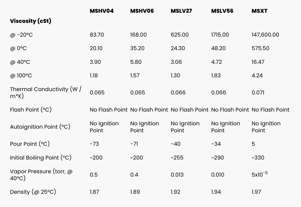
barrier fluid for mechanical seal pricelist

This website is using a security service to protect itself from online attacks. The action you just performed triggered the security solution. There are several actions that could trigger this block including submitting a certain word or phrase, a SQL command or malformed data.

DuraClear Crystal 7 Seal Lubricant is a premium barrier fluid for use on equipment handling high purity, high value or highly reactive product fluids such as strong acids and bases. It has been specifically formulated for the lubrication needs of dual mechanical seals. When chemical compatibility is critical, this environmentally friendly and nonreactive barrier fluid extends the life of dual mechanical seals for increased process yield and throughput.
CTFE fluids may react violently with K, Na, amine, hydrazine, liquid fluorine, liquid chlorine trifluoride, Aluminum, Aluminum Chloride (AlCl3) and Aluminum Oxide (Al2O3)
Multiple mechanical seal failures in a crude distillation unit (CDU) resulted in total losses of $3 MM in a refinery since its startup in January 2015. The maximum seal life achieved did not exceed 6 mos, which was much shorter than the American Petroleum Institute (API) 682 “Advancements in Mechanical Sealing” goal of 3 yr of seal life.
Multiple mechanical seal failures in a crude distillation unit (CDU) resulted in total losses of $3 MM in a refinery since its startup in January 2015. The maximum seal life achieved did not exceed 6 mos, which was much shorter than the American Petroleum Institute (API) 682 “Advancements in Mechanical Sealing” goal of 3 yr of seal life.
The root causes of failure for the mechanical seals for 16 hot hydrocarbon service pumps (with operating temperatures in excess of 250°C) are discussed here, and solutions are demonstrated to eliminate failures and improve plant reliability.
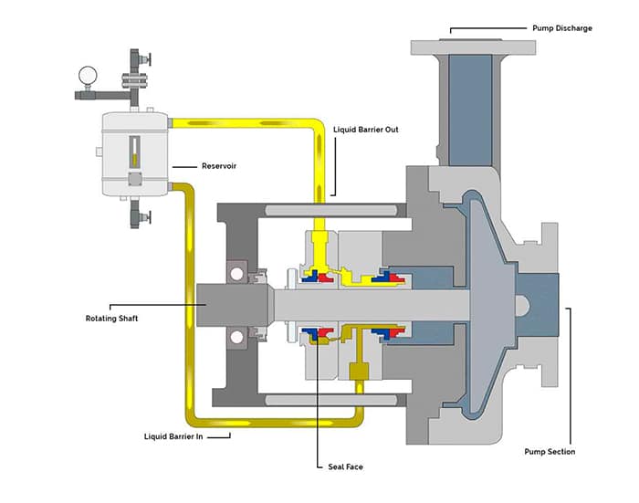
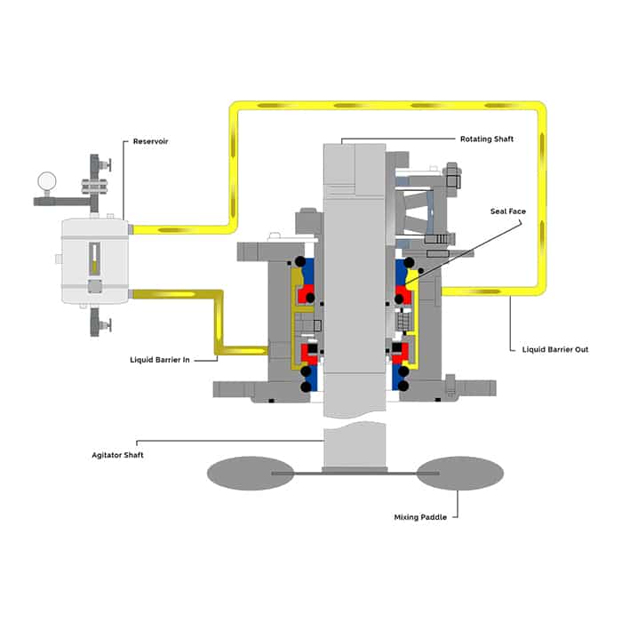
CDU hot pumps are equipped with API seal flushing Plan 32 (injection to seal chamber from an external source) and API seal flushing Plan 54 (pressurized external barrier fluid). API Plan 32 utilizes heavy vacuum gasoil (HVGO) that is supplied at 1.7 barg above the seal chamber pressure at 110°C. API Plan 54 utilizes light vacuum gasoil (LVGO) that is supplied at 1.7 barg greater than that of Plan 32 pressure at 110°C. For example, if the seal chamber pressure is 5 barg, Plan 32 should be supplied at 6.7 barg (5 + 1.7), and Plan 54 should be at 8.4 barg (6.7 + 1.7).
The flowrate for each API plan varies, depending on the pump service. The HVGO utilized for Plan 32 is produced from the CDU and supplied to the CDU hot pumps by a common system, as shown in FIG. 1. The LVGO utilized for Plan 54 is produced from the CDU and supplied to the CDU hot pumps by a common closed system (FIG. 2).
Mechanical seal failure data was collected from a computerized maintenance management system (CMSS), and selection criteria were set to concentrate the focus on the “bad actor” pumps. Selection criteria included an operating temperature that exceeded 250°C. The seal failure history is indicated in TABLE 1, which shows a total of 41 seal failures that occurred in 2015 vs. 25 failures in 2016. The large discrepancy in failures between 2015 and 2016 was due to a startup and commissioning period in early 2015, during which time the refinery was suffering from system dirt, operational upsets and various commissioning problems. While seal failures were reduced in 2016, equipment mean time between failure (MTBF) and seal life were unsatisfactory for refinery maintenance key performance indicators (KPIs) and targets.
A root cause analysis (RCA) was conducted in April 2016 to identify the root cause of failure for CDU bad actor pumps to eliminate seal failures and enhance equipment reliability. This RCA evaluated all possible seal failure causes including, but not limited to, the following major possible causes:
Almost 90% of the dismantled failed mechanical seals experienced either coke formation or sludge in the outboard seal side (secondary seal provided with Plan 54 barrier fluid). Most of the findings showed coke particles trapped on the rotating face along the outboard seal side and bellows, as shown in FIGS. 3 and 4.
Figs. 3 and 4. Almost 90% of the dismantled failed mechanical seals experienced either coke formation or sludge in the outboard seal side and bellows.
The RCA team also reviewed the design basis and barrier fluid (API Plan 54) selection criteria. It was concluded that LVGO is not a compatible seal barrier fluid, as the most desirable viscosity range for any hydrocarbon seal barrier is between 2 cSt and 10 cSt in accordance with API 682 (shaft sealing systems for centrifugal and rotary pumps). To achieve this viscosity range, the operating temperature for the LVGO was increased during the design phase of the refinery to 110°C, which contradicts the refinery standard that limits the barrier fluid for Plan 54 to a temperature of 70°C.
In addition, barrier fluid selection was reviewed for other process units within the refinery that contain pumps with similar operating parameters and that utilize API seal Plan 32 and Plan 54, such as hydrocracking (HCK) units and delayed coker units (DCUs). Similar pumps within HCK units utilize diesel for both API plans at 50°C–60°C, whereas DCU pumps utilize heavy coker gasoil (HCGO) at 60°C and light coker gasoil (LCGO) at 60°C for Plan 32 and Plan 54, respectively. Seal failures for both units, along with failures modes, were also evaluated and were found to be satisfactory.
The RCA concluded that the direct cause of the mechanical seal failures was due to coke formation in the outboard seal (atmospheric side), which impacted the seal bellows and caused the seal faces to open. It was also concluded that the root cause of failure was due to the improper selection of API seal Plan 54 (LVGO), as this type of hydrocarbon has been proven to form coke at 110°C on the atmospheric side of the seal.
The effect of coke formation in mechanical seals can be understood from a mechanical seal balance ratio. Mechanical seal vendors design the seal face with a balance ratio to minimize heat generation between seal faces. This seal ratio also impacts seal faces opening and closing forces. The seal balance ratio normally ranges from 0.6–0.9.
When coke forms and solidifies on the seal faces, the seal outer diameter will increase, resulting in a higher opening force that, in turn, leads to excessive leakage, as shown in FIGS. 5 and 6.
The RCA recommended changing the barrier fluid from LVGO to diesel (supplied from the CDU atmospheric column). The API seal Plan 54 common pumps (FIG. 2) were evaluated to accommodate this change, and it was found that diesel was unsuitable for these pumps at high temperatures—the pumps were designed for LVGO, which has a relatively higher viscosity than diesel. To overcome this problem, it was decided to cool the diesel to 50°C to increase fluid viscosity.
After the refinery turnaround, the CDU bad actor pumps were monitored closely for 13 mos following the refinery startup in December 2016. Seal failures were determined to be almost entirely eliminated, and seal life was increased. TABLE 2 shows the total number of seal failures since diesel was utilized with API Plan 54. The number of failures was reduced drastically to two, compared to the same period in 2016. For example, pump 110-G-0016 C (which was considered as the most troublesome CDU bad actor pump) had zero failures compared to eight failures since the refinery startup. Although some failures were recorded since diesel was utilized as barrier fluid, it is strongly believed that these failures were due to remaining LVGO traces in the seal internals.
In addition, the RCA identified areas of improvement with regard to quality assurance and quality control procedures, which had been found to be less than adequate. The RCA team developed mechanical seal replacement procedures that focused on improving the following important aspects in accordance with API 686 “Recommended Practices for Machinery Installation” and equipment OEM manuals:
Ahmed A. Telmesani is a Maintenance Engineer for Yanbu Saudi Aramco Sinopec Refinery (YASREF). His responsibilities and areas of focus include eliminating failures, enhancing systems reliability, power saving initiatives, early failure detection and continuous preventive maintenance review and enhancement. He previously spent 10 yr with Saudi Aramco. Mr. Telmesani earned his BS degree in mechanical engineering from King Fahad University of Petroleum and Minerals (KFUPM) in Dhahran, Saudi Arabia.
Lubriplate Barrier Fluids are ultra-clean, polyalphaolefin (PAO) synthetic based fluids recommended for all types of mecahnical seals. While they are NSF H1 registered food grade, they may be used for all applications requiring barrier fluid for mechanical seals.
Chesterton Mechanical Seal Chesterton® Mechanical Seal Support Systems are designed to optimize the seal’s operating environment in order to increase its reliability and Mean Time Between Repair (MTBR). The fluid film on which the seal operates is critical to its life expectancy; slurries, hot liquids, crystallizing solutions, and high viscosity and solidifying media often require adequately specified seal support systems in order for the mechanical seal to function correctly. Selecting the correct support system is crucial. The seal and equipment on which the seal support system is being...
Support Systems Single Seals Single seals operating in harsh processes are most commonly configured to seal flush systems such as Plan 32, Plan 33, or variants thereof, utilizing plant water supplies as a source of clean, cool flush. The plant water line is often connected directly to the seal or stuffing box chamber without adequate controls. Excessive water consumption and/or accidental loss of flush can result in premature failure. Our Flow Guardian™ provides control and indication of flush supply to ensure the mechanical seal is operating in its optimum environment. Seal Tank Systems...
WSS Water Saving System Plan 53P Automatic Water Support Tank Easy to install, complete solution with minimal water consumption for reliable operation of dual mechanical seals. The Chesterton Water Saving System (WSS) is a complete seal support system designed to maintain water barrier pressure and levels without maintenance. Containing all of the equipment required for connection to a dual mechanical seal, the Water Saving System is easy to install. Water Saving System Configuration Featuring a pressure regulator, non-return valve, and vent valve, the Water Saving System isolates the dual...
Operating Principle Water from the plant water line enters the system through the non-return valve. The pressure of the barrier fluid in the tank can be set via the pressure regulator. 3 Flow Indicator 4 Vent Valve Once at the correct pressure, the plant water line remains connected to automatically top up and maintain the pressure. Water consumption is minimal. (Water Line Connection) B To the Mechanical Seal C From the Mechanical Seal 6 Mounting Brackets 7 3-Way Valve 8 Drain Valve The barrier fluid is circulated to the seal and back to the system by the thermosyphon effect. Ordering...
BSS Buffer Support System Plan 52 Non-Pressurized Tank Easy to install, complete non-pressurized solution for reliable operation of dual mechanical seals. The Chesterton Buffer Support System (BSS) for dual mechanical seals is a complete solution for the environmental support of dual mechanical seals where product contamination from support fluid cannot be tolerated. BSS Configuration Supplied ready to install the BSS is preconfigured to allow simple connection and non-pressurized support to a dual mechanical seal. A dedicated fill valve allows quick and easy commissioning of the seal and...
Operating Principle The support fluid is circulated by thermosyphon effect or the mechanical seal’s pumping ring. Connect the system to the seal and add the support fluid via the fill valve until it is at the required level on the glass. 4 Drain Valve 5 Auxiliary Connections Ordering Codes Type Item Number Buffer Support System complete with all the Components Buffer Support System complete with Cooling Coil Tank Stands Telescopic Vertically and Horizontally Adjustable Stand - Stainless Steel Piping Kits Fixed Stand - Stainless Steel Telescopic Vertically and Horizontally Adjustable Stand -...
PSS Pressurized Support System Plan 53A Standard Tank Easy to install, complete pressurized solution, for reliable operation of dual mechanical seals. The Chesterton Pressurized Support System (PSS) for dual mechanical seals is a complete solution for the support of dual mechanical seals where product leakage cannot be tolerated. Pressurized Support System Configuration Supplied ready to install, the PSS features a non-return valve, pressure regulator with gauge, and pressure relief valve. A dedicated fill valve allows quick and easy commissioning of the seal and system arrangement. The PSS...
Operating Principle Close the fill valve and connect the air or nitrogen supply and adjust the regulator to the required pressure. Connect the system to the seal and add the support fluid via the fill valve until it is at the required level on the glass. The barrier fluid is circulated by thermosyphon effect or the mechanical seal’s pumping ring. Mounting Brackets Ordering Codes Type Item Number Pressurized Support System complete with the Components Pressurized Support System complete with Cooling Coil Fixed Stand - Stainless Steel Telescopic Vertically and Horizontally Adjustable Stand -...
Flow Guardian Plan 32/33S/54DM Specifically designed to supply uninterrupted, regulated seal flush water and deliver operational efficiency to the pump population. Managing flow rates while regulating important pressure differentials is possible. Costly seal failures are reduced while assisting in-plant water conservation initiatives. Flow Guardian Selection There is a Flow Guardian for every application. The DP50 Dual Flow Guardian is designed to measure flow entering and exiting a dual seal installation. This capability allows for early detection of leakage into the process stream as a...
Water Saver Features a thermally activated valve that automatically drains hot barrier fluid (only when necessary) to keep dual seals running cool and reliable. Valve opening temperature preset to work with S20 Seals. 95% water savings compared to open barrier fluid supply Recommended Applications Technical Data Chemical industry Pulp and paper industry Operating Parameters Pressure Limit Temperature Limit Temperature Set Point Connections 20.7 bar g / 300 psig* 125°C / 257°F 80°C / 176°F 1/4" NPT Materials of Construction Body Bushing Hose Barb Fitting 303 Stainless Steel / EN 1.4305 316...
FSI Series 1015 mechanical cartridge seals are a premium grade product without the premium price. They"re ideal for use with most ANSI and DIN (standard and big bore) pumps and other types of pumps and rotating equipment. They have the following features:
Strong rely on the people to carry out intrinsic funds burden that mechanical seal selection, quotation, engineering design, manufacturing, service and all processes of technical guarantee caused by providing a kind of automated system to be solved, this system supports these operations at each aspect different, and do not need the senior training of many processes people or sales engineer, producer supports and the client between abundant interchange just can collect, explain, handle and analyze data.
This automated system support is that complicated applications is selected seal, and its method is to analyze a large amount of working fluid and combination, equipment (as pump) size profile (comprising design variation and improvement) and condition of work.Therefore, can obtain the seal selection result of consistent science rapidly.This system also supports the prepared application cartridge seal that turns to.
The example of Figure 1A graphic extension single-stage cartridge seal.Seal 17 is installed on the equipment 18 round axle 26 by bolt 19.The sealing part is included in the O type circle sealing gasket of the static state between seal sleeve and pump shaft or the sleeve, represents with 1 among the figure.Static O type circle sealing gasket 2 provides between this sleeve stomidium and the surfaces of revolution.O type circle sealing gasket 3 provides between seal hole and stationary face.Seal pipe 7 has some springs and an O type circle sealing gasket and has and is bolted to the stationary face that on the pump chamber seal is remained on the original place.Sleeve 8 comprises two O type circle sealing gaskets and surfaces of revolution and with driving pin driving force is passed to the surfaces of revolution.The seal sleeve that the surfaces of revolution 9 in the machine is subjected to rotate with pump shaft drives, and it is by rotating the seal effect that provides main relative to the stationary face that lubricating layer between very thin face is arranged.Stationary face 11 in the machine utilizes the anti-rotation tire to keep static in the seal pipe of seal and rotates the seal effect that provides main by the surfaces of revolution relative to it.Set screw 13 is comprised in and drives in the flange and by with the pump shaft that passes all holes on the seal sleeve (or sleeve) interlock driving force being passed to sealing part sleeve.Flat sealed pad 14 provides the sealing gasket seal between seal pipe and pump chamber face.Groove interlock on snap ring 15 and the sleeve is so that remain on the original place with set screw driving flange.Spring 16 is comprised in the seal pipe of sealing part and provides mechanical force with the stationary face in the maintenance machine surfaces of revolution to be loaded.
The cartridge seal of Figure 1B graphic extension twin-stage.The twin-stage cartridge seal comprises all part identical with the single-stage cartridge seal and the O type circle 5 of static O type circle sealing gasket is provided at the internal diameter that drives flange and machine inner rotary face.Static O type circle sealing gasket 6 is positioned at and drives between flange and the sleeve outer diameter.The pin driving that the outer surfaces of revolution 10 of machine is driven on the flange is rotated with pump shaft, thereby rotates the seal effect that provides main by stationary face outside the machine that lubricating layer between very thin face is arranged.The outer stationary face 12 of machine utilizes the anti-rotation pin to keep static in the outside of seal pipe, thereby provides main seal effect by having the machine inner rotary face that rotates relative to it.
This cartridge seal is the standardized designs that is made of various parts.Some parts are normally made by " bar " or " tubing " or foundry goods.The part of casting is lower than the cost of parts of being made by bar usually.Foundry goods can design like this, so that can provide a spot of compatible foundry goods for given a set of equipment by the analytical equipment profile.
Fig. 2 graphic extension is the block scheme of system 20 in one embodiment.This system comprises load module 21, and this module makes the user can select the client or new client is added in the database, selects working fluid, keys in environmental data and select one from three kinds of paths by this system.New client 43 can be added in the customer database 30.Voip identifiers be used to resemble 44 places point out handle return about client"s information.The user can call from load module and be used to the seal sort module 22 of selecting seal, suggesting material, permission user to select and recommend various features and product between scrap build and seal transformation.Selected seal profile resemble 40 places point out export.Can also activate definition of new pump module 24 by load module 21.This module allows user"s key entry to be used to create the information of a new pump record and pump size profile.Compatibility analysis module 26 compares size in the new pump record and the seal size in the seal type database 33.Be added to Pump data storehouse 31 from the result of compatibility analysis module 35 with the type in the size profile of this pump, category/marshalling, pump size, hole and other compatibility analysis result of being used for other pump.Load module 21 also allows the user to activate existing pump and selects module 25.Resemble about the information of the profile of pump and to point out at 36 places that works and be used to search for Pump data storehouse 31, so that the profile 38 of selected pump is returned.
Customer database 30 comprises customer ID numbering, customer name, client"s contact information, and can comprise the identification of retail trader, the advertisement and identifier of retail trader (logo) and be used for the identification of any quantity discount of that particular customer.The data of various other type also can be preserved for each client.This information is proposed generation module 23 and is used to make suggestion 27 to satisfy the requirement of particular customer.In one embodiment, if the final user is not a manufacturer, customer rebates are maintained secrecy to this user so.
Pump data storehouse 31 comprises the data of describing a large amount of pumps.This database can also describe the specification of other type equipment in detail, and this system is used to select according to the type of mechanical part.Pump data storehouse 31 can comprise the data that are fit to every pump, and these data descriptions are used for the type in the seal size of this pump, the category that is used to organize into groups classification or marshalling, this pump size, hole, complete size profile and to the compatibility analysis result of the model of various seals.
Seal type database 33 comprises the size profile, accompanying drawing of every kind of seal, the material that can use for every kind of seal and the further feature and the addition product that can use with CNC program and template 47.Specifically, with regard to each seal type, seal type database 33 definition metal material, seal flooring and elastic bodys.With regard to every kind of seal, it can also comprise one and intactly list the compatible non-essential feature and the complete list of addition product.Be used for the size profile of every kind of seal, the complete complete drawing of model that is used for every kind of seal and the CNC profiling program that is used for manufacturing process and also can be stored in this database 33.In general, seal type database 33 is by definition of seal manufacturer and maintenance.
Working fluid database 32 resemble in 37 show feature and recommended technology standard by the selected working fluid of load module 21 are provided.Specifically, just can be with regard to every kind of fluid of this equipment pumping, working fluid database 32 comprises the material of seal type, recommendation of material compatibility grade to the material of pump, recommendation and American Petroleum Institute (API) plan of recommending for the sealing part.In general, working fluid database 32 is by definition of seal manufacturer and maintenance.
The profile 38 of selected pump, the feature of working fluid and recommended technology standard 37 and all offer the seal sort module of discussing the front 22 from the size and the figure 39 of the selected seal of seal type database.Seal sort module 22 is used from the profile 28 of the chemical feature of working fluid database 32 and recommended technology standard 37, selected pump and the profile 40 that seal size profile 39 is created selected seal.The profile 40 of selected seal, size and figure 39, the profile of pump and the analysis result 41 of compatibility analysis module of seal all input to design centre 28.It is improved and the drawing of seal parts and the driven dimension of customization that the profile of pump and seal is used in this design centre, resemble then 42 places point out export various results.
Offer manufacturing center 29 and suggestion generation module 23 from the CNC program of the suitable seal of selecting of seal type 22 databases and the result 42 of template 47 and design centre as input.This manufacturing center uses the result from the design centre to create in the customization drawing of 46 places output and program so that make these parts for parts each modification or customization.Specifically, manufacturing center uses the size 42 of design centre definition and they is inserted the CNC profiling program 47 that is fit to selected seal from seal type database 33.These programs are directly downloaded and are given CNC machinery so that make parts.
The result of design centre 42 also offers suggestion generation module 23.This suggestion generation module 23 also receive with in select relevant address of client and discount information.The suggestion generation module produces chart, price, suggestion for revision, warning, the bill of materials, order form, size verification list and factory normalization survey report (below will be introduced), can produce quotation suggestion (quotation proposals) 51 in view of the above.Order processing module 50 receiving quotations suggestion 51 is so that produce the order 52 that offers manufacturing center 29.
This system can also comprise individually accessible sales promotion and advertisement module 48 and after sale service and technical guarantee module 49, and they provide the side information that is suitable for for sale personnel, manufacturer, retail trader etc.
In order to set up pump profile and seal type database, can be importing this database from the pump of various standards and the information of seal.Start the compatibility analysis module then, to determine the compatibility of every kind of pump and every kind of seal.These compatibility analysis are the result can be stored in the pump profiles database.By this way, the known modification to general seal and general-purpose pump can be stored in the database, does not therefore need to recomputate.In general, any modification that is produced by this system can be stored in the database for using from now on.
In when operation, the user activates load module 21, so that key in new customer data or select an existing client, key in Environment Design and select suitable working fluid.Then, if required seal is known, the user can enter the 22 continuation operations of seal sort module so, so that select seal.If the dash number of required seal is unknown and pump was defined in database 31, the user can activate the selection module 25 of existing pump so.Select pump module 25 in this database, to search pump according to size, category or marshalling, dash number or out of Memory.If this pump can activate definition of new pump module 24 not in the Pump data storehouse.When adding to new pump in this database with definition of new pump module 24, compatibility analysis module 26 is finished the compatibility analysis relevant with the various seals in the seal database according to the definition of new pump and is upgraded Pump data storehouse 31 so that these data relevant with new pump are included.After pump had been defined or is selected, the user can activate seal sort module 22.So 22 visits of seal sort module comprise the definition of whole existing pumps and user-defined new pump and compatibility analysis result"s Pump data storehouse 31.The complete list that this seal sort module 22 also allows the user to select seal type or rehear whole seals.The seal database can also comprise that the contrast benchmark is the substitute of the seal of another manufacturer so that point out the sealing part.
When the model of the seal that does not have standard was coincide with the pump of selecting, the user can have two kinds of selections.The first, seal sort module 22 provides the dedicated sealing member that is fit to this equipment design, does not revise this equipment.The second, seal sort module 22 can provide the detailed description of the seal and the equipment of modification of standard, so that this equipment and sealing part coupling.
Seal sort module 22 is utilized working fluid database suggesting material and the complete list of all Available Materials can be provided, comprising the compatible grade of the model of sealing part when using with specific working fluid.
After seal sort module 22 had been finished the profile of selected seal, design centre 28 was finished design, drawing and size at each parts of sealing part and is calculated, and offers suggestion generation module 23 then.
Suggestion generation module 23 output various forms of information, for example chart, size, price list, suggestion for revision, warning, the bill of materials, size verification list and order forms to seal or equipment.The size verification singly provides to the user, has the equipment size of correct measurement so that guarantee the user.
Result from the design centre also can use in the heart in the mill.Manufacturing center"s retrieval is as the CNC profiling program of a seal type database part.These profiling programs comprise various machining operations but do not comprise size.Size is to insert according to the information from the design centre.After revising, the very little CNC profiling program of the mark of sealing part is downloaded in the CNC machinery, so that produce new type sealing element.
Modules all in this system can be achieved as the computer program on the computer system, will introduce in more detail below.Should be appreciated that each module and database can be the independently computer programs of being carried out by independent entity on computing machine independently.Each module can be joined to one another by programming process (programming procedure), perhaps can be some programs of shared data file on computers, perhaps can be that some pass through the interconnective independently computing machine of computer network.The actual information of sharing can be achieved by any way between each module.
Specifically, this system can be used as and can be installed with operation on one or more machine, be provided with seal and select the software of relevant repertoire and the combination of data to be achieved by the user.In this arrangement, being used for various data of database can change at any time, and manufacturer should offer the user to the renewal version of software and data termly.These upgrade versions can be to utilize any electric transmission mode or provide by the medium that delivery comprises this information.Moreover in this embodiment, manufacturer may wish to collect change that its user does database so that continue to upgrade their Pump data storehouse, working fluid database and seal database.
In another embodiment, seal sort module 22 is offered the user.Compatibility analysis module 26, design centre 28 and manufacturing center 29 can be safeguarded by manufacturer.In another embodiment, seal sort module and compatibility analysis module can be for user captures.In this embodiment, design centre 28 and manufacturing center 29 are safeguarded by manufacturer.In another embodiment, the user can visit the user interface of sealing sort module, for example by the public"s computer network (as the Internet) or by another kind of remote access medium.In another embodiment, seal sort module 22, compatibility analysis module 26 and design centre 28 can offer the user.In such example, manufacturing center 29 can be safeguarded by manufacturer.Various other embodiments also are possible.
Fig. 3 A and Fig. 3 B graphic extension in more detail utilize system shown to select the process of seal.This process is keyed in customer data from the user and is begun step 60.Fig. 4 and Fig. 5 graphic extension are used for the graphic user interface of this function.Environmental data and working fluid also can utilize the sort of being presented in the step 61 shown in Figure 4 to define.After this information of input, the user can select in the middle of many systems of selection in step 62.In this embodiment, three kinds of systems of selection are arranged.First kind of system of selection relates to selects known seal simply in step 63, this step is introduced in more detail below in conjunction with Fig. 6.Can search a kind of pump in existing database in step 64, this step below will be introduced in conjunction with Fig. 7 and Fig. 8 at least in more detail.Can also define new pump in step 65, this step below will be introduced in conjunction with Fig. 9 and Figure 10 at least in more detail.
When seal is chosen in step 63, generate the quotation suggestion in step 80, this step is introduced in more detail below in conjunction with Figure 30 to Figure 36.Order registration branch activates manufacturing center so that produce order in step 81.Then, manufacturing center can produce special fabrication drawing and the operation plan that is used for manufacturing process, can select stand-by material, can order material if necessary, and can generate the program of using for the computer numerical control equipment of making parts that be modified or customization.The operation of these manufacturing centers is introduced in more detail below in conjunction with Figure 37.
If the user is chosen in step 64 in the existing database and searches pump, so the user can resemble in step 67, point out in various seal systems of selection, select.The graphic user interface that carries out this selection in one embodiment is shown in Figure 14 and Figure 15.A kind of method is that the model according to available seal is selected in step 68.This method will be introduced in conjunction with Figure 16 below in more detail.In step 72, finish compatibility analysis then.Select in step 75 and check structured material and working fluid grade, this step is introduced in more detail below in conjunction with Figure 15.As another kind of system of selection, in step 71, also can select combined sealedly, this step is introduced in more detail below in conjunction with Figure 20.
Another kind of seal system of selection is to select seal series in step 69, and this step is introduced in more detail below in conjunction with Figure 19.Then, in step 73, recommend the model of seal.Another kind method relates to the model of recommending according to any seal series in step 70.This step is introduced in more detail below in conjunction with Figure 17.Any in the two kinds of methods in back all to plan to finish according to fabrication plan suggesting material, structure and AIP.
All these methods of selecting seals all be with the step 75 of choice structure material and other working fluid grade of check as terminal point, this step is introduced in more detail below in conjunction with Figure 15.
After step 75, whether the seal that settles the standard in step 76 is fit to appointed equipment.If "No" is selected to revise strategy in step 77, this will do more detailed explanation below in conjunction with Figure 22.Non-essential feature and addition product are recommended in step 78, and this step is introduced in more detail below in conjunction with Figure 23.In step 79, design, drawing and driven dimension are finished at selected project in the design centre.This step is introduced in more detail below in conjunction with Figure 24.
Such just as what introduce previously, after handled the design centre, the quotation suggestion can produce in step 80, and manufacturing center can produce manufacturing information in step 82.
Be presented in each step among Fig. 3 A and Fig. 3 B in more detail now in conjunction with Fig. 4 to Figure 37.Fig. 4 is the diagram of screen display 90, and it points out the user to key in customer data and out of Memory.Screen display 90 is divided into different zones, so that the different data and the non-essential option that supply the user to select.For example, if customer database 30 (Fig. 2) comprises client"s archives, in customer data district 91, the user can select user ID and Customer ID.If agreed to give a discount to this client, this system shows quantity discount in customer data district 91.Whenever the user can select any help icon 101, and system can provide text message to finish the seal selection course with guides user at this icon.This system can also have training program and how use the screen of this program to show or provide technology to help so that educate the user of this system.
Referring now to he Fig. 5, if customer database 30 does not comprise this client"s archives, the user can select new client"s icon 92 (see figure 4)s, and this system will show new client"s enrollment screen shown in Figure 5 subsequently.Then, the user insert in 110 in the zone client"s record keeping and mailing information and in zone 111, insert " transporting to ... " information.The user can also adjust customer rebates in zone 112.This information can be stored in (see figure 2) in the customer database 30.
Now referring again to Fig. 4, in step 61 shown in Figure 3, each vacancy definition environment data and at least a working fluid (back-up seal be Xinmi City sealing will be used for this working fluid) of user by filling in environmental data registration area 93.Data comprise the title of working fluid.If the working fluid that is defined can not find in working fluid database 32, the user can select " chemical not found (not finding) " icon 94.Then, this system shows the graticule of proceeding, and perhaps points out user and manufacturer to get in touch so that define suitable working fluid.In addition, if desired, manufacturer can provide this working fluid database 32.
The environmental data that the user is typed in the zone 93 includes but not limited to following factor: (box pressure), suction pressure (suction pressure), top hole pressure (discharge pressure) and percentage of solids are pressed in rotating speed, the cabin of working temperature, proportion, vapour pressure, viscosity, concentration, axle.In this percentage of solids scope, can define the number percent of the number percent of dissolved solid, undissolved fibrous solid and the number percent of undissolved non-fibrous solid.After keying in environmental data and working fluid data, the user can resemble with the step 62 of Fig. 3 pointed in three kinds of systems of selection, select.
In first method, the user activates the icon 96 in Path1 (path 1) in seal block of information 95, shows that subsequently the screen of fast path shows (Fig. 6), and this screen shows the permission user and directly selects seal (step 63 of Fig. 3).The user can be search (step 64 of Fig. 3) in existing Pump data storehouse by second kind of system of selection selecting icon 100 to select.The details of this non-essential option will be introduced in more detail in conjunction with Fig. 7.The third selection is a definition new pump (step 65 among Fig. 3), and the details of this step is introduced in more detail below in conjunction with process flow diagram shown in Figure 9 and screen display shown in Figure 10.This path is by selecting the icon 97 on Fig. 4 to visit.
To introduce the first method of icon 96 activation that utilize among Fig. 4 in conjunction with Fig. 6 in more detail now.In zone 120, key in the dash number of seal, kit, sealing surface or other part by a series of drop-down menu prompting users.In this embodiment, digitized representation metallurgy of the mat woven of fine bamboo strips; Second digit is represented elastic body (O type circle); The model of ensuing four digitized representation seals; The size of ensuing four digitized representation seals; Next again digitized representation inner seal face; The material of last digitized representation outside sealing surface.Then, the present non-essential feature of prompting user in zone 121.In zone 122, list the replacement part of the set of spare parts and producer.Zone 123 shows can be for the addition product of user"s selection.Quotation suggestion about chosen project offers the user, is introduced below in conjunction with Figure 30.This path is that any seal is prepared the quotation suggestion.When doing this selection, do not finish the compatibility analysis between pump and the chosen seal.But this selection allows the expert to use this system to obtain price list rapidly and effectively, or allows not utilize dash number to select seal through the personnel that train.
Second kind of system of selection that will activate by the icon among Fig. 4 100 in conjunction with Fig. 7 and Fig. 8 introduction now.In step 130, select the manufacturer of pump in the complete list of user from the pump selection district 98 that is presented at Fig. 4.If the pass of pump is known, in step 131, can in pass district 99, select it so.For example, pass can be unknown, gauge orifice, the macropore/taper hole of big axle box face (box face), the macropore/taper hole of standard axle box face.In order to help the user to select correct pass to help " button " can be positioned in this subregion so that provide a description the figure in such hole.
After the model of selected pump, the user has the selection of several search pump profiles.Specifically, the user can search for this database according to seal size, category or marshalling or by the pump size in step 134.If Sign Board is not readable and/or lost source book about this pump, have at least in three kinds of search engines so and a kind ofly can actively discern this pump.In step 135, show a complete list that is complementary with seal size, category or marshalling or pump size according to this system of selected way of search.So the user selects with the selection of this matched in step 136 or selects unknown.
In step 137, this system is presented at the complete list that satisfies the pump of search criteria in the model scope of selected pump, and the user selects pump in the pump complete list that shows in step 138 then.Be used to select the demonstration screen of pump to be shown in Fig. 8, wherein list the numbering 141 of the pump of manufacturer 141 and found coupling, and the explanation about the pump of each coupling is provided in zone 142.With regard to every part of pump profile, select icon 143 all to allow the user to select the pump profile of mating with the pump of considering.The user can provide activation to search for icon 144 once more and search for the pump profile once more.The physical size verification singly can offer the user so that allow the user to determine whether this pump or the original standard size of equipment are modified.If this equipment is modified, the user can key in the modification result, and this pump is that a new pump is the same seemingly, is introduced below in conjunction with Fig. 9 and Figure 10.
Now the another kind that activates by the icon among Fig. 4 97 in conjunction with Fig. 9 and Figure 10 introduction is selected the method for seal.In one embodiment, screen shown in Figure 10 shows and is used to receive user-defined data.In step 150 (Fig. 9), this system gives the identifier assignment (zone 170 of Figure 10) of new pump, and this identifier allows system to provide unique definition for the pump in considering.In step 151, if the user just knows some information are keyed in, for example in zone 171, key in the title of manufacturer, in zone 172, key in model, in zone 173, key in category or marshalling, in 174, key in available pump size and in zone 175, key in the external diameter of solid shaft/sleeve.The standard form gland of this system recommendation acquiescence only just allows the user to select the gland of specific type in zone 176 when the standard form gland inapplicable (step 152) that the user be sure of to give tacit consent in other words.The client can select the type of gland intuitively by the intuitive geometry structure of checking existing seal or the equipment of seal being installed.Then, the user can select any gland type.The gland of demonstration include but not limited to standard gland, band boring round gland, band rectangle bolt distribution plan round gland, band platform and boring gland, special ellipse design, band level trough round gland, special bar design, with the round gland and the improved standard gland of multiple bolt hole.
In step 153, this system in zone 177, show the bolt distribution plan of the gland type be fit to be defined and in zone 178 cut-open view of display device, as shown in figure 10.The user is define equipment type (step 154) in zone 179, the pass (step 155) of definition pump in zone 180, definition sleeve type, for example sealing gasket or seal sleeve (step 156) in zone 181.The standard form sleeve of this system recommendation acquiescence perhaps only just allows the user to select special sleeve type (step 157) when the user be sure of that standard cartridges is inapplicable in zone 182.The client can determine the sleeve type intuitively, for example by checking the intuitive geometry structure of existing seal or equipment.Then, the user can select any sleeve type.The sleeve type of demonstration includes but not limited to straight connector, hook-type sleeve, ladder bushing, the extension of sleeve and the special sleeve design of standard cartridges, non-standard internal diameter.Then, the user can definition define special sleeve feature (step 158) in zone 183 if desired.The gland feature of demonstration includes but not limited to: internal diameter guiding gland (ID PilotGland), external diameter guiding gland (OD Pilot Gland) and O type circle gland (O-RingGroove Gland).
Then, the user defines key dimension (step 159) in zone 184 to 200.Key dimension comprises axle box hole (in 184 districts), the axle box degree of depth (in 185 districts), first barrier (in 186 districts), bolt number (in 187 districts), bolt is (in 188 districts) at interval, bolt size for connection (in 189 districts), column teat (in 190 districts) from the axle box face, bolt circle (in 191 districts), horizontal range (in 192 districts), vertical range (in 193 districts), existing gland external diameter (in 194 districts), the maximum outside diameter of gland (in 195 districts), the internal diameter axis of guide (in 196 districts), the degree of depth of the external diameter axis of guide (in 197 districts), the degree of depth of the external diameter axis of guide (in 198 districts), sleeve stretches out the length (in 199 districts) of axle box face, sleeve drops to shaft size (in 200 districts).Horizontal range and vertical range are the glands that only is used to rectangle bolt distribution plan.If chosen circular bolt distribution plan, this system can enter " N/A " automatically.These measurement results are displayed on bolt distribution Figure 177 and analysing and observe on Figure 178, so that the user need not too much training and just can obtain measurement result.Help icon 203 can also be used to submit to about how obtaining the instruction of effective dimension information.Manufacturer, model and solid shaft/sleeve outer diameter also can be imported.Remaining information right and wrong is essential.The prompting user answers the problem about the equipment size source in zone 201.For example, actual measurement, from mechanical drawing or from the seal drawing.In zone 202, also point out this equipment of user-approved still to be in its original state, if modification really not so then that require explanation to be done.
After the user keyed in above-mentioned data, these data of this system validation had correctly been keyed in and have been added the data of newly keying in in the database (step 160).In order to reduce mistake, input value (for example vacancy, N/A, numerical value) be with give user prompt or predesignate be chosen as the basis.If wrong input has been keyed in or information is if desired made mistakes, this system can also provide warning.This system proves that each size is all according to certain criterion key entry.Specifically, this system confirms: the external diameter of solid shaft/sleeve is a digital value; The size of axle box hole, the degree of depth and first barrier is digital value or vacancy (if unknown); The bolt number is digital value or vacancy; Bolt is digital value at interval, if unknown then be vacancy, perhaps if not equally spaced then be " U ".The bolt size can be selected from the drop-down menu of general bolt size, perhaps keys in to be different from the digital value of listing numerical value, if the then empty of the unknown should the zone.The size of bolt circle and column protrusion is a digital value, if unknown then vacancy.Gland OD Existing (existing gland external diameter) and Gland OD Maximum (gland external diameter maximal value) are digital values, if unknown then vacancy.ID Pilot (the internal diameter axis of guide), Pilot Depth (the guiding degree of depth), OD Pilot (the external diameter axis of guide), Sleeve Extends from Face (sleeve stretches out the length of axle box face) and Sleeve Steps to Shaft Size (sleeve drops into shaft size) are digital values, if unknown then be vacancy, if inapplicable then be " N/A ".The document instance that can store this information is shown in Figure 11, will be introduced in more detail below.
Added in database after the data of pump, in step 161, the pump size that this systematic analysis provides in step 159 is so that determine the most compatible seal model at every kind of seal type.Below Figure 12 of more detailed introduction is represented to be used for the seal size profile of this analysis.
All seals can be classified by seal type, for example single-stage cartridge seal part, twin-stage cartridge seal part, the band pump draws the twin-stage cartridge seal part of ring (pumping ring), 3500 types are clicked the cartridge seal part, the metallic bellows that is used for chemical plant, the metallic bellows that is used for high-temperature service, high pressure boxlike Seal Design, twin-stage cartridge seal part (gas shield design), be used for mixer and do the single-stage design of operation, the twin-stage cartridge seal part that is used for the mixer of the lubricated or gas shield design of carrying liqs, split type mechanical seal, combined sealed, the seal of API (American Petroleum Institute) design etc.How commercially available this system be fit to seal type and can expand one adapt to new seal type.The example of general seal type is as follows: single-stage, twin-stage, band pump draw twin-stage, the sealing of 3500 flask formulas of ring.The seal of gas type is not demonstrated, but can calculate in simple mode.
With regard to the twin-stage cartridge seal that single-stage, twin-stage, band pump draw ring, the formula below using.If the seal size less than 0.896 or greater than 5.020, does not have recommendable so.If the seal size is between between 1.021 and 1.145 or between 1.271 and 1.395, the seal of so narrow xsect is recommended.Greater than zero, the standard model is recommended so if the actual outside diameter of sealing gasket (Figure 12, zone 174) deducts axle box aperture (Figure 10, zone 184).If the result recommends the bigger model in hole so less than zero.
If determine that in step 161 certain model is compatible, this system specifies a model (step 162) in the zone 210 of Figure 11 so.If there is not recommended model, this system specifies a standby seal type in the zone 211 of Figure 11 in step 163 so.For example, if 3500 types are disabled under 4.00 inches sizes, a kind of standby standard form seal of this system recommendation.
In step 164, the compatibility analysis module is carried out compatibility analysis with regard to potential seal model, is introduced below in conjunction with Figure 13.In step 165, system is provided with note " SealFits Equipment (seal set be equipped with) " (zone 214) and note " Equipment FitsSeal (equipment is joined seal) " (zone 215) and the compatibility analysis result is stored in (regional 216 to 229) in the Pump data storehouse.These steps are finished is step 66 among Fig. 3 A.
The example of seal size profile is shown in Figure 12.This profile includes but not limited to have: seal size 250, minimum-value aperture 251, maximum diameter of hole 252, inside length 253, outside length 254, be fit to several bolt sizes (for example 3/8 (255), 1/2 (256), 5/8 (257), the bolt circle of minimum 3/4 (258)), groove width 259, gland external diameter 260, gland platform 261, sleeve outer diameter 262, gland length 263, bar-shaped gland length 264, O type circle position 1 (265), position 2 (266), position 3 (267), position 4 (268), position 5 (269), position 6 (270), the actual outside diameter 271 of foundry goods, the actual inner diameter 272 of groove, the external diameter 273 of foundry goods upper shield; The inner barrier 280 of the inner barrier 279 in the external diameter 276 of the actual outside diameter 274 of sealing gasket, the center pit 275 of gland, bar-shaped guard shield, inboard balance diameter (inboardbalance diameter) 277, outside balance diameter 278, the outside, inboard and inner degree of depth obstacle 281.Additional areas can be with being shown and adding for use in other suitable seal part type.
The compatibility analysis module is finished series of computation (introducing in more detail below in conjunction with Figure 13), and these calculate and to utilize pump size that interface shown in Figure 10 provides and seal profile size shown in Figure 12 to compare the user.
Finishing these calculating is whether should be used to be equipped with this pump for settle the standard design or particular design.Result of calculation is stored in the Pump data storehouse and is used to finish the engineering design of special seal spare and parts subsequently in the design centre.If proposed amendments, two non-essential options of this system recommendation:
Figure 11 graphic extension is used for the result"s of compatibility analysis module screen display.The information that section 231 and 232 reflection users utilize interface shown in Figure 10 to key in.Section 210 to 290 shows the information that the compatibility analysis module produces.Specifically, this information can be introduced below in conjunction with Figure 13 with the numerical value (in square frame 216 to 229) that comprises gland type (in square frame 212), sleeve type (in square frame 213), note " Seal fit equipment (seal sets and is equipped with) " (in square frame 214), note " Equipment fit Seal (equipment is joined seal) " (in square frame 215) and various calculating.
In Figure 13, this system will take among Figure 10 zone 175 in step 300 axle/seal size is mated with the standard seal part size of taking among Figure 12 regional 250.If find matcher, this system proceeds to step 305 and carries out " Seal fit in box " calculating.If do not find accurate matcher, in step 310 it determine this/whether the size of seal in franchise (for example+0.001 to-0.005) scope of standard seal part size.If this size continues to handle with step 305 in this scope.
If this size is not in the desired scope of standard seal part size, it determines that in step 302 shaft size is whether in-0.104 to+0.020 scope so.If this size is in this scope, the sleeve type is set to 2 in the square frame 213 of Figure 11 so, is provided with to revise note 5 10D in the square frame 215 of Figure 11, and in step 303 these results is stored in the square frame 229.
Note " A " is the verification note, and it requires user"s verification not have the size that stores in the Pump data storehouse.Note " C " is that gland is revised note, and its explains in order to make the standard gland be suitable for the user and must which be made to equipment and revise, and this note only " user willmodify equipment (user will revise equipment) " just can see on the path.Note " D " is the sleeve note, and which modification its interpreting user must make to equipment just can make standard cartridges be suitable for, and this note only just can be seen on " user will modify equipment (user will revise equipment) " path.Note " N " refers to no matter select anything to revise tactful user and all must transform equipment.
If in the size of axle and the seal size match of key entry, the scope that perhaps needs (as determined in step 300,301 and 302), continue so to handle with step 305.In step 305, determine whether vacancy of axle box hole dimension (Figure 10, zone 184).If vacancy is arranged on verification note 5 02A in the section 214 and 215 of Figure 11 with step 306 so, proceeds to step 309 then and handle.
In step 361, determine whether ID guiding value (Figure 10, zone 196) is vacancy.If vacancy, in step 362, verification note 5 18A is arranged in the zone 214 and 215, continue then to handle with step 371.If vacancy does not determine in step 363 whether ID Pilot value is " N/A ".If continue to handle with step 371.If this value is not " N/A ", continue to handle with step 364.In step 364, determine whether the actual outside diameter of sealing gasket and the difference between the ID Pilot value are negative values.The actual outside diameter of sealing gasket is from Figure 12, zone 274.If negative value will be revised note 5 18C and be arranged in the zone 215 in step 365, in zone 212, the gland type is arranged to 9, and this result is stored in the zone 226.Continue then to handle with step 380.If on the occasion of, determine that in step 366 whether axle/seal size is less than 2.625.If, in step 367 with the actual outside diameter of sealing gasket and the difference between the ID Pilot value divided by 2.If this value, will be revised note 5 17C so less than 0.105 and be arranged in the zone 215 in step 368, in zone 212, the gland type is arranged to 9, and these results are stored in the zone 225.Continue then to handle with step 380.If the sealing size is less than or equal to 2.625, determine in step 369 that so whether this value is less than 0.170.If not, continue to handle with step 380.If, in step 370, will revise note 5 17C so and be arranged in the zone 215, in zone 212, the gland type is arranged to 9, and these results are stored in the zone 225.Continue then to handle with step 380.
In step 371, determine whether the axle box hole value from Figure 10, zone 184 is vacancy.If vacancy, in step 372, verification note 5 17A is arranged in the zone 214 and 215, continue then to handle with step 380.If vacancy does not determine in step 373 whether the actual outside diameter of sealing gasket and the difference between the value of axle box hole are negative values.The actual outside diameter of sealing gasket is from the zone 274 of Figure 12.If negative value will be revised note 5 17C and be arranged in the zone 215 in step 374, in zone 212, the gland type is arranged to 9, and this result is stored in the zone 225.Continue then to handle with step 380.If this result be on the occasion of, determine that in step 375 whether axle/seal size is less than 2.625.If not, whether the difference in step 376 between the value of the actual outside diameter of definite sealing gasket and axle box hole is less than 0.170.If, in step 377, will revise note 5 17C and be arranged in the zone 215, in zone 212, the gland type is arranged to 9, and this result is stored in the zone 225.Continue then to handle with step 380.If this result greater than 0.170, then continues to handle with step 380.If axle/seal size, determines in step 378 so that whether this result is less than 0.105 less than 2.625.If, in step 379, will revise note 5 17C and be arranged in the zone 215, in zone 212, the gland type is arranged to 9, and this result is stored in the zone 225.Continue then to handle with step 380.If this result greater than 0.105, then continues to handle with step 380.
After finishing compatibility analysis, the data that this systematic analysis produced.If more than one of recommended gland type, this system are according to priority: 10,4,9,12 select the gland types.Every kind of higher gland type of right of priority all is to be based upon on the basis of feature of other lower type of right of priority.Gland 12 is the results that the standard gland done minor modifications.Gland 12 is main results that revise and is made by strand or bar.This gland is included in the modification that is comprised in the gland 12.Gland 4 is rectangular customization gland of rectangle bolt distribution plan and the modification that can comprise gland 12 and 9.Gland 10 is the round glands with the customization of multiple bolt hole.This gland can be with the combination that comprises gland Class1 0,4,9 and 12.The combination of gland is can design with regard to the situation with what with what for adapting to pump and seal.
If more than one of recommended sleeve, the higher sleeve of numbering is selected by this system.As gland, the higher sleeve of right of priority is included in the improvement of being done on the lower sleeve of right of priority.For example, sleeve 3 comprises the improvement that derives from sleeve 2, and sleeve 4 comprises the improvement from sleeve 2 and 3.Then, this system is provided with the size type in the zone 230 of Figure 11.If all sizes all are provided, select option A.If having only a size is vacancy, select option B.If it is chosen to add the path of pump, perhaps two or more sizes are vacancies, then select option C.If all sizes all are vacancies, select option D.This size type is used to determine size to be verified before the user can place an order.Can do some variations by compatibility analysis shown in Figure 13 in order to adapt to various mechanical seals.
Now by the agency of the compatibility analysis module, will introduce the seal sort module below.Figure 14 represents the screen display that this system provides in step 67 (Fig. 3 A).The user selects a kind of method in four kinds of different seal systems of selection (icon 423 to 428 and 431 to 434), select icon 430 then so that the choice structure material.
If the user needs, the seal model can be selected from drop-down menu at the current seal that uses in physical device in zone 420.This system recommendation is a kind of to be used to replace the back-up seal of current seal in usefulness, accepts with current in the suitable quotation of the seal of usefulness to guarantee the user.
By selecting competitive analysis icon 421 can start competitive analysis.Competitive analysis result can be used as data file or text is stored, and it provides the description to the relative merits of the seal of currently used model.This information can be showed the result that the seal model used and comparable seal model from another manufacturer carefully compare.
In addition, the user can provide and select internal analysis icon 422 to start internal analysis.In one embodiment, internal analysis is can be for using such as retail trader or manufacturer and under normal circumstances should not scattering to third-party personal information.This information can be showed the detailed description of curren


 8613371530291