
barrier fluid for mechanical seal quotation

This website is using a security service to protect itself from online attacks. The action you just performed triggered the security solution. There are several actions that could trigger this block including submitting a certain word or phrase, a SQL command or malformed data.
This website is using a security service to protect itself from online attacks. The action you just performed triggered the security solution. There are several actions that could trigger this block including submitting a certain word or phrase, a SQL command or malformed data.
As end users face increasingly restrictive leakage and safety regulations, a growing number are turning to multiple seal arrangements. Multiple sealing arrangements require a liquid or gas buffer or barrier fluid to operate, introducing a new factor that end users must monitor.
Below are some best practices for liquid buffer and barrier fluids. By selecting an appropriate fluid and following proper maintenance procedures, end users can promote system reliability and extend their systems’ operating lives.
In addition to process fluid, all multiple seals use an external fluid. Depending on the sealing arrangement, this external fluid is called buffer fluid or barrier fluid. American Petroleum Institute (API) Standard 682 specifies that unpressurized dual seals, also known as traditional tandem seal arrangements, use buffer fluid. Pressurized dual seals, on the other hand, use barrier fluid, which isolates the pump process liquid from the rest of the system.
When selecting a fluid, end users should weigh the pros and cons of their applications. Some common barrier and buffer fluids, which have benefits and potential risks, are:
Glycol solutions — These, which usually contain 50 percent ethylene glycol and 50 percent water, are the simplest and most common barrier or buffer fluids. Because inhibitors can come out of the solution and damage the seal faces, end users should use uninhibited glycol in these solutions instead of glycol with inhibitors, such as antifreeze. Since some areas restrict the use of ethylene glycol, end users may need to use propylene glycol instead.
Petroleum-based hydraulic, conventional gear and bearing lubricating oils — Because they are widely available, they are popular choices. However, the viscosity of these oils can cause carbon seal face blistering, particularly with oils that are Grade 32 or higher on the International Organization for Standardization (ISO) scale.
Synthetic oils specifically formulated for barrier or buffer use — These have grown increasingly popular during the last decade. These synthetics are typically polyalphaolefin-based, and they range between ISO Grade 5 and Grade 20 (approximately). Lower-viscosity synthetics are the most popular option among end users. Higher-viscosity synthetics, which are more expensive, are the best choice for applications with high temperatures or low shaft speeds.
Heat transfer fluids — Although useful in extremely high-temperature services, these fluids can pose problems because they tend to decompose and form coke, or hard carbon formations.
After choosing the correct fluid for their system, end users must maintain the fluid and the sealing environment properly to ensure peak performance. Checking the fluid each month for changes in pH, color, viscosity, consistency and the presence of solids is a good way to help promote system reliability.
While users should change their barrier and buffer fluids regularly, service life can vary dramatically. In general, fluids operating at high temperatures need changing more frequently than those at lower temperatures.
According to API 682, the allowable temperature rise is 15° F for systems with buffer or barrier fluids that are water-based, diesel or kerosene, and 30° F for systems that use mineral or synthetic oil as buffer or barrier fluids. For example, a system using oil could have an average reservoir temperature of 130° F with an outlet temperature of 115° F and an inlet temperature of 145° F.
When monitoring the decomposition of buffer or barrier fluids, end users should consider this rule of thumb for chemical reactions — the rate of reaction doubles for every 18 F rise in temperature. For example, if a barrier fluid needs changing every six months at an average reservoir temperature of 130° F, the same fluid would need to be changed every three months if the reservoir temperature is 148° F. This simple guideline can be useful for evaluating heat transfer options during system design.
In addition to temperature considerations, buffer fluids can become contaminated by the process liquid and may require more frequent changing than barrier fluids.
While selecting the proper buffer and barrier fluid is an important first step toward sealing system reliability, the following considerations also have a big effect on performance:
API 682 provides useful guidelines and default selections for standardized dual seal systems — including Piping Plans 52, 53A/B/C and 54. By combining the API guidelines with the best practices for buffer and barrier fluids described in this article, end users can keep their systems operating smoothly.
DuraClear Crystal 7 Seal Lubricant is a premium barrier fluid for use on equipment handling high purity, high value or highly reactive product fluids such as strong acids and bases. It has been specifically formulated for the lubrication needs of dual mechanical seals. When chemical compatibility is critical, this environmentally friendly and nonreactive barrier fluid extends the life of dual mechanical seals for increased process yield and throughput.
CTFE fluids may react violently with K, Na, amine, hydrazine, liquid fluorine, liquid chlorine trifluoride, Aluminum, Aluminum Chloride (AlCl3) and Aluminum Oxide (Al2O3)
Our barrier seal reservoirs are built to ASME Section VIII standards and ASME U code stamps are available. All our barrier fluid systems, whether custom or standard designs are designed and built to the current API 682 requirements.
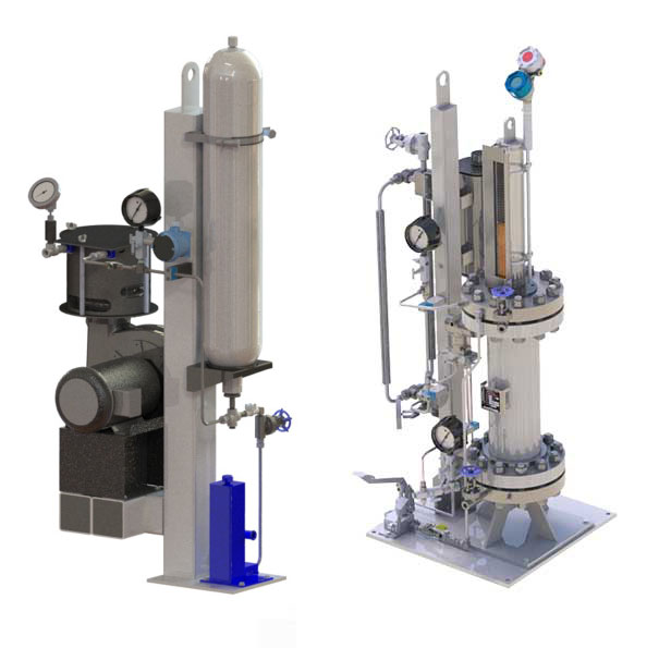
Our MP53B unit supplies an external barrier fluid pressurized by a bladder accumulator. This sends clean barrier fluid to the dual seal at a pressure greater than the seal chamber.
The external barrier fluid is pressurized by a piston accumulator and supplies clean barrier fluid to the dual seal at a pressure greater than the seal chamber.
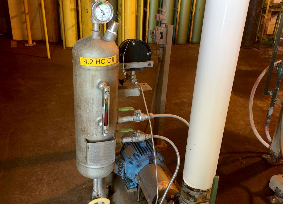
A pressurized external barrier fluid reservoir forces the circulation of clean fluid to a pressurized dual mechanical seal, lubricating the inner and outer seal faces. The reservoir can be equipped with level, pressure, and temperature instrumentation to provide real-time process feedback on mechanical seal health.
Depending on your specific needs and application, Flexaseal can help you identify the ideal products. Contact us to tell us about your needs and request a quote.
Chesterton 662 FG is an ISO VG Grade 22 high-performance lubricant designed specifically as a barrier fluid for double mechanical seal applications. 662 FG is suitable for all industrial and food/beverage/pharmaceutical applications. 662 FG is NSF H1 registered.
The ultra-clean 662 FG delivers premium thermal stability while minimizing the abrasive-particle wear of the seal faces and extending equipment life.

Flexaseal offers replacement seals for a full array of compressors, mixers, pumps, and other rotating equipment. Direct replacements are available in standard inch and metric sizes and materials for major brands, including
With four (4) configuration options all incorporating additional engineered features such as reverse pressure capability, non-clogging multi-springs, rugged seal drive operation, and hydraulically balanced faces, the RKCS single and RKCD dual seals successfully contend with the industry’s toughest slurry challenges.
Flexaseal provides component seals for a wide range of challenging applications where cartridge seals are impractical or incompatible with current rotating equipment. This may be due to equipment not having a seal chamber or the seal need to be installed on the wet side of a pump. We offer a sturdy single spring component seals, externally mounted mechanical seals for extremely corrosive applications, and stationary seats (mating rings).
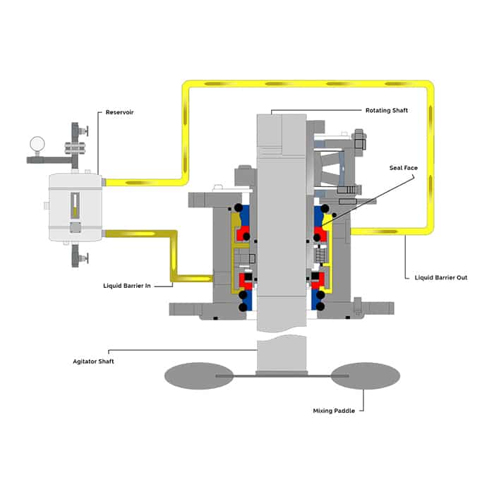
There is no one universal seal for all mixer applications. Every mixer, agitator, and reactor model is distinctive and engineered for a specific application. Many of these applications require seals to perform in environments that would destroy common seals due to extreme drag and shear forces, abrasive materials, or other challenges. That means successful sealing requires clearly defining the type of equipment, the product, and the sealing conditions. Flexaseal’s design and engineer team are capable of providing innovative solutions for your toughest challenges.
The mechanical seal style GFR/GFL offers a number of benefits over liquid lubricated dual seal for API plans 53 and 54. These include lower maintenance costs for the seal and support system since there is no barrier fluid to fill and the ability to retain 100% product purity through the use of nitrogen as a lubricant.
The resultant gas film pressure provides an opening force slightly greater than the net closing forces, which cause the faces to separate and not contact.
Simple support system – utilizes API 682 Plan 74 instead of more complex Plans 53 or 54, lowering the cost of operation and maintenance of the seal support system
Viscous substances such as syrups, tars, thick oils, resins, and glues prove to be challenging for most mechanical seals. Lip seal designs have been the go-to option for these processes that have centipoise values well above the normal range for seal face operation. The MLC3 cartridge seal achieves optimum pumping rates at lower speeds with fewer sealing issues than products currently in the field and requires virtually no seal support system.
Machined lip seals with deflected lip geometry ensures reliable sealing while producing a smaller footprint compared to competitor designs. This smaller footprint reduces parasitic torque and heat generation.
Single Lip Seal with anti-rotation ring and integrated back up ring: Energized front lip prevents leakage when transitioning between high viscosity and high fluidity processes. Anti-rotation rings statically seal even under normal temperature cycling. The integral back up ring provides added lip support under higher pressures and potential pressure spikes.
Double Lip Seal with anti-rotation ring: The PTFE-ML compound is formulated with a lower coefficient of friction, which coupled with the enhanced heat dissipation leads to lower under-lip temperatures. Lower temps = lower seal and sleeve surface wear.
Lantern Ring: Multifunctional PTFE ring provides additional bearing support as well as even dispersion of lubricant or barrier/buffer fluid around the lip seals.
Energized O-ring front lip tolerates lower speeds and higher shaft runout. This design increases sealing viability with certain emulsifiers and fluid viscosity transitioning such as CIP applications.
Sleeve: Sintered Silicon Carbide sleeve for durable wear and sealing surface. Inboard and outboard sleeve O-rings dampen vibration and aid in easy removal and repair.

This website is using a security service to protect itself from online attacks. The action you just performed triggered the security solution. There are several actions that could trigger this block including submitting a certain word or phrase, a SQL command or malformed data.
As operators of pumping equipment become more focused on the safety, reliability and environmental impact resulting from shaft seal leakage, dual mechanical seals have become more prevalent in the industry. A dual mechanical seal offers a second (outer) seal to contain the pumped fluid by creating a cavity or chamber between the inner and outer seal that can be filled with a fluid. When this fluid is unpressurized, it forms a buffer between the pumped fluid and atmosphere and is commonly referred to as a buffer fluid. When pressurized, it forms a barrier between the pumped fluid and atmosphere and is known as a barrier fluid.
Although mechanical seal designs are available in configurations that use either a liquid or a gas as a barrier fluid, the following discussion focuses on liquid buffer and barrier fluids only. In addition to separating the pumped fluid from the atmosphere, liquid buffer and barrier fluids lubricate the mechanical seal and transport frictional heat and absorbed heat from the mechanical seal to a heat exchanger. This controls the fluid’s temperature and lubricating properties.
Buffer/barrier fluid can be stored, monitored and delivered using many methods. Each is identified by a piping plan number that describes the minimum requirements of each system. The most commonly referenced piping plan originates from the American Petroleum Institute’s standard API 682.
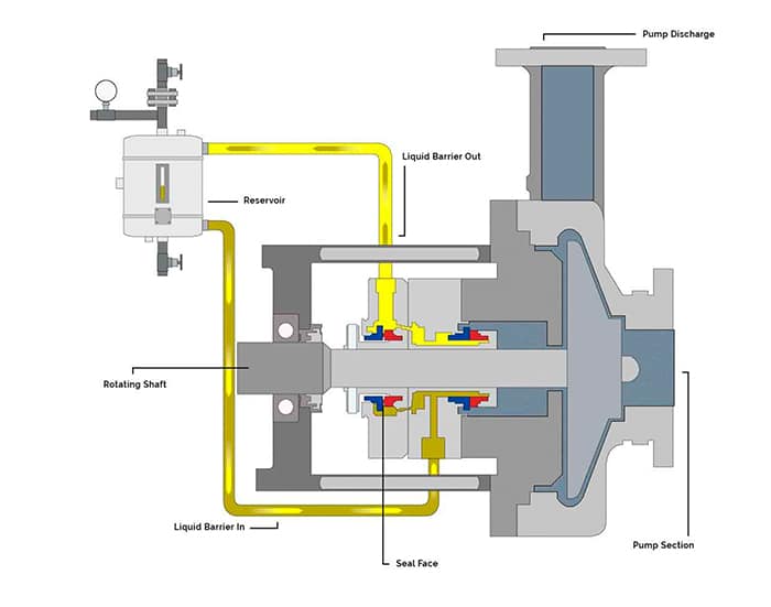
A Plan 52 system (see Figure 1) provides a reservoir that stores the buffer fluid. Supply and return lines are connected to the mechanical seal and circulation of the buffer fluid is achieved by an internal circulating device (pumping ring) within the mechanical seal. The vapor space above the buffer fluid in the reservoir is vented to atmospheric pressure typically via a flare or vapor recovery system. The reservoir can be instrumented to measure the liquid level and pressure in the reservoir. Ports are fitted to the reservoir to facilitate maintenance activities—such as inspection and cleaning or refilling and draining the buffer fluid. Cooling is accomplished using an internal heat exchanger.
Pressurized dual seal systems contain the same essential components as an unpressurized system. However, they also contain a way to pressurize the barrier fluid. The following plans may be used for pressurized dual seal systems:
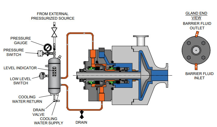
Plan 53A—A pressurized gas blanket in the reservoir pressurizes the fluid. Nitrogen is normally used and the pressure is controlled via a pressure regulator (see Figure 2). The barrier fluid is in direct contact with the pressurized gas.
Plan 53B—Pressure is generated as a nitrogen-filled bladder is compressed by the addition of barrier fluid into the bladder accumulator. The bladder prevents direct contact of the pressurized gas with the barrier fluid.
Plan 53C—A pressure amplifying piston uses pressure from within the pump (typically the seal chamber) to amplify the barrier pressure by the ratio of the area on each side of the piston. The barrier fluid is not exposed to any pressurized gas.
Plan 54—An external system is used to pressurize and circulate the barrier fluid. A Plan 54 system can be broadly classified into two groups: closed- and open-loop systems. In closed-loop systems, the barrier fluid is stored in a large reservoir and pumps pressurize and circulate the fluid. In open-loop systems, a compatible process stream is used as the barrier fluid and is circulated through the mechanical seal and returned to another point downstream in the process.
Several critical properties of a buffer or barrier fluid must be considered when making a selection. An ideal buffer or barrier fluid will have the following properties:
Water offers several benefits as a buffer/barrier fluid. Its thermal conductivity is about three times greater than oils and its specific heat is about twice that of oils, so it is good at transporting heat away from a mechanical seal. Water is inexpensive, easy to handle and store, has few seal material compatibility issues and is nonflammable. It is also compatible with many aqueous pumped solutions. Its viscosity is generally around 1 centistoke at moderate temperatures which offers low resistance to flow in the barrier system.
However, the viscosity becomes low at elevated temperatures limiting its effectiveness as a lubricant for the mechanical seal faces. Water is also susceptible to freezing during the winter months. This results in a narrow window of service and environment temperatures in which water can be used.
Generally, oils can be used in a much wider range of service temperatures. Compared to water, oils offer greater fluid stability at elevated temperatures and are not susceptible to freezing. They also provide excellent lubrication of the mechanical seal faces and, therefore, have the potential to offer longer seal life. Few compatibility issues with mechanical seal materials exist.
Oils are available in a wide range of types, compositions and viscosities. Traditional oils used in the industry include turbine oils and automatic transmission fluids. However, performance as buffer and barrier fluids has not been as successful as other oils, primarily because of the complex mixture of additives in these fluids.
Good performance can be achieved from oils with viscosity below that of ISO Grade 32 oils. High viscosities can result in damage to the mechanical seal faces, particularly when carbon is used as a face material. Paraffinic-based oils also generally perform better than naphthenic oils while synthetic oils offer even better performance. Synthetic lubricants specifically developed for use as a buffer/barrier fluid are now available in the marketplace and offer excellent performance. However, this performance is achieved at the sacrifice of cost.
We invite your suggestions for article topics as well as questions on sealing issues so we can better respond to the needs of the industry. Please direct your suggestions and questions to sealingsensequestions@fluidsealing.com.
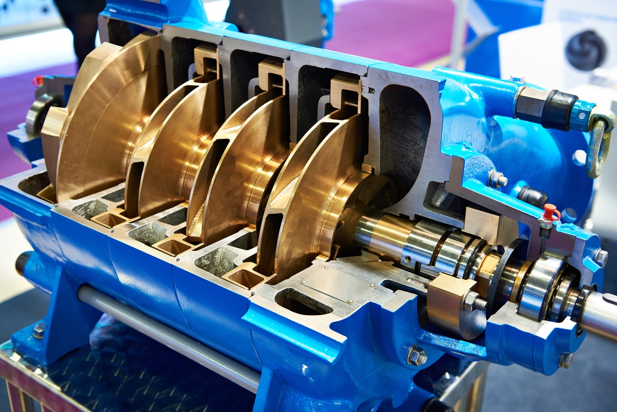
Most pump experts would agree that mechanical seals on a rotating industrial pump are one of the most important components regarding pump performance and longevity. Rotating industrial pumps are designed with double mechanical seals located at the shaft that connects the impeller or rotor to the motor. As the motor applies force to the shaft, the shaft spins, which in turn, spins the impeller or rotor which is connected to the far end of the shaft. This spinning action of the shaft and impeller or rotor is what produces the flow rate of the pump. The double mechanical seals are a wear component that must be replaced periodically or the pump will not perform as expected, or even worse if these seals fail it can cause a catastrophic failure resulting in substantial cost to repair or replace the pump.
Most often, failure of the mechanical seals is due to being exposed to excessive heat that is generated by the turning or spinning action of the shaft. This build-up of excessive heat at this area of the pump is also the reason why many rotating industrial pumps cannot operate in a run-dry condition. When a pump runs dry without fluid circulating through the wetted path, a greater amount of heat is generated at the mechanical seals. Subjecting the mechanical seals to a greater amount of heat than what they can withstand causes premature failure of the seals.
A solution to avoiding the overheating of mechanical seals in a rotating industrial pump is Seal Support Systems. Seal Support Systems are designed to flush the mechanical seal area of the pump with fluid. This flushing action reduces the build-up of heat, increases the longevity of the pump, and avoids premature failure of the mechanical seals due to overheating.
There are a number of different Seal Support System designs available on rotating industrial pumps. Some of the different designs available meet the American Petroleum Institute (API) standards for pumps that are to be used in the Oil and Gas industry. A couple of the most prevalent API standards for Seal Support Systems API Plan 53A and API Plan 62. Both of these systems are designed differently; The API Plan 53A Seal Support System is designed with a closed-loop system, and API Plan 62 Seal Support System is designed with an open system where the flushing fluid is immediately discarded from the pump directly after the flushing fluid flows through the mechanical seal area and expels the heat.
Both of these seal support systems are very effective at reducing heat build-up that can destroy mechanical seals. Although both of the types of seal support systems reduce heat build-up, some environments require the use of a closed-loop seal support system to avoid the flushing fluid from exiting the pump and contaminating the area that the pump is operating.
A singlemechanical seal consists of two very flat seal faces that are forced together by a spring and slide against one another. Between these two faces is a thin fluid film generated by the process fluid or pumped product. This fluid film (typically gap of 1 micron or 75 times narrower than a human hair), lubricates and cools the seal. An absence of this thin fluid film (pump running dry or product flashing) results in frictional heat and ultimately the destruction of the mechanical seal.
The sealed fluid typically enters the gap between the seal faces as a liquid. As it migrates across the seal faces from the high-pressure side to the atmosphere, its pressure drops, and temperature rises. The liquid may vaporize so there may be no visible liquid leakage. A correctly specified seal operating properly will typically meet VOC emissions standards.
A dual mechanical seal consists of two seals arranged in a series. The inboard seal keeps the product contained within the pump housing. The outboard seal prevents the barrier or buffer liquid from getting into the atmosphere.
Double Seal: With barrier fluid pressure higher than product pressure the seal prevents leakage of toxic or hazardous fluids into the environment. The barrier fluid provides lubrication to seal gasses and non-lubricating fluids.
Tandem Seal: By using a buffer fluid with pressure to lower than process, the seal can reduce the pressure differential across a single set of seal faces.
Spare Seal: With unpressurized buffer fluid the outboard seal operates “at idle” as a standby seal. If the inboard seal fails, the outboard seal provides primary protection, eliminating unscheduled shutdown of batch processes.

If you are human user receiving this message, we can add your IP address to a set of IPs that can access FederalRegister.gov & eCFR.gov; complete the CAPTCHA (bot test) below and click "Request Access". This should only be necessary once for each IP address you access the site from.
If you want to request a wider IP range, first request access for your current IP, and then use the "Site Feedback" button found in the lower left-hand side to make the request.
Identifying and solving mechanical seal and seal support problems doesn’t have to be guesswork especially if you’re new to the complexity of refinery processes. The diversity of centrifugal pumps, their process applications, and mechanical seal support systems can be overwhelming. Even with the dozens of mechanical seal support system configurations (API 682 Plans, as they’re known in the industry), a methodical approach to troubleshooting can help isolate and resolve the problem more efficiently.
Based on my years of working with maintenance personnel in Bay Area refineries, I’ve summarized below in tables and bullet points a quick mechanical seal support troubleshooting guide.
The first question I always ask, especially in Bay Area refineries that have been operating for decades—with infrastructure and processes designed for crudes that were predominant years ago—is: Have there been changes in process conditions that could impact the reliability of the mechanical seal and seal support system? Some of the process changes that many require corresponding changes to mechanical seals and their support systems include:
Higher temperature process fluids that exceed the rated capacity of the mechanical seal or seal support system (prolonged, excessive temperatures eventually lead to mechanical seal failure)
Increased upstream pressure is not properly compensated by the pressure of barrier fluid supplied to dual mechanical seals, resulting in process fluid migration across the inboard seal, undermining mechanical seal integrity leading to process fluid leakage
Decreased upstream pressure is not properly compensated by the pressure of buffer fluid supplied to dual mechanical seals, resulting in buffer fluid migration across the inboard seal, potentially contaminating the process fluid
Process changes don’t always result in an immediately recognizable problem. But you can avoid potential problems by making sure that any changes to pumping process parameters—fluid composition, temperature, or pressure—are checked against the rated capabilities of the pump, mechanical seal, and seal support system.
An experienced mechanical seal and your local seal support system vendor can provide the guidance to help troubleshoot problems that are the result of changing process conditions. A change of mechanical seal type or design or an upgrade of an existing mechanical seal support system is often the fast path to reliability.
Now that I’ve cautioned you on process changes that can cause trouble, let me focus on troubleshooting the problems associated with seal support system functions. In this section, I’m assuming the mechanical seal and seal support system have been correctly matched to the pumping conditions. Any single problem can have multiple effects on the support system, for example, a clogged orifice can reduce flow, pressure, and the ability to dissipate seal chamber heat.
I’ve structured this mechanical seal support troubleshooting guide, according to the most common categories—process side, dual seals, and atmospheric—for these systems.
Process side seal plans deliver process fluid (API Plans 11, 12, 14, 21, 22, and 41), a compatible flush fluid (API Plan 23), or flush fluid from an external source (API Plan 32) to the seal chamber to lubricate the seal faces and maintain the proper seal chamber temperature and pressure for single seals. In the table below I’ve listed the most likely mechanical issues to look for when troubleshooting poorly performing seal support system plans.
This plan falls under the process-side category, but rather than using process fluid to maintain the proper seal chamber environment, API Plan 32 delivers a clean flush fluid into the seal chamber from an external source. That could be water, a water/glycol mixture, or oil-based fluid that is compatible with the process fluid.
When troubleshooting API Plan 32, look for an insufficient flow of external flush fluid (supply valve, depleted reservoir) and improper throat bushing clearance that allows too much flush fluid to migrate past the bushing into the process fluid. You don’t want to be using more flush fluid than is absolutely necessary.
There are a few other plan-specific things to consider to help permanently remedy frequently-occurring problems with process-side seal support systems. For API Plans 12, 22, and 32 that use a strainer or filter, including a bypass around the strainer/filter segment of the tubing can help eliminate any downtime associated with strainer/filter cleaning or replacement. And if the strainer/filter changes seem to be too frequent, you should consider upgrading to API Plan 41 which uses a cyclone separator to remove particulates.
Dual seal support systems circulate fluid between the inboard and outboard seals, providing a pressurized (API Plans 53A, 53B, 53C, 54 using barrier fluid) or unpressurized (API Plans 52, 55, 72 using buffer fluid) to maintain seal integrity and prevent leakage of process fluid.
For each of these API plans, the buffer or barrier fluid must be chemically compatible with the process fluid. That may seem obvious, but I’ve seen situations where process fluid conditions have changed and barrier or buffer fluids were no longer able to maintain the required seal chamber environment.
API Plans 53B and 53C use a bladder accumulator and piston accumulator respectively to maintain the required barrier fluid pressure. These additional components add some troubleshooting complexity. If you’re having problems maintaining the correct barrier fluid pressure you’ll need to look at the source of charging gas (53B) or the piston operations and differential pressure indicator/transmitter (53C) that could be the source of the problem.
Both API Plans 54 and 55 are custom-engineered solutions. They include pumps and reservoirs and a wide range of optional components such as strainers, heat exchangers, and pressure and flow control valves that fine-tune performance to the needs of the pumping process.
This category is relatively simple in number and in design. These plans provide a clean quench to a single atmospheric side seal to prevent process fluid icing or coking. The clean quench can be water, steam, or plant nitrogen. In addition to issues with tubing, connections, and instrumentation, look for a depleted level of quench fluid in the reservoir for API Plan 51. And for API Plan 62 troubleshooting, ensure that plant water, steam, or nitrogen is being supplied consistently.
Troubleshooting is part of every maintenance professional’s job, but you shouldn’t get bogged down in troubleshooting recurring problems associated with outdated mechanical seal support systems. Replacing outdated or inadequate components can boost reliability and lower your maintenance costs. In some cases, the best solution is a complete replacement with a mechanical seal support system that is designed to meet specific pumping requirements.
Swagelok has decades of experience working with refineries in consulting on-site to assess the specific mechanical seal support system requirements. That hands-on consultation allows Swagelok to develop detailed CAD drawings of the proposed system for your review and approval. We’ll fabricate and thoroughly test the system in our Fremont facility following ISO 9001 guidelines. The result—fast turnaround, from consultation to delivery, of the highest quality mechanical seal support systems configured to your requirements and backed by Swagelok’s Lifetime Warranty. And being local, Swagelok is available for follow-up technical support, on-site or by phone.
Need help finding the right solutions for the mechanical seal support systems you’re troubleshooting?Swagelok Northern Californiahas helped Bay Area refineries improve the centrifugal pump reliability by providing expert consultation and Assembly Services,contact our teamtoday by calling

With barrier fluid pressure higher than product pressure, the AST80 prevents leakage of toxic or hazardous fluids into the environment. The barrier fluid provides lubrication to seal gases and non-lubricating fluids.
With unpressurized buffer fluid, the outboard seal of the AST80 runs "at idle" as a standby seal. If the inboard seal fails, the outboard seal provides primary protection, eliminating unscheduled shutdown of batch processes.


 8613371530291