
buy mechanical seal free sample
Back to back: Two rotating seal rings are arranged facing away from each other. The lubricating film is generated by the barrier fluid. This arrangement is commonly found in the chemical industry. In case of leakage, the barrier liquid penetrates the product.
Face to face:The spring loaded rotary seal faces are arranged face to face and slide from the opposite direction to one or two stationary seal parts. This is a popular choice for the food industry, particularly for products which tend to stick. In case of leakage, the barrier liquid penetrates the product. If the product is considered “hot”, the barrier liquid acts as a cooling agent for the mechanical seal.
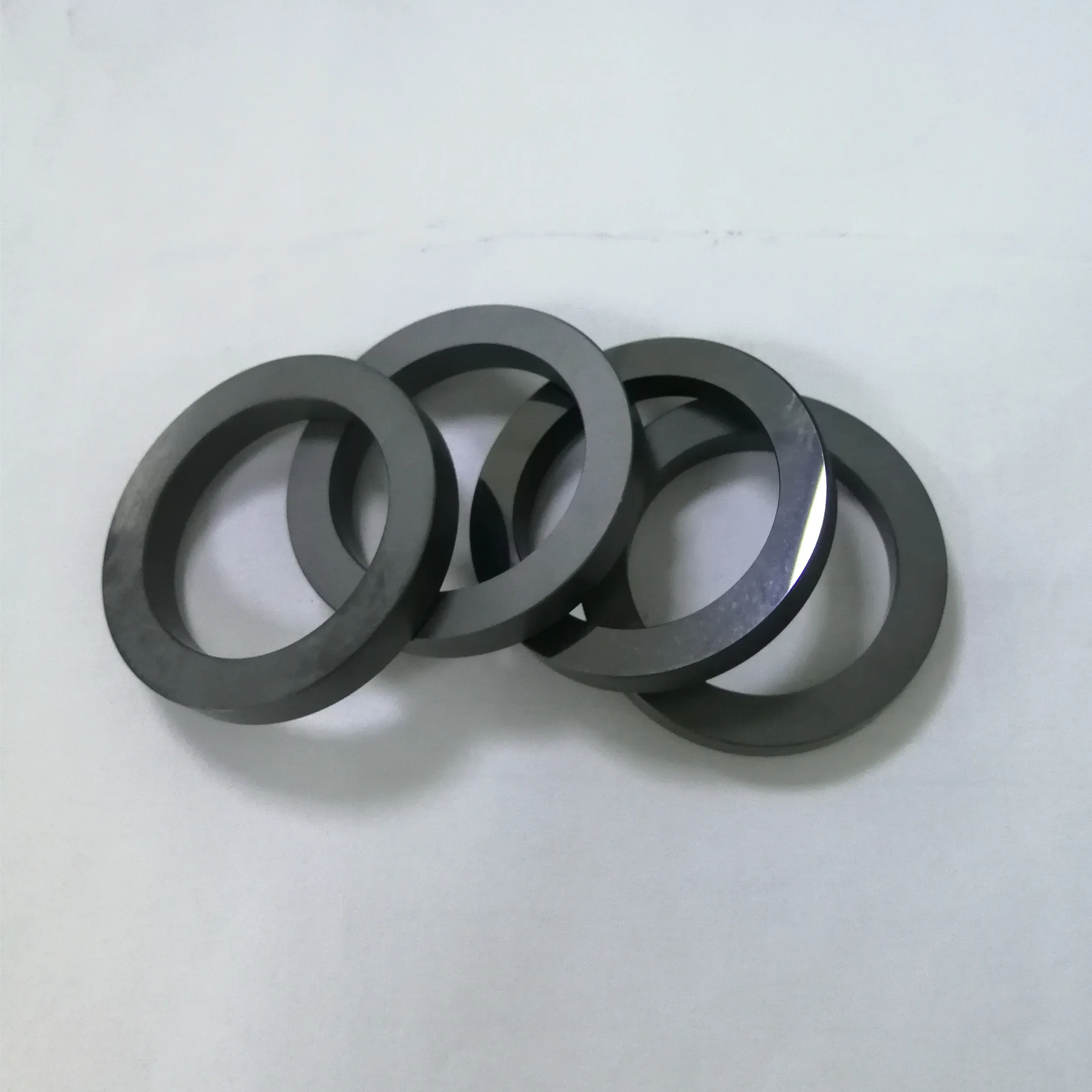
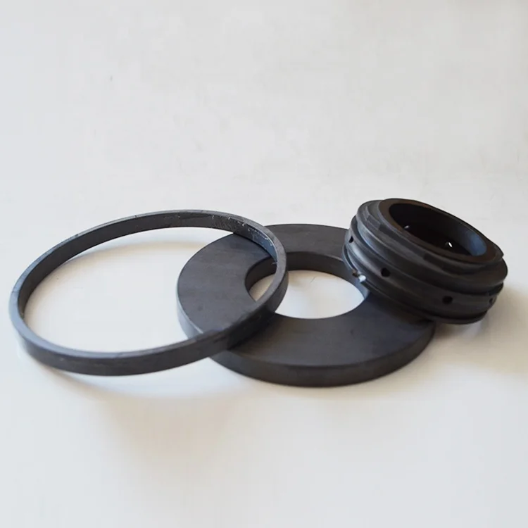
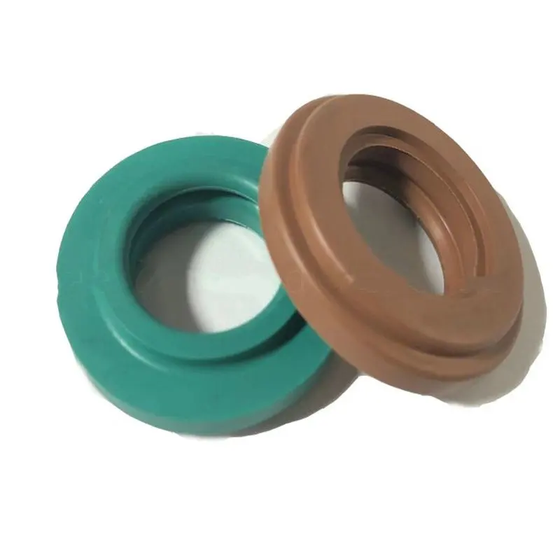
Users can choose different material for this double mechanical seal 208, matching for different liquid conditoncarbon, silicon, and tungsten carbide for this mechanical seal as seal face, if for high temerperature, we suggest to choose rubber seal viton for the rubber parts.
Lepu seal make this dual mechanical seal for many years, and offer professional suggestion when client need this grundfos seal, so we are your reliable specialist for grundfos mechanical seal.
Double mechanical seals are commonly used in the following circumstances:If the fluid and its vapors are hazardous to the operator or environment, and MUST be contained
Guangzhou Lepu machinery CO., LTD becomes one of the leading mechanical seal supplier in south of china, we focus in designing and manufacturing mechanical seal for many kinds of famous brand pumps, our mechanical seal cover many kinds of industry like food, petrol chemical, paper making, sea ship, and so on.
2. The product features low maintenance. No sealers or special polishes are needed. People can only use soap and water to maintain. Lepu seals are designed and manufactured rigorously
AES cartridge mechanical seal convertor II LP318 is designed to replace two-part component seals and conventional packing arrangements. This seal is a cartridge seal type with Short external length.
AES cartridge seal convertor made by lepu seal with a longer durable and resistance even running in bad environment, strong quality stainless steel for the cartridge seal frame, and high density silicon for the seal face, Viton rubber offer more resistance against corrosive medium.
As a leading mechanical seal manufacturer, Lepu seal factory make this AES cartridge seal for a long period, and sell this seal to hundreds of clients, 100% a right replacement for original AES seal.
Guangzhou Lepu machinery CO., LTD becomes one of the leading mechanical seal supplier in south of china, we focus in designing and manufacturing mechanical seal for many kinds of famous brand pumps, our mechanical seal cover many kinds of industry like food, petrol chemical, paper making, sea ship, and so on.
The shaft seal is a sealing element which seals the rotating shaft, of a centrifugal pump where it passes through the non-rotating pump casing reducing fluidleakage to atmosphere or the entry of air from outside to a certain level, and keeps wear of the sealing faces as low as possible.
Pumps are specially designed and manufactured to cater for a whole range of different applications. This process takes into account aspects such as resistance to the fluids handled, temperature and pump pressure. The appropriate seal type for the individual pumping requirements is chosen from a wide variety of different shaft seals.
The design is based on one of the two following principles: sealing by means of a narrow radial gap (parallel to the shaft axis) or a narrow axial gap (at a right angle to the shaft axis). For both sealing principles, the gaps may either employ a contact or non-contact design.
If only non-contacting controlled gap seals are used, a considerable amount of leaking fluid can always be assumed. This sealing system is therefore less suitable for environmentally harmful fluids handled.
Shaft seals are by their nature susceptible to leakage, and with some types leakage is actually essential to ensure proper sealing functioning. The suggestion that a seal shaft provides "zero leakage" is therefore misleading. However, depending on the seal type chosen, the amount of leakage
can vary considerably. A volute casing pump with a circumferential speed at the sealing area of 20 m/s and a pressure to be sealed of 15 bar which uses a gland packing for sealing has a leakage rate of about 5 – 8 l/h, while the leakage rate of a mechanical seal used under the same conditions is only approx. 6 cm3/h (0.006 l/h).
The leakage rate of 4 to 6000 l/h for a boiler feed pump sealed by a floating ring seal is particularly high; in this case, the diameter to be sealed is 200 mm and the pressure 40 bar, the
Due to differences in pump designs the individual seal types are not necessarily suitable for every type of application. The type of seal to be employed depends on the sliding velocity, the pressure to be sealed and the fluid temperature.
In the case of contact-type dynamic shaft seals, the parts to be sealed move relative to each other. For this reason lip-contact and line-contact shaft seals (e. g. lip seals) are only suitable for use with very low pressure differences such as those occurring when sealing against bearing oil, and are usually not adjustable.
The packings can be adjusted and are suitable for higher pressures and circumferential speeds than lip seals. Different packing variants are used depending on whether the pump is run in suction head or suction lift operation, or whether it handles clean or contaminated fluid.
As the leakage with gland packings is relatively high compared with mechanical seals, the former are mostly employed for environmentally friendly fluids only.
If the pump is used in suction lift operation, a barrier fluid line and a lantern ring fitted after the first packing ring ensure that air cannot enter via the packing. Provided the pump handles a clean fluid, this barrier fluid is supplied via the pump"s See Fig. 5 Shaft seal
Unlike gland packings, mechanical seals have a sealing gap which is positioned at a right angle to the shaft axis. These shaft seal designs are also called axial or hydrodynamic mechanical seals. Compared with gland packings, they require less space and no maintenance.
Mechanical seals are well-suited for sealing low and high pressures and circumferential speeds. The risk of inappropriate operation is therefore very low.
However, considerable disadvantages arise through wear caused by abrasive fluids (see Abrasion). As is the case with gland packings, clean barrier or flushing fluids (e. g. cleaned by means of cyclone separators) help to keep abrasive particles away from vulnerable seal faces.
Pressed together by hydraulic and mechanicalforces, two seal faces slide relative to each other during operation. The sealing gap lies between these precisely machined seal faces and is filled with a lubricating film, generally a liquid. The sealing gap width (i.e. the distance between both seal faces) is influenced by various factors, including the seal faces" surface quality (i.e. how rough or smooth they are) and the sliding velocity.
Leakage from mechanical seals is very low; the fluid leaks into the atmosphere in the form of vapour or droplets. To calculate the mechanical seal"s leakage rate, a gap width of under 1 μm is normally assumed. Thanks to this extremely narrow gap, the leakage rate for mechanical seals is considerably lower than that for shaft seals with radial gaps.
A further important differentiating feature is that seals can be unbalanced and balanced. In the case of unbalanced mechanical seals, the seal face is exposed to the complete pressure to be sealed.
If the k value becomes smaller, the seal face loads are reduced. For this reason, only balanced mechanical seals are employed in high-pressure and high-velocity applications.
A low k value results in both an improved lubricating film and a higher leakage rate. However, an excessively low k value may in extreme cases cause the complete separation of the seal faces resulting in a loss of the sealing effect.
Alongside the hydraulic closing force, spring forces provide an additional axial force acting on the sealing gap. The springs can employ an open or enclosed design and be in contact with the fluid handled or not; they may or may not transmit torque.
The friction losses generated are lower than those of gland packings. Heat is generated in the shaft seal housing due to friction; depending on the amount produced, it can be dissipated either via convection from the seal housing to the atmosphere or via forced circulation through an externally installed heat exchanger.
Frequently used designsSingle, unbalanced mechanical seal as a typical example for a centrally arranged, conical single spring: The variant shown here is for "dead end" installation, i.e. there is no additional fluid circulation in the mechanical seal area.
Unbalanced mechanical seals are used for pressures of up to max. 15 bar and sliding velocities of up to max. 15 m/s. In general, a sufficient proportion of friction heat generated in the sealing gap can be transferred to the fluid handled and dissipated from the shaft seal housing to the atmosphere via convection. If the fluid handled is cold, the friction heat is absorbed by the fluid itself. One variant is the rubber bellows seal (bellows-type mechanical seal).
Unbalanced mechanical seal with stationary spring assembly: this design is used for higher sliding velocities and ensures the springs can reliably fulfil their task (rotary spring assembly would entail a risk of broken springs due to high centrifugal forces).
Varying spring arrangements are just one example of the distinctive features represented in the wide range of mechanical seal designs tailored for various operating conditions.
In the case of "back-to-back" arrangements, a barrier fluid is fed into the space between the two mechanical seals. Its pressure should be approx. 10 %, and at least 2-3 bar, higher than the pressure of the fluid handled by the pump.
As the barrier fluid absorbs the friction heat generated by the two mechanical seals, it must be circulated, i.e. removed from the seal cavity, cooled and returned to the seals.
The barrier fluid pressure is generated by a barrier fluid system (thermosyphon vessel) or pressure booster. In the case of tandem seals, the space between the seals is flushed by unpressurised quench liquid (quench). If the leaking fluid handled by the pump has a tendency to crystallise when in contact with air, a seal arrangement comprising two rubber bellows seals should be used. It is important that the quench liquid and fluid handled are compatible.
Instead of using an outboard mechanical seal, it is also possible to install a simple sealing element such as a lip seal or packing ring. It is fitted as a back-up seal for the main seal to prevent leakage (e. g. in the case of hazardous fluids) and to safely and reliably dissipate heat.
Tandem seals are employed when a high internal pump pressure requires distribution to two mechanical seals. The barrier fluid pressure level then lies between the pressure to be sealed and the atmospheric pressure. The pressure handled by the inboard seal corresponds to the difference between the pressure to be sealed and the barrier fluid pressure; the pressure handled by the outboard seal corresponds to the difference between the barrier fluid pressure and the atmospheric pressure. The barrier fluid must circulate in order to dissipate the friction heat generated by the seals.
These mechanical seal types are used in the boiling or pressurised water reactors of nuclear power stations and are installed in main coolant pumps to seal extremely high pressures.
The pressure must be distributed via an auxiliary system, e.g. a three-stage cascading system of throttles arranged in the seals" bypass lines. A defined amount of water flows via the bypass line. Pressure is thus reduced by approx. 33 % at each throttle. The reduced pressure at each stage"s output is the operating pressure for the next stage"s input. This throttling and recirculation of the barrier fluid ensures the pressure is reduced and the friction heat removed from the sealing stages.
In the case of boiler feed pumps, seals have to cope with high sliding velocities, heat transfer from the fluid handled and the heat generated by friction.
The sealing gap temperature is generally higher than the fluid temperature in the seal housing. The latter can be kept well below 100 °C by circulating the fluid through to an external cooler by means of suitable pumping devices inside the pump. Pumping screws, holes in the shaft protecting sleeve or small pumping discs serve as pumping devices.
Detrimental dry running of the mechanical seal may occur if the pump is operated without liquid fill and in the event of a major ingress of gas, a high gas content or the evaporation of the fluid handled. Due to its low density, the gas always tends to move to smaller diameters which is the sealing gap of seals in most cases. The presence of air in this space leads to dry running and also impedes sufficient heat dissipation from the sealing gap resulting in thermal overload of the seal faces and mechanical seal failure (heat stress cracks) within a very short time.
External cooling circuits are not used if the heat losses generated by the seal can be dissipated to the atmosphere via free convection and heat radiation.
Other forms of cooling comprise a fan impeller mounted to the pump shaft to intensify convection (forced convection). In both cases the seal housing is provided with fins, at a right angle to the shaft axis (without fan impeller) see Fig. 16 Shaft Seal, and parallel to the shaft axis (with fan impeller).
In the case of uncooled mechanical seals operated at high temperatures, the temperature in the sealing gap is generally higher than the temperatures in the sealing gaps described so far. This means that the boundary between the liquid and vapour phase in the sealing gap inevitably shifts towards the sealing gap inlet, increasing the risk of insufficient lubrication.
The sealing gap width between the stationary component and the rotating component is designed to be as narrow as possible in order to minimise leakage. However, it is important to ensure that the parts do no rub against each other. Leakage on a rotating shaft is slightly lower than during standstill.
The fluid flowing through the gap allows the pressure to be reduced in relation to the atmospheric pressure. On throttling gaps and floating ring seals this is achieved in the gap due to fluid friction and due to flow losses when the fluid enters or leaves the gap.
Floating ring sealThe major advantage of floating ring seals is the fact that the components are not in contact. However, the time and costs required to provide the barrier condensate, its treatment and relevant control equipment are substantial.
The floating ring seal consists of several short throttling rings fitted in succession which can move in a radial direction and centre themselves automatically due to the pressure distribution on the ring. A cold barrier condensate injected into the seal ensures that hot water from the pump does not escape to the atmosphere (controlled system). As long as the pump is in operation or under pressure, barrier water supply must be ensured.
The floating ring seal is occasionally employed in boiler feed pumps. Its barrier condensate quantity can be controlled via the barrier condensate"s pressure and temperature difference.
Labyrinth sealThe labyrinth seal is a firm throttling bush with a circular groove profile. As radial movement is impossible with this type of seal, the diametral clearance must be wider
Centrifugal sealThis type of shaft seal generates pressure itself in order to counteract the differential pressure to be sealed; it is frequently backed up by a standstill seal. Designed as
spring-loaded mechanical seal, it is opened by centrifugal forces at very low speeds and thus protected against wear. See Fig. 20 Shaft sealThe actual centrifugal seal (fitted as an auxiliary impeller using a liquid ring at the outer diameter) operates contact- and wear-free.
Hydrostatic sealDue its design, proper functioning of the hydrostatic seal as a non-contact seal is only ensured at pressures from 20 bar. The pump drive must not be started until this pressure level is reached.
The gap with which the seal operates may be very narrow, but it is finite, and as such exhibits a considerable leakage rate (p = 160 = 160 bar, n = 1.500 = 1500 rpm; sealing diameter at 260 mm, Q = 800 = 800 l/h). It is therefore necessary to back up the hydrostatic seal with a low-pressure seal that provides sealing to atmosphere.
See Fig. 22 Shaft sealDue to the hydrostatic seals’ operating limitation at low pressures, they have been replaced with hydrodynamic mechanical seals in many nuclear power stations.
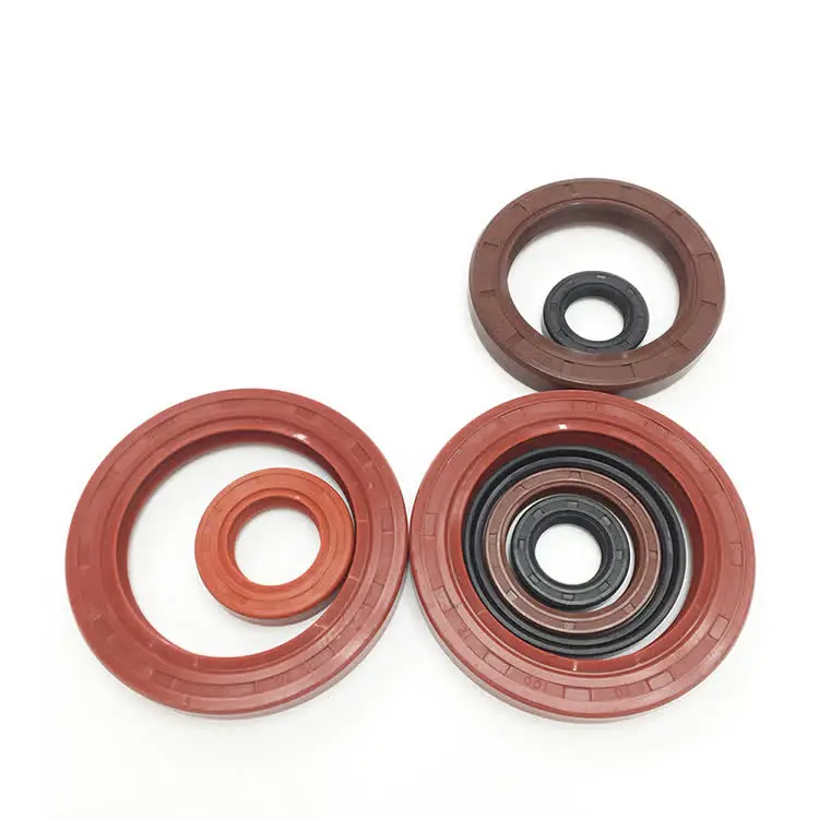
Static contact seals include O-rings. These are moulded seals and are defined as "rings with circular cross section made of elastic materials; they seal through the effect of slight bracing during installation, intensified by the operating pressure" according to DIN 3750. Their symmetrical cross-section rules out incorrect installation.
O-rings are employed on all the shaft seals described here. However, they can only be used as static sealing elements or to seal areas where slight axial movement is occasionally required.
The majority of O-rings used on mechanical seals are elastomer rings with a shore A hardness of 70 to 90. These O-rings are used for sealing between the shaft sleeves and the shaft, and between the primary ring or the mating ring and the respective components they are connected with. They ensure that the spring-loaded seal component can follow small axial shaft movements.
Their significance is often underestimated: ultimately, each shaft seal is only as good as its O-ring. O-rings must be matched to the fluid handled, cover a defined temperature range and provide good ageing resistance. Moreover, it is important to use a high-quality O-ring grease which meets the operating requirements. Besides providing long-term lubrication, the grease must be compatible with the fluid handled and must not attack the O-ring.
Elastomers which swell less than 10 % in the operating fluid and do not chemically react with the fluid handled are suitable for use as a mechanical seal"s secondary seal. A number of elastomers are available for this purpose which react differently in a reference oil with regard to temperature
Modern pumps, compressors, mixers, agitators and other rotary shaft equipment are assembled using either compression pump packing or mechanical seals to minimize emissions and fluid.
Compression pump packing controls leakage whereas mechanical seals will tend to stop any visible leakage all together, keeping work environment clean and hazard free.
Compared to compression packing the initial cost of a mechanical seal is high, however overtime, the associated cost accrued by using compression packing, for example power consumption, maintenance and downtime, could be far in excess of the initial cost of a mechanical seal, which works unattended for a long time.
Second inspection of all seal parts, which also determines whether there is abnormal wear, for example due to dry running, chemical attack or bearing damage.
You will receive a non-binding offer based on the inspections carried out. By agreement, the seal faces are ground to ensure they are parallel and all O-ring faces are polished. All elastomers and springs are also replaced. The mechanical seal is then carefully mounted and tested if possible.

A mechanical seal is simply a method of containing fluid within a vessel (typically pumps, mixers, etc.) where a rotating shaft passes through a stationary housing or occasionally, where the housing rotates around the shaft.
The report provides in-depth analysis and insights regarding the current global market scenario, latest trends and drivers into globalmechanical seals market. It offers an exclusive insight into various details such as market size, key trends, competitive landscape, growth rate and market segments.
The report also provides a detailed analysis of several leading mechanical seals market vendors that include A. W. Chesterton Company Inc., AES Engineering Ltd. (AESSEAL), EagleBurgmann Industries Ltd., Flexaseal Engineered Seals and Systems, LLC, Flowserve Corporation, Fluiten SpA, Garlock Sealing Technologies LLC, Huhnseal AB, John Crane (Smiths Group Plc), Trelleborg AB, among others.
Download Sample Report, SPECIAL OFFER (Avail an Up-to 30% discount on this report ): -https://www.quadintel.com/request-sample/mechanical-seals-market/QI043
If, in days past, you have questioned why hard piping was used for mechanical seal flush lines and seal support configurations in process pumps, you are certainly not alone.
More recently, however, American Petroleum Institute Standard 682 (API 682) began to endorse the use of tubing for some seal piping plans. Regrettably, tradition-bound purchasers still opt for hard pipe; we are asking them to reconsider.
API 682 (4thedition) now specifies seal support system connections almost interchangeably. The Fluid Sealing Association’s Technical Director, Henri Azibert, graciously gave us an update on this topic, and agreed to pass our strong preference for tubing along to the API Task Force. Mr. Azibert pointed out that the API 682 (4thedition) text now offers considerable leeway:


 8613371530291