
mud agitator design free sample
For contour impeller applications, values must be significantly faster (i.e., smaller numbers) to achieve the same results, but because of the impeller design, air entrainment is less probable. In symmetrical compartments, the fluid has a nearly equal distance to travel from the center of the impeller shaft or from the impeller blade tip before it contacts the vessel wall. Agitators should be placed where the shaft is centered in the tank or compartment.

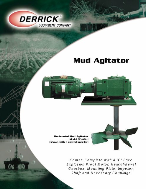
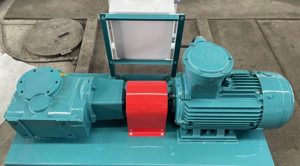
APMA series Mud agitator is combination of gear box and motor. It"s important to drilling mud process and fit on mud tanks as 3 meters per set. Except the shaker tank/compartment every tank and compartment will be fit with mud agitator. Mud agiators help to maintain mud property and keep the solids suspend for necessary mud propery and further mud process. Almost of agitator for drilling fluids system are horizontal design. On mud tanks, the separated control panel for each agitator is a good design.
Mud tank size defines agitator number and model, besides, mud property will affect agitators selection. For example, usually we put one set agitator per 3 meters on tank. According to tank width and height, the agitator can be APMA7.5, or APMA15. And if the tanks are same size, then we"ll consider the mud property. Such as mud gravity is 1.8sg we may need 7.5kw, while mud gravity is 2.4sg, we may need APMA15 driven by 20hp motor. Agitator speed defined by motor and gear box. For example, if we use APMA7.5 agitator, the motor is 10hp and speed is 1450rpm. The gear box reduce ratio is 25:1, then the agitator shaft/impller speed is 58rpm. If we use 10hp motor under 60Hz condition, its speed is 1740rpm then, and the reduction ratio is 25:1 still, then the shaft speed is about 70rpm
In a complete mud system, how many sets agitator do we need? For oil and gas drilling, there are different configuration on tanks number, tanks size, so it"s not easy to confirm. But we can take a system as an example. One mud system laying with 6 tanks, and tanks size are 9mX2.2mX2.3m. The normal proposal is 3 sets of agitator per tank. But there is a shaker tank, then we deduct 1 set. So, probably we need 17 sets of agitator. And the agitators are APM7.5 driven by 7.5kw motor.
How to select agitators? As we said just now, according to mud tank size and mud tank property. And before confirmation on agitator selection, we"d better to inquire professional engineer or consultant. There is a formula for agitator selection or design. Aipu will help user to get right solution at the best cost
Is there any other configuration on agitator type or drive system? Yes. Some clients prefer the hydraulic drive for some specific use. Some clients need the vertical agitator. And some clients prefer the stainless steel shaft and impeller. Different application and industry will request equipment much different If you have question or demand on mud mixers, please let us know and we"ll help you to get ideal solution
Moreover, APMA series agitator are flexible on gear box and motor configuration. Such as worm and worm wheel reducer, helical bevel reducer. The motor certified by IEC, ATEX, and so on

PILVAD produces side entry agitators in various sizes. They all have short and strong shafts, a powerful motor and are mounted close to the bottom of the tank.
PILVAD side entry agitators give a good mixing performance, with a well known flow pattern and ensure that all sediments are suspended to provide as efficient use of the drilling mud as possible.
PILVAD agitators are equipped with a standard mechanical seal towards internal side of the mud tank to prevent leaks. We also provide a special system for replacement of the seal, called a “shut off device”.

An improved gas trap for mud logging is vertically mounted such that its lower end (16) is constantly beneath the surface (72) of mud flowing in a tank. The mud is drawn into a housing (12) where it is agitated to release the entrained gases which are drawn off the measurement. The spent mud is returned to the tank through a mud exit port (50) and related pipe (62) to a point below the level of the mud and remote from the mud intake to the gas trap. This gas trap is insensitive to mud level changes and is relatively free of maintenance requirements.
The present invention relates to a method and apparatus for uniformly and continuously drawing samples of gas entrained in a liquid containing a high percentage of solids. More particularly, the present invention relates to a method and apparatus for obtaining samples of gases contained in drilling mud coming to the surface from an oil well drilling operation.
The conventional practice in drilling for oil is to use a special fluid, termed "drilling mud", which is pumped down the drill string to circulate from the drilling head and carry upward to the surface the debris created by the drilling operation. When a gas-containing strata is encountered by the drilling operation, a certain amount of the gas from the strata will be entrained in the drilling mud and thus be carried to the surface. Extracting these gases from the drilling mud allows determination of the presence of hydrocarbons and an estimate of the quantity of hydrocarbon being encountered. Analysis of the recovered gas can be used to make a determination as to the desirability of recovering the gas or oil from the particular strata. This practice is generally categorized as "mud logging". The known devices for accomplishing mud logging separate the gas from the fluid by an agitation or vibrating process. The gas, i.e. hydrocarbon, samples are collected in a gas trap during this operation. Gas traps of several different designs are currently used in the mud logging industry in order to extract light hydrocarbon gases from the return flow line mud for measurement. The purpose of this measurement is twofold: (1) to provide warning of dangerous underbalanced drilling conditions indicated by increased gas returns; and (2) to evaluate the formation being drilled for hydrocarbon productivity.
Several different gas traps are currently used in the mud logging industry. The purpose of these trap systems is to measure the amount of gas in the drilling fluid, which gas will be representative of the formation gas. This measurement is critical to identification of productive zones during drilling of the well. However, existing traps are not reliable and are very dependent upon operating conditions, such as mud flow rate and air dilution of the sample as it passes through the trap. These parameters cannot be readily controlled by many existing trap designs. The fluid level, where the trap is installed, will change during the drilling operation. This change in level will affect the flow of fluid through the trap thereby changing the amount of gas measured by the trap over any given time period while there is no actual change in the amount of gas in the drilling fluid.
In general, gas traps operate by diverting a portion of the return mud through an enclosed volume which provides some mechanism for gas release within that volume. The mechanism may be passive, such as a mud-spreading plate, or may contain some sort of mechanical agitator to maximize the mud/air contact. In either case, the evolved gas is conveyed to the analytical equipment by means of suction applied to a gas phase sample line attached to the trap body. Due to the need to provide continuously updated gas readings, mud residence time within the trap is normally so short that only a fraction of the gas is released. For quantitative operation, the trap design must therefore be such that the observed gas in the sample stream can be easily related to the actual gas content of the return mud.
Regardless of the details of the trap operation, several flows are always present in one form or another, mud phase entry and exit flows to permit continuous sampling of fresh mud, gas phase sampling flow, and gas phase vent flow whose direction and rate is determined by the difference in gas evolution and gas sampling rates. In order for quantitative reproducible readings to be obtained, these flows should be discreet and accessible to measurement by the operator. Of particular importance is the avoidance of uncontrolled external air and evolved gas mixing due to poor design of the trap vent flow, a failing encountered in several commonly used trap designs.
Another fault in many designs is the excessive variation in trap response with changes in the return mud level. The driller often has occasion to change the pump rate. Such flow rate changes alter the level of mud in the return mud handling equipment and, unless the trap is dynamically mounted, also alter the immersion level of the trap mud entry port. One solution sometimes is to provide an active pumping mechanism in the trap, but, due to formation cuttings in the mud, such pumps are prone to jamming and high maintenance requirements with the attendant high costs.
The present invention overcomes the difficulties of the prior art by providing a gas trap which eliminates problems with existing trap designs and provides an accurate and reliable tool for measuring mud gas. Quantitative operation is provided by inclusion of a discrete air vent line, whose far end is in gas-free air, and by elimination of uncontrolled gas phase mixing at the mud exit port and the agitator shaft feed-through. The mud exit port is sealed to gas exchange by means of a down-tube directing the exiting mud to below the external mud surface. In addition, the down-tube design is such that spent mud is directed away from the mud entry port to insure that fresh mud is continuously sampled. The invention provides immersion level insensitivity by means of an agitator design used in combination with a mud containment ring within the trap body. Finally, trap operation is made more reliable and maintenance free by means of splash protection baffles which minimize the chance for mud plugging of the vent and sampling lines.
The present invention is a gas trap which is compact, easily installed, has low maintenance requirements, provides quantitative gas recovery and is insensitive to immersion level changes encountered during normal drilling operations. The present invention is of the enclosed agitator type. In general, the present invention is of maximum simplicity and economy of design in that a number of important functions are simultaneously provided by the agitator, including, but not limited to: (1) the trap body is configured such that the agitator pumps mud through the trap by centrifugal action so that no external mud pump is required; (2) the agitator provides vigorous mud/gas phase mixing within the trap body to release the gas entrained in the mud; (3) the agitator motion causes rapid gas phase mixing of evolved gas and vent air so that the sample line gas is representative of the current gas content of the mud; (4) the agitator induced fluid flow acts to clear the trap body of mud cuttings with little operator maintenance needed; (5) the agitator design gives constant gas evolution for a given amount of gas in the mud, even with changes in the immersion level of the trap mud entry port in the mud; and (6) the agitator has means which prevent clogging due to the naturally occurring splashing of the mud within the trap.
A constant speed motor 26 is mounted coaxially on top plate 14 by means of spacers 28. A shaft 30 of the motor extends through gas tight feed-through 32 into the interior of the housing 12. A sample line 34 is connected to port 36 and a vent line 38 is connected to port 40. These ports have been shown in the top plate 14 but need not be so located. An agitator 42 is connected to the bottom of the shaft 30 and lies in the mixing chamber 24 defined between the plates 16 and 20. The embodiment of the agitator 42 shown in Figure 1 consists of a plurality of legs 44, 46, 48 fixed at their upper ends to shaft 30 and downwardly diverting so that, in revolution, they define a conical configuration. A mud exit port 50 is formed in the housing 12 above the level of the intermediate plate 20. An annular plate 52 is fixed in the housing above the mud exit port 50 to define a splash chamber 54 between plates 20 and 52. The annular plate 52 has a central aperture 56 which is coaxial with housing 12 and through which shaft 30 passes. A splash disc 58 is mounted on the shaft 30 below and immediately adjacent to annular plate 52. The splash disc 58 has a plurality of integral, radially directed gas mixing vanes 60 directed towards plate 52. A mud exhaust line 62 is connected to the mud exit port 50 and is here shown with a first downwardly bent elbow 64, a straight intermediate portion 66, a second bent elbow 68 and a short straight extension 70.
The purpose of the mud exhaust line is two fold. First, by returning the mud to below the surface of the mud 72 in tank 74, it insures that there will be no uncontrolled dilution of the evolved gas within the housing 12 from outside air. Second, it insures that the spent mud exiting the trap 10 will be returned below the level of the mud at a point remote from and directed away from the entry of the mud to the subject gas trap through aperture 18 thereby assuring that the trap 10 will be constantly working on a fresh mud supply.
The trap 10 is mounted in a conventional mud tank 74 by known means 76 such that the external mud level 72 is about midway between the lower and intermediate plates 16,20 when the rig pumps (not shown) are at their normal operating rate. This mounting of the subject trap 10 can be achieved by any of a number of known fixed and adjustable mounting means which have been schematically shown.
The length of the straight portion 66 of the mud exhaust line 62 is such that the diversion elbow 68 is located below the mud level, and preferably below the lower plate 16 as shown. The elbow 68 is spaced from and directed away from the intake aperture 18 of the trap. The trap orientation in the tank is such that the mud exit port 50 is downstream of the mud flowing past the trap. The mud enters the trap 10 via the opening 18 in the lower plate 16 at the trap bottom and is vigorously mixed by the agitator 42 in the mixing chamber 24 in order to release entrained gas. The centrifugal agitation motion causes the mud to exit the mixing chamber 24 through the opening 22 in the intermediate plate 20 and to be returned to the mud tank via mud exit port 50 and exhaust line 62. The action of the agitator 42 also causes rapid gas phase mixing of air admitted via the vent port 36 with gases released from the mud.
The purpose of the mud exit line assembly 62 and the sealed feed through 32 is to provide quantitative operation by eliminating mixing of the evolved gas with external air. Such mixing would act to dilute the evolved gas in an unpredictable fashion, particularly when the trap is subject to variable wind conditions. The diversion elbow 68 on the mud exit line assembly 62 assures that the spent mud, that is the mud having at least a portion of the entrained gas removed therefrom, is not recirculated through the trap body which, of course, would cause an erroneous reading by diluting the incoming drilling mud with processed mud from which the gas had been removed.
The air vent 40 is present for gas phase pressure equilibration and allows the suction rate of the sample line to be set at any desired level regardless of the actual gas evolution rate from the trap. The exact location of the vent port 40 in the trap body is not critical. The primary consideration for the location of the suction and vent ports is that there be good mixing of the air with the evolved gas and avoidance of plugging of the ports due to mud splashing. This latter feature is accomplished in the upper part of the trap gas sample mixing chamber 54 by fixed annular ring 52 in combination with splash disc 58 and vanes 60 mounted on the agitator shaft 30. The vent line diameter and its length are such that the end of the line away from the trap is in essentially gas free air and the line pressure drop is small at the suction flow rates of interest.
When the suction rate exceeds the total gas evolution rate, mass balance consideration show that for each gas component of interest the percentage gas by volume in the sample line is related to the evolution rate of that component by the equation %C = 100 x R/S where R = component evolution rate from mud phase in volume per unit time (such as cfh): S = suction rate measured in the same units; and %C = the percentage by volume of component in suction gas.
The operator will normally use a suction rate in excess of the largest total evolution rate whose precise measurement is of interest. When the total gas evolution rate exceeds the suction rate, the trap is saturated in that gas is lost via the vent and the above equation no longer applies. In practice a minor portion of the evolved gas may be lost via the mud exit port due to agitator created bubbles. This loss effectively increases the suction rate and may be accounted for by adding a correction term to the value for S in the equation.
The three pronged agitator detailed in Figures 1 and 3 and the intermediate plate 20 act to stabilize the gas evolution rate against changes in trap immersion level in the mud. In general the overall trap mud flow tends to increase with the immersion level. The agitator is designed to gradually lose its mud/air mixing effectiveness as it is more deeply submerged in the mud. As a result, the net evolution rate which is given by product of mud flow rate and the efficiency of mud gas removal tends to remain constant.
means (76) to mount said housing in a mud receptacle with said housing in a substantially vertical condition and with the bottom of said housing extending below the surface of said mud;
a mud exhaust line (62) connected to said exit port and extending below the mud surface and both spaced from and directed away from said bottom end (16);
A gas trap according to claim 1 characterized in that said feed-through means (32), mud exhaust line (62) and vent line means (38), in combination, prevent uncontrolled mixing of external air and evolved gas while allowing independent setting of a sample line suction flow rate.
A gas trap according to claim 1 or claim 2 characterized in that said agitator (42) comprises a plurality of members (44,46,48) fixed to said shaft (30) at their upper ends and diverging to form a conical configuration when rotated, said agitator providing a substantially constant gas evolution versus trap immersion level characteristic.
A gas trap according to any one of claims 1 to 3 characterized in that said intermediate member (20) is fixed in said housing (12) below the mud exit port (50) and together with said bottom end (16) defines a mixing chamber (24) which limits mud flow and enhances gas evolution at low trap immersion levels.
A gas trap according to any one of claims 1 to 4 characterized in that the mud exit port (50) is angled with respect to the axis of said housing to minimize mud splashing and therefore reduce resistance.
A gas trap according to any one of claims 1 to 5 characterized in that said open bottom end (16) helps control mud flow rate through the trap and immersion level sensitivity.
a second annular intermediate member (52) mounted in said housing spaced below said top end (14) and immediately above said splash disc (58) to minimize mud splashing in said chamber and improve gas mixing.

The Altern Mill is uniquely designed, offering a patented grinding chamber and disperser/mill combination for "Super-Fine" grinding. This allows for simple cleaning between formulations, saving time and money. The Mill can be fabricated in stainless steel or special steel alloys.
Jaygo is a supplier of quality Double Arm Mixers and Mixer Extruders designed to mix, blend, disperse, and knead high and very high viscosity products. Double Arm Mixers include two mixing blades, normally "Sigma" shaped, but also available in "Dispersion", or "Double Nobbin" shapes.
The Jaygo Double Ribbon Blender is a horizontal mixer/blender for a wide variety of dry, liquid or slurried products. These versatile mixers are efficient and economical. Designs are available for both the Chemical industry and also the sanitary requirements of the Food and Pharmaceutical industries. USDA and 3A DAIRY accepted designs.
The Jaygo Model DSVS Dual Shaft Variable Speed disperser is designed to disperse heavy viscous paste products. The unit has both a heavy duty mixing blade and high speed high shear dispersing blade. The heavy duty blade is designed to fit the diameter of the container. This allows the blade to pull the material from the container wall as the blade rotates.
Jaygo"s new Multi-Shaft Mixers are robust, heavy-duty mixing machines designed for the production of a multitude of products. Through the guidance of Jaygo"s sales team, customers can select equipment from a variety of agitator shapes and sizes designed to emulsify, disperse, and mix all types of products. Free flowing or wet powders can also be mixed, granulated, and dried utilizing various blade options. Typical product viscosities range from 1 cps to approximately 750,000 centipoises.
Jaygo carries a full line of pressure vessels clamps designed to work with ASME code pressure vessels. Our quick release pressure vessel clamps eliminate the need to drill holes in the flange of the vessel, eliminating the stress concentrations at the bolt holes.
When you need to gain rapid access to the essential wholesale mud agitator mixer supplies that your business relies on, head to Alibaba.com where you"ll find thousands of Chinese wholesalers ready to provide the equipment, materials, consumables and products that you need to run your business. From mud agitator mixer supplies that cover all technical specifications through to associated products and office consumables, you can buy everything that your business needs in one place at Alibaba.com.
Simply use the search filters and categories to swiftly find details of mud agitator mixer prices, specifications, order volumes, lead times, discounting arrangements and more. See what other customers thought of individual wholesalers with the customer review feature and see images of operations, markets served and more. You can even chat instantly with sales and support or send an email at any time of day.
Ready to make your mud agitator mixer order? Just do so in a few clicks in your private account area and you"ll receive regular updates on your shipment so that you know exactly where it"s at in the world until it arrives at your business! It"s swift, convenient and cost-effective to shop at Alibaba.com where you"ll find everything that your business needs to operate smoothly and without delay.


 8613371530291