
nov brandt mud agitator for sale
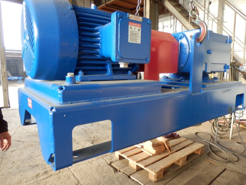
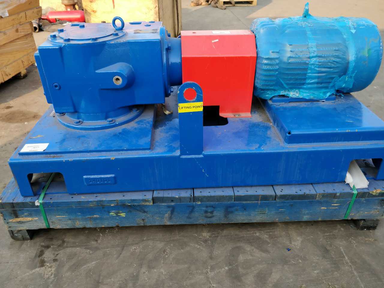
The skid mounted MA-RG agitator is compact, and its low profile reduces headroom requirements and provides more layout space on top of the tanks. The gearbox is a triple-reduction helical-bevel gear drive system that reduces the rotational speed of the motor to drive the impeller(s). Up to 95% mechanical efficiency helps reduce horsepower requirements.
Impellers are available with flat blades (radial flow), contour blades (axial flow), and canted blades (radial/axial flow). The impellers are sized according to tank volume and expected duty. Active mud system compartments—such as solids removal sections, mud mixing sections, and slug pits, which need a higher shear force to produce immediate mixing—are another consideration in impeller sizing.

BETTER produce high-efficiency mud agitator, equivalent to BRANDT™ Agitators MA series, its rugged design, simplicity and dependability have made it the preferred choice of a majority of operators and contractors.
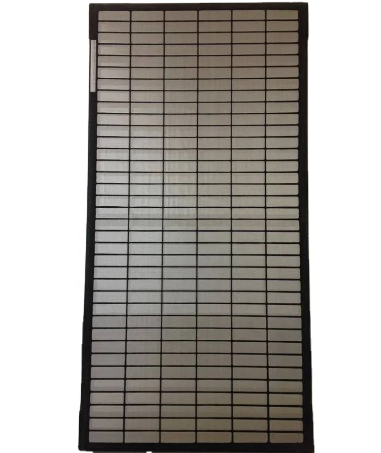
GN Solids Control is the first API Certified Company for manufacturing shale shaker screens and solids control equipment from China. GN make replacement shale shaker screens for NOV Brandt shaker and mud cleaners.
GN Shaker Screen is an important division for GN Solids Control to provide high quality & cost effective GN OEM shaker screens, and replacement NOV Brandt shaker screens.

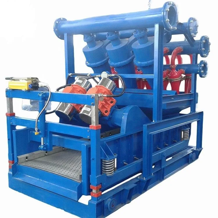
Shale Shaker is the first phrase of solid control systemin drilling fluids processing system, also known as key solids control equipment in drilling mud system, shale shaker decides performance of the whole solids control system. OilMan Solids Control can design double shakers and triplicate shakers on single skid according to clients’special requirements and also supply relevant connecting manifold, according to current industry situation.

Introducing a new range of Liquid Agitators Mixers. Australian made and fabricated from the highest quality of materials. Agitators are reliable and durable in service. Features Motors Gears Are of the highest standards and meet energy efficient standards. Available in 3 phase or single phase in all models. Nose Cone Integrated shaft support bearing lip seal. Supports the shaft loads and provides excellent sealing against oil contamination. Shaft connection is quick and reliable. Clamp Mountings Heat treated Aluminium construction for light weight, high strength and corrosion resista....
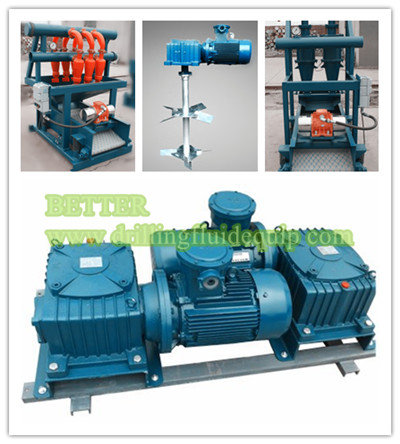
Horizontal Mud Agitator is mainly used for the stirring and mixing of drilling fluid to prevent the solid particles of the drilling fluid from depositing in the mud recycling system, so that the performance of the circulating drilling fluid is stable and the mixing is uniform.
The Horizontal Mud Agitator is mainly composed of an explosion-proof motor, a reducer, a base and an impeller assembly. The motor and the reducer, and the reducer and the impeller shaft are all connected by a rigid coupling. The impeller is assembled by welding 4 or 8 (double-layer) blades.
The impeller can make the stirring liquid produce vortex motion, thereby enhancing the stirring effect. The tray sandwiched between the blades can also prevent the solid particles of the mud from depositing around the lower blades after shutdown. This use can reduce the drag torque of the sediment on the blades during startup, thereby avoiding overloading and burning of the motor. thereby avoiding overloading and burning of the motor.

—–Liners——Mission Ceramic Liner——Mission Supreme Liner—–Piston Rods——Blak-JAK HydrA-LIGN Piston Rod System——Mission Self Aligning Piston Rod—–Pistons——Mission Green Duo Piston——Mission Slip Seal Bullitt Piston——Mission Supreme Piston——Mission Blue Lightning Piston——Mission White Lightning Bonded Piston——Mission White Lightning Slip Seal Piston—–Valves and Seats——Mission FK-1 Valve——Mission FK-N Valve——Mission Roughneck™ and Roughneck™ HP——Mission Service Master II——Mission Silver Top Valves and Seats——Mission Super Service Vavles and Seats——Service Master Drilling Valve——Supreme Valve and Seat—–Fluid End Modules and Accessories——Fluid End Accessories——-Blak-JAK Torque Pro——-Blak-JAK Torque Pro Lite——-Mission Bushing X-tractor——Liner Retention Systems——Modules (Mission L 7500 Module)—–Fluid Transfer Systems——Brine Filtration System——Centrifugal Pump Unitization Configurations——Custom Cooling Solutions——High Pressure Wash down Systems——NOV Mission Potable/Sanitary Water Pressure Sets——Resources—–Handling Tools——Adapter Rings——Air Operated Elevators——-A-Series Collar Type——-G-Series 18 Degree Center Latch——-Y-Series Slip Type——BHAT——Bushings——-Casing Bushings——-Casing Spiders——-MBH 1250——-MDSP Series——-MPCH Series——-MSPC Series——-MSP Series——-Roller Kelly Bushings——Casing Running Tools——-CRT 350 and 500 Casing Running Tool——Custom Dies and Inserts——Elevator Spiders and FMS——-BJ-250——-BJ-350——-FMS-275——-FMS-375——-V-1000——-V-500——-V-750——Hydraulic Elevators——-BX-3——BX-4-35——BX-4-50——BX-4-75——BX-5——BX-7——BXS Series——H-SJH Type——UX Horse Shoe——Links——-Perfection Links——-Weldless Links——Manual Elevators——-A-Series Collar Type——-DC Dolly——-G-Series 18 Degree Center Latch——-S-Series Auxiliary——-SBX7——-X-Series Collar Type Side Door——-Y-Series Slip Type——Manual Tongs——-HT Manual Tongs——Power Slips——-Power Slip Frame——-PS-15 Power Slip——-PS-16 Power Slip——-PS-21 Power Slip——-PS-30 Power Slip——-PF495 Power Slip——-SLT——Power Tools——-KS-6600——-KS-6800——-SSW-30——-SSW-40——-TW-61 Hydraulic Torque Wrench——Rotary Support Tables——-RST375——-RST495——-RST495 False——-RST495 Heavy——-RST495 Without Slip Ring——-RST605——-RST605 False——-RST605 Heavy——-RST605 Without Slip Ring——-RST755 Without Slip Ring——Slips——-CMS-XL——-DCS Series——-MP Series——-SD Series——-Type C——-UC-3——Resources——-BX Elevators TMS 1 of 2——-BX Elevators TMS 2 of 2——-Handling Tools TMS——-Rotary Support Table TMS—–Hoisting——Drawworks——-AHD Drawworks——–AHD-1000 Active Heave Drilling Drawworks——–AHD-1250 Active Heave Drilling Drawworks——–AHD-500 Active Heave Drilling Drawworks——–AHD-750 Active Heave Drilling Drawworks——-Drilling Drawworks——–AC Gear Driven Drawworks———ADS-10T AC Electric Gear Driven Drawworks———ADS-30Q AC Electric Gear Driven Drawworks———SSGD-1000 AC Gear Driven Drawworks———SSGD-1250 AC Gear Driven Drawworks———SSGD-360 AC Gear Driven Drawworks———SSGD-500 AC Gear Driven Drawworks———SSGD-750 AC Gear Driven Drawworks——–DC Chain Driven Drawworks———1625-UDBE DC Chain Driven Drawworks—–Iron Roughnecks——AR3200 Automated Iron Roughneck——HydraTong™ ARN-270——HydraTong™ MPT-270——Iron Roughneck Accessories——-Casing Module——-Hydraulic Mud Bucket——-Pipe Doper System——Resources——ST 100 Iron Roughneck——ST-120 Iron Roughneck——ST-160 Iron Roughneck——Jacking and Skidding——-Jacking Systems——-Jacking Claw Skidding Systems——-Rack and Pinion Skidding Systems——-Toggle Gripper System ——Lifting and Handling——-Market Segments——–Construction———SUBSEA CONSTRUCTION VESSEL———PIPELAY AND CABLELAY VESSEL———WINDMILL INSTALLATION VESSEL———CRANE VESSEL/ LIFT BOAT———IMR / WELL INTERVENTION VESSEL———ANCHOR HANDLING VESSEL——–Drilling———DRILLSHIP———JACK UP———SEMI SUBMERSIBLE———-FPSO/FPS———-SEMI SUBMERSIBLE/ SPAR/ TLP———-JACKET/ FIXED INSTALLATION——–Production———-FPSO/FPS———-SEMI SUBMERSIBLE/ SPAR/ TLP———-JACKET/ FIXED INSTALLATION——-Product Catalogue——–Anchor Handling Systems———Anchor Handling and Towing Winch———Anchor Handling Equipment Package———Secondary Winch——–Cranes———Next Generation Subsea Knuckle Boom Cranes———Box Boom Cranes———-Knuckle Boom Crane———-Single Boom Crane———-Telescopic Boom Crane———Lattice Boom Cranes———-Around the Leg Crane———-DNS Crane———-MSB Crane———-OC L Crane———-Unit Crane———Heavy Lift Cranes———-Around the Leg Crane———-MSB Crane———-Post Crane———-Tub Mounted Crane———Other Cranes———-A-Frame———-Stevedoring Cranes———Subsea Cranes———-Subsea Box Boom Crane———-Subsea MSB Crane——–Hose Loading Stations——–Mooring Systems———Mooring System for Drilling Units———Mooring System for Production Units——–Pipe Lay and Cable Lay Systems———Cable Lay Systems———Pipe Lay Systems———Tensioner———Upending Control Systems——–Riser Pull In Systems——Motion Compensation——-Crown Mounted Compensators (CMC)——-Direct Line Compensators (DLCs)——-Drill String Compensators (DSCs)——-N-Line Tensioner system——-Resources——-Tensioners——Offshore Units——-Drillship——-Fixed Platforms——-Jackup Rig——-Semi-submersible——-Well Intervention——Pipe Handling——-Horizontal Pipe Handling——–Catwalk Machines——–Catwalk Shuttle——–Pipe Deck Machines (PDM)——–Pipe – Riser Gantry Cranes——–Pipe Transfer Conveyor (PTC)——–PipeCat™ Laydown System——–Robotic Arms———DFMA-P——–DFMA-U——–UHT——-Horizontal-To-Vertical Pipe Handling——–Custom Dies and Inserts——–Hydraulic Mousehole——–Service and Access Baskets——-Pipe Handling Accessories——-Pipe Handling Cranes——-Resources——-Vertical Pipe Handling——–Racking Systems———PRS 4i/HR III———PRS5,6/HR IV———PRS8i and Hydraracker XY (HRXY)——–Standguard——Power Systems——-Hydraulic Power Units——-Motors——-Resources——-Energy Recovery——–Rotary Tables——Rotating Equipment——Structures——-Derricks——Top Drive Systems——-Fixed Electric Top Drives——-Resources——-Washpipe Systems

This document contains proprietary and confidential information whichbelongs to National-Oilwell Varco, L.P., its affiliates or subsidiaries (allcollectively referred to hereinafter as "NOV"). It is loaned for limitedpurposes only and remains the property of NOV. Reproduction, in wholeor in part, or use of this design or distribution of this information to othersis not permitted without the express written consent of NOV. Thisdocument is to be returned to NOV upon request and in any event uponcompletion of the use for which it was loaned. This document and theinformation contained and represented herein is the copyrighted propertyof NOV. National Oilwell Varco
Please take a few minutes to let us know your level of satisfaction with the NOV Brandtequipment you have recently purchased. Your comments will help identify potential areas ofimprovement. Please send this completed form to:NOVAttn.: Global Marketing2800 N. Frazier St.Conroe, TX 77303Phone: 936-523-2600Fax: 936-788-7367E-mail: brandt@nov.comSee Chapter 8, titled "Worldwide Locations" for your nearest representative.
Chapter 3: InstallationInstallation . . . . . . . . . . . . . . . . . . . . . . . . . . . . . . . . . . . . . . . . . . . . . . . . . . . . . . . . . . . . .Agitator Safety Flow Diagram. . . . . . . . . . . . . . . . . . . . . . . . . . . . . . . . . . . . . . . . . . . . .Familiarise with GA"s and Scope of Work . . . . . . . . . . . . . . . . . . . . . . . . . . . . . . . . . . .Review the Installation Manual. . . . . . . . . . . . . . . . . . . . . . . . . . . . . . . . . . . . . . . . . . . .Identify the Crates and Review the Packing List . . . . . . . . . . . . . . . . . . . . . . . . . . . . . .Handling . . . . . . . . . . . . . . . . . . . . . . . . . . . . . . . . . . . . . . . . . . . . . . . . . . . . . . . . . . . . .Planning Meeting . . . . . . . . . . . . . . . . . . . . . . . . . . . . . . . . . . . . . . . . . . . . . . . . . . .Risk Assessment . . . . . . . . . . . . . . . . . . . . . . . . . . . . . . . . . . . . . . . . . . . . . . . . . . .To Site . . . . . . . . . . . . . . . . . . . . . . . . . . . . . . . . . . . . . . . . . . . . . . . . . . . . . . . . . . .Unpack . . . . . . . . . . . . . . . . . . . . . . . . . . . . . . . . . . . . . . . . . . . . . . . . . . . . . . . . . . . . . .Component Check . . . . . . . . . . . . . . . . . . . . . . . . . . . . . . . . . . . . . . . . . . . . . . . . . . . . .Inform NOV . . . . . . . . . . . . . . . . . . . . . . . . . . . . . . . . . . . . . . . . . . . . . . . . . . . . . . . . . .Installation - Planning Meeting . . . . . . . . . . . . . . . . . . . . . . . . . . . . . . . . . . . . . . . . . . . .
General InformationThis manual contains installation, operation, maintenance and parts information. Information inthis manual should enable qualified personnel to install, operate and troubleshoot this system.Every effort has been made to ensure the accuracy of the information contained herein. NOV willnot be held liable for errors in this material, or for consequences arising from misuse of thismaterial.
WarrantyNOV warrants that, for a period of one year from the date of delivery equipment of manufacture,the Equipment shall be free of defects in materials and workmanship under normal use andservice, and provided the Equipment is used and maintained in accordance with instructionssupplied. This is the sole and exclusive warranty. If a defect in the Equipment appears within oneyear from the date of shipment, and Purchaser has given written notice of such defect within thirtydays from the discovery thereof, we will repair or replace the part, at our option, by shipping asimilar part FOB shipping point or, at our option, refund an equitable portion of the purchase price.We may require the return, to a designated location, of the defective part, transportation prepaid toestablish Purchaser"s claim.No allowance will be made for repairs undertaken without our written consent or approval.This warranty applies only to equipment manufactured by NOV Brandt. Warranties on equipmentmanufactured by others, if any, are assigned to Purchaser (without recourse) at time of delivery.Any description of Equipment, drawings, specifications, and any samples, models, bulletins, orsimilar material, used in connection with this sale are for the sole purpose of identifying theEquipment and are not to be construed as an express warranty that the Equipment will conform tosuch description. Any field advisory or installation support is advisory only. The foregoingwarranties are in lieu of all other warranties, whether oral, written, express, implied or statutory.Implied warranties or merchantability and fitness for a particular purpose will not apply. Ourwarranty obligations and purchaser"s remedies thereunder are solely and exclusively as statedherein. Purchaser"s sole and exclusive remedy, whether based upon warranty, contract or tort,including negligence, will be to proceed under this warranty.All liability shall terminate one year from the date of delivery of the Equipment.
Product InformationIntroductionBrandt MA-RG Series Agitators are heavy-duty mechanical mixers for viscous fluids. Thegearbox is a helical-bevel gear drive system that reduces the rotational speed of the motor to drivethe impeller(s). The impeller shaft is suspended from and attached to the output shaft of thegearbox.Several models are available to meet a variety of mixing needs.The naming convention for these models is:MA-XRGwhere X = the horsepower of the unit and RG indicates the helical-bevel gearbox. For example,MA-20RG is the 20 hp mud agitator with a helical-bevel gearbox.MA-RG Series Agitators are very compact. Their low profile reduces headroom requirements andprovides more layout space on top of the tanks. The 1:1 height-to-width ratio results in a lowercenter of gravity, providing stability and safety should the impeller encounter a sudden shock load.MA-RG Series Agitators use a mounting skid.An even lower profile version of the MA-RG Series Agitator is offered in which a base plate is usedinstead of the mounting skid to reduce the overall height. The naming convention for the agitatorwith a base plate is:MA-XRGLPAnother variation of the MA-RG Series Agitators has a C-face motor with a close coupling style.This variation also has a base plate instead of a mounting skid and naming convention is:MA-XRGCFor example, the MA-3RGC is the 3 hp mud agitator with a helical-bevel gearbox, a base plate anda C-face motor.Each MA-RG Agitator uses a shaft-mounted impeller to maintain a homogeneous mixture ofliquids and solids within a tank. Impellers are available with flat blades (radial flow), contour blades(axial flow), and canted blades (radial/axial flow). Blades may be installed in single or multipleconfigurations to provide the desired results.There are several options available for MA-RG Series Agitators. Popular options include specialpaint finishes, remote starters, other electrical controls, and special duty motors. Contact yoursales representative to discuss which options may be right for your application. See Chapter 8,titled "Worldwide Locations" to locate the office nearest you.
Unit DescriptionEach MA-RG Agitator consists of a motor, gearbox, mounting base and shaft-mounted impeller.Electrical controls, special coatings, custom bases, and other options are available.
MotorThe motors used on the mud agitators are explosion proof, three-phase electric motors directlycoupled to the gearbox using a flexible coupling with a solid steel guard. Motors are available formost voltage/frequency requirements. Other electrical code styles and temperature ratings arealso available.
GearboxThe gearbox is a triple-reduction helical-bevel gear drive reducing the motor speed (1800 rpm @60 Hz / 1500 rpm @ 50 Hz) to the agitator speed (60 rpm / 50 rpm respectively) in a 30:1 nominalreduction. The actual output speed varies by motor and gearbox size.The gearbox contains an output shaft, two seals, and four to six bearings in addition to the helicalbevel gear system. The bearings are generously spaced to minimize shaft vibration and deflection.Seals are standard sizes readily obtainable.
Contour-blade ImpellersOn contour blade impellers (see Figure 2-3), the blades are designed with a variable pitchreducing the horsepower requirements and inducing less shear to the mud. Contour blades moveliquid downward to the bottom of the tank, along the tank bottom toward the tank walls and then upthe tank wall. All fluid in the tank is mixed continuously and the same consistency is maintained inall parts of the tank.Field experience has confirmed that this design provides the most homogeneous mixture in thewidest range of installations. Complete fluid agitation minimizes fluid control problems caused byinconsistent mixtures. Contour blades also use less horsepower than canted blades.
Multiple ImpellersWhen an agitator is used in an extremely deep tank, over 15 feet (4.5 m) deep, multiple impellerscan be mounted on one shaft. Usually the upper impeller(s) is a canted or contour blade and thebottom impeller is a flat blade. A bottom shaft stabilizer is often required for multiple impellers.Contact our engineering department for proper impeller sizing and stabilizer requirements. SeeChapter 8, titled "Worldwide Locations" to locate the office nearest you.
Impeller ShaftStandard impeller shafts for MA-RG Series Agitators are manufactured of solid mild steel. Theimpeller shaft is coupled to the gearbox with a rigid coupling. All shafts are keyed to adjust theheight of the impeller.Shaft length is determined by tank depth. When ordering impeller shafts, always specifythe actual tank depth. Tank depth is defined as the distance from the bottom of the tank towhere the agitator is mounted.
Bottom Shaft StabilizerA bottom shaft stabilizer is required in deep tanks to reduce side loading on the gearbox bearings.The stabilizer also protects the agitator shaft and impeller when auxiliary equipment is carriedinside the mud tank during rig moves. Bottom shaft stabilizers are required when the tank depth is8 feet (2.4 m) or more.12www.nov.com/brandt
Available ModelsMA-RG Series Agitators are available in several models from 3 to 40 hp. The following table liststhe physical specifications for each agitator model.
InstallationInstallationProper installation of the agitator will help ensure proper operation with low level of vibration andlong service life. Installation should start at the top with connections then made toward the bottom.Before installing the shafts, all coupling connections must be cleaned of all debris, sand or rust. Allconnections must be torqued to the manufacturers specifications. Do not use grease or anti-seizecompound between the connections.
Agitator Safety Flow DiagramThe list below illustrates the safe and ideal steps in which to install the agitator. It is thereforerecommended that these steps are followed in order that a safe and efficient installation of theequipment will take place.
Familiarise with GA"s and Scope of WorkThe general arrangement drawings supplied are to be reviewed to assist in the location andorientation of the agitators. All personnel involved in the installation should make themselvesaware of the complete scope of the work.
Review the Installation ManualThe installers should familiarize themselves and follow the installation procedures contained in thismanual. Any issues or questions regarding installation, commissioning or use of the agitators canbe addressed by the field service representative.
Identify the Crates and Review the Packing ListWith the aid of the packing list, each agitator and shaft can be identified readily by the markings oneach crate. All crate gross weights are on the crate labels and packing lists.
HandlingPlanning MeetingFor handling the agitator and shaft crates to the site, personnel involved should attend thePlanning Meeting to decide on the safest, most direct route to move the agitator and shaft cratesinto position as close as possible to the final location.
Risk AssessmentRisk assess any potential hazard that may lead to serious injury or death when transporting theagitator and shaft crates. Hazards must then be addressed by all key personnel to ensure safetransit of the crates to the site location.
To SiteExtreme care must be taken to prevent damage when moving the agitator and shaft crates.Ideally, the use of a spreader bar with soft fabric slings is the recommended support method forlifting. Never lift a crate with only one support point. Only certified sling sets are to be used. Ideally,soft fabric slings should be used to minimise damage to the crates or components. All liftingequipment and procedures must comply with applicable safety requlations.
UnpackPersonnel should always unpack the agitator and shaft in an efficient and safe manner providing aclean and safe working environment.The equipment will be delivered to the site in crates. Remove any protective sheeting and steelbanding used to secure the crates. Remove the lid and then the sides, taking particular care not todamage the equipment or cause injury to any personnel.Any small loose items should remain in the crates awaiting storage or installation.
Component CheckAll components enclosed in the agitator and shaft crates are to be thoroughly checked against thepacking list to ensure all items have been delivered/received.
Installation - Planning MeetingPlanning meeting is to be carried out prior to installation of the agitators and shafts. A clear plan ofaction is to be deduced involving key personnel on how best to install the agitators and shaftsefficiently and safely.
Installation - Risk AssessmentAll potential hazards that may lead to serious injury or death during the installation process mustbe taken into account. Hazards must then be addressed by all key personnel to ensure a safe andefficient installation of the agitators and shafts.
Support StructureAdequate support must be made in the deck in order to support the agitator correctly. Suitablestructure should be designed based on reaction forces specified on the installation drawings (ifapplicable included in documentation package) and/or in this manual.The following information should be reviewed and taken into consideration:
Agitator weight and design loads (Refer to table titled "MA-RG Series Models" on page 11for weights of agitators and table titled "Impeller Shaft Measurements" on page 10 for shaftweights and maximum torque.)
Placement of structural members to allow full contact support for the agitator skid footprintUse of structural members of equal or higher rigidity to the material used in the agitator skidis recommended. Typically I-beams of respective strength in the lateral and horizontal bulkhead to bulk head cross sections is sufficient to support the base/skid of the agitator.
Placement of the agitatorDirectly to the tank deck is recommended. Lowering the mounting height improves thestrength of the structure and lowers the center of gravity, improving resistance to vibration.
The agitator frame should be supported by a rigid structure making the first fundamental naturalfrequency of the whole system 15 % above the operating rotating frequency of the motor andhaving following characteristics:
The agitator skid has been engineered to have the first natural frequency 50 % or moreabove the motor operating speed. The natural frequency of the combined rigid structures isdifferent than that of its components as well as dependent on the rigidity of theirconnection. Verification of the natural frequency of an as-installed structure might behelpful in eliminating any resonance. Should resonance of the combined structure occur, itcan be eliminated by modification of either the supporting structure or the rigidity of agitatorskid to support structure connection. The system natural frequency is typically directlyproportionate to its stiffness. Increasing stiffness will shift the natural frequency up, thusdecreasing the possibility of resonance. This can be achieved by:1. use of rigid, symmetrical and leveled structural support for the agitator base.2. adding cross members to the support structure.3. minimizing the gaps between the agitator base and the support structure or closing of the gaps bywelding. Minimize the use of shims.4. minimizing agitator shaft misalignment.
Below is an example of an installation where adequate primary structural support was added tostrengthen the deck area in which the agitators were installed.
Please note that sub support frames for the agitator baseplates must be suitably fabricated.Inadequately fabricated support frames can cause instability or vibration issues.
Lifting and MountingLifting should be performed with proper lifting equipment and using only the designated agitatorlifting points. The agitator should be stored and lifted with its shipping crate until it is ready to beinstalled in its final destination. The agitator should never be rested on the gearbox output shaft.Once the agitator is in its intended position, check the alignment of the mounting holes and gapsbetween the agitator skid and support structure as follows:
The gap between the agitator skid and support structure at the bolting points before boltdown should be less than 0.025 in. (0.635 mm). Gaps at the bolting points ranging from0.025 in. (0.635 mm) to 0.5 in. (12.7 mm) should be eliminated using shims to preventdeflection of the agitator skid and impact on shaft alignment.
If needed, the agitator skid can be permanently welded to the supporting structure to closeexcessive gaps between the structures. Alternatively, the support frame can be build andfitted to the agitator skid before being welded to the tank deck. Any gaps resulting fromunevenness of the tank structure can be closed while welding the support frame.Ensure that the skid is grounded before welding. Failure to do so can result inelectrical system damage.
InstallationAll MA-RG Agitators are supplied as shop assembled agitators. All shaft assemblies are brokendown into various separate parts (shaft complete with coupling/bushing assembly, impellerassembly and stabilizer housing) to aid in maneuvering parts into mud pits with restricted access.Two type of shafts are manufactured; either a solid shaft that is keyed for the impeller or a pipespool to which the impeller is bolted. The solid shaft installation instructions are given followed bythe pipe spool installation instruction on page 31.
Mechanical Installation1. Refer to the "Taper-Lock Coupling Installation Instructions" that is supplied in the"Supporting Documents". These should be reviewed to familiarise the user with the shaftfixing components being used.2. Before locating the agitator on top of the tank, ensure the surface is square and level.3. Ensure before installation of the agitator onto the top of the tank, the structure is strongenough to hold the unit and the tank dimensions are correct as per the general arrangementdrawings. It is recommended the agitators are bolted to rigid beams.4. The agitator assembly can be lifted to its location and into place using the four lifting eyesprovided on the unit and a correct four leg lifting sling assembly (not supplied). The agitatorassembly should be placed on blocks in the exact location it will be secured to give19.685 in. (500 mm) clearance from the bottom of the tank to the bottom of the shaftassembly when the shaft assembly is fitted to the agitator assembly. This is to ensure thestabilizer will be fitted in the correct location. The agitator assembly and shaft assemblyneed to be fitted before the stabilizer to ensure correct alignment.
5. Ensure access into the tanks is large enough for the shaft assemblies, impeller assembliesand stabilizers. If it is possible to assemble the shafts completely before positioning insidethe tank, skip to step 8.6. The impeller assemblies can be reduced in diameter by removing the blades, up to 4 ifnecessary.42www.nov.com/brandt
7. If the blades have been removed from the impellers, they need to be reinstalled. Refer to thesection titled "Bolt Torque Requirements" on page 102 for the correct torque for the agitatorfasteners.8. When assembling the shafts, it is advisable to use two trestles and set the shaft in betweenthem for ease of assembly. See Figure 3-8.
10. Install the impeller the correct way up. The impeller blades should be oriented so that thefluid is pushed downward when the agitator is rotating clockwise when viewed from the top,i.e. the leading edge of the paddle will be in the higher position with the trailing edge in thelower position.11. Ensure the bushing key is in the shaft keyway. Slide the impeller onto the shaft past the key.Slide on bushing over the keyway and locate with the impeller coupling.12. Locate the key and slide the impeller so that when the impeller is installed, the distance fromthe bottom of the impeller blades to the tank bottom is roughly 0.75 times the impellerdiameter. For example, if the impeller diameter is 36 in. (914.4 mm), then the distance fromthe bottom of the impeller blade to the tank bottom should be 27 in. (685.8 mm). If installingdual shafts, the top shaft impeller distance should be taken from the bottom of the top shaftcoupling connection to the bottom of the impeller blade.
26. If the shaft has been assembled outside of the tank then, using the appropriate slingingarrangement, lower the shaft through deck cut out on top of the tank. If required, the shaftcan be temporarily tied on the side of the tank.When the agitator is fitted with dual shafts, the lower shaft should be put in the tank first.
27. If the shafts are to be stored after assembly on site, preservation fluid must be applied toshafts and couplings.28. The shaft should now be assembled to the rigid coupling under the agitator gearbox as perFigure 3-17. This half coupling is fixed at the factory and under no circumstances should beremoved by the user without consulting with a field service representative.29. The stabilizer housing should never be permanently installed to the tank floor until theagitator and the shaft are installed, properly aligned and bolted down. Failure to follow thisstep may result in the shaft falling out of the rigid coupling/bushing.30. Before installing the stabilizer, make sure the tank floor is suitable to weld the stabilizer. Ifnot, weld a doubler plate on the tank floor directly underneath the shaft.31. To install, slide the stabilizer over the bottom of the agitator shaft once the impeller has beeninstalled but before the agitator is bolted down.32. The blocks should be removed and the agitator should be secured to the mud tank using themount hole pattern shown on the installation drawing, or the unit can be directly welded tothe mud tank (provided necessary risk assessments are agreed and approved).www.nov.com/brandt
See the section titled "Bolt Torque Requirements" on page 102 for the correct torque of theagitator fasteners. The shaft alignment should then be checked by rotating the impellerthrough several revolutions manually.
33. Once the agitator shaft is properly aligned, the stabilizer should be positioned so that theshaft is centered within the stabilizer.34. In the case of sloping tank bottoms, cut the stabilizer to suit the tank profile.35. Profiling the stabilizer to suit might result in losing the drain holes on the stabilizer bottom. Ifso, similar drain holes must be made on to the stabilizer before welding onto the tank. SeeFigure 3-18.
If correct position of the stabilizer location cannot be achieved:a. Check the agitator shaft runout. Make sure all connections are flush with no gapsbetween the two surfaces.b. Check for level mounting of the skid base.c.
d. It may be required to reinstall the shaft ensuring that all connecting surfaces are clean,making good contact and properly torqued.If water will be used in the tank during start up, the shaft stabilizer should be lubricated withgrease to reduce friction and minimize vibration during start up. Operation with mud doesnot require lubrication.40. Only after these steps are completed and assured that the shaft is centered within thestabilizer should the stabilizer be permanently secured to the tank floor by means of welding.41. The shaft should locate into the stabilizer at 50 % of the total height. 75 % is the maximumand 40 % is the minimum.42. Check the impeller height and adjust if necessary. Reference step 12 for the correct height.
Pipe Spool Installation1. Before locating the agitator on top of the tank, ensure the mounting surface is square andlevel.2. Ensure the support structure is adequately designed to hold the unit and the tankdimensions are correct as per the general arrangement drawings. It is recommended for theagitators to be bolted or welded to rigid beams.3. Ensure access into the tanks is large enough for the shaft assemblies, impeller assembliesand stabilizers.4. Place the skid on the foundation and ensure level of the unit. Level check should beperformed on skid main beams as well as on the gearbox housing in both directions. Propershimming is required. See the section titled "Lifting and Mounting" on page 17.5. After shimming, bolt or weld the unit to the foundation.Ensure that skid is grounded before welding. Failure to do so can result in electricalsystem damage.6. Clean all debris, grease and other contaminants from the coupling faces.7. Bolt the first pipe spool to the gearbox coupling. Torque the bolts to 40 % of therecommended torque. Torque the bolts in a series of diagonally opposite pairs. Tighten eacha little at a time up to 40 % of the recommended torque.8. Check the runout along the pipe spool to observe the trend. See Figure 3-22. Rotate theshaft by hand. Mark the high and low runout points on the bottom of the pipe by the couplingweld. Note runout values. See Figure 3-23.9. Check the runout on the bottom face. See Figure 3-23. Mark the high and low values.10. Unbolt the first pipe spool. Rotate the shaft 180 and repeat steps step 7 - 9. See Figure 324.11. Compare the two runouts and select the lower value for the next installation step.
13. Check once more the runout on the coupling face. Starting with the smaller runout side,torque the bolts in a series of diagonally opposite pairs to 100 % of the recommendedtorque. Refer to the section titled "Bolt Torque Requirements" on page 102 for the correcttorque values for the agitator fasteners.14. Prepare the impeller hub and the second pipe spool section. Clean all faces.15. Position the impeller hub the correct way. See Figure 3-25. The impeller hub blades shouldbe oriented so that the fluid is pushed downward when the agitator is rotating clockwisewhen viewed from the top; i.e. the leading edge of the blade will be in the higher positionwith the trailing edge in the lower position.16. Bolt the second pipe spool to the first pipe spool with impeller hub between the two couplingfaces. Torque the bolts to 40 % of recommended value. Torque the bolts in a series ofdiagonally opposite pairs. Tighten each a little at a time.17. Check the runout along the second pipe spool to observe the trend. Mark the high and lowrunout points on the bottom of the pipe by the coupling weld.18. If the runout is adding to the runout of the first pipe spool, rotation of the second pipe isnecessary. Using the markings on the first pipe spool, unbolt the second pipe spool, rotate it180 and re-bolt it once more to 40 % of the recommended torque.19. Check the runout once more.
20. Torque the bolts to the recommended value. Refer to the section titled "Bolt TorqueRequirements" on page 102 for the correct torque values for the agitator fasteners. Torquethe bolts in a series of diagonally opposite pairs. Tighten each a little at a time.21. For agitators with multiple impellers, repeat step 14 - 20.22. Prepare the bottom shaft stabilizer and stub shaft or pipe stub shaft (for pipe spools longerthan 35 ft [10.7 m]) for installation by cleaning all faces. Place the stabilizer and stub shafttogether underneath the hanging pipe spool. See Figure 3-26.23. Bolt the stub shaft to the pipe spool. Torque the bolts to the recommended value. Refer tothe section titled "Bolt Torque Requirements" on page 102 for the correct torque for theagitator fasteners. Torque the bolts in a series of diagonally opposite pairs. Tighten each alittle at a time.24. Before installing the stabilizer, the following checks should be performed:a. Ensure the tank floor is suitable to which to weld the stabilizer.b. Ensure the gearbox and skid are level.25. For pipe spool installation on drill ships or other semi-submersibles, weld the stabilizer inplace at the quayside.26. In the case of sloping tank bottoms, prepare a support structure for the stabilizer.27. Place the bottom shaft stabilizer in its intended position.28. Measure the shaft runout at the stabilizer by slowly rotating the shaft.
If correct positioning of the stabilizer cannot be achieved:a. Check the agitator shaft runout. Make sure all connections are flush with no gapsbetween the two surfaces and there are no shims between the pipe spools.b. Check for level mounting of the skid base.c.
30. Only after these steps are completed and it is assured that the shaft is centered within thestabilizer should the stabilizer be permanently welding to the tank floor.Ensure the skid is grounded before welding. Failure to do so can result in electricalsystem damage.31. Install the impeller blades. The impeller blades should be oriented so that the fluid is pusheddownward when the agitator is rotating clockwise when viewed from the top, i.e. the leadingedge of the blade will be in the higher position with the trailing edge in the lower position.See Figure 3-28.
32. If water will be used in the tank during commissioning, the stabilizer should be lubricatedwith grease to reduce friction and minimize vibration during start up. See Figure 3-29.Operation with mud does not require lubrication.
Gearbox and Motor Shaft AlignmentThe agitators are aligned at the factory before performance of the Factory Acceptance Test. Thealignment between the shafts should be inspected after installation of the agitator to ensure thattransportation, handling or installation has not caused a misalignment. Poor alignment can resultin increased vibration and failure or decreased service life of the coupling, gearbox or motorbearings.Alignment should not be attempted until the base is in position and the mounting and flange boltshave been tightened.
START / STOP StationThis unit is supplied by others and is out of the scope of supply.The unit should be certified for the Zone 1 and should have as high an ingress protection rating aspossible (minimum of IP56).The remote START/STOP station should be sited within an area such that the operator can ensurethat no exposed persons are in the danger zone around the agitator before operating.
Emergency Stop StationThis unit is supplied by others and is out of the scope of supply.The unit should be certified Zone 1 and have an ingress rating of IP56 minimum.The unit must be positioned for easy access and for non-hazardous operation by the operator orothers who may need to use it. Measures against inadvertent operation should not impairaccessibility.The unit should be mounted not less than 2 feet (0.6 m) above the servicing level. Ideal height is5.5 feet (1.7 m). The ideal position is such that you can see the whole agitator but do not need togo into the danger area to operate it. Other accessible locations can be considered, i.e. close todoorways, exits, etc.The emergency stop should not be used as a functional stop for the unit but should be tested on aregular basis to ensure reliable switching. Weekly testing is recommended.Use properly certified seal glands.
GeneralElectrical Cabling / DistributionEnsure each electric motor has a same voltage and frequency with the accepted tolerance limits voltage +/- 5 %, frequency +/- 2 % of the rig supply voltage.Cables will be run in accordance with the single line block diagram.Great care must be taken when wiring to the electric motors. Only use recommended cable (as perthe drawings) or its equivalent.Cables to the electric motors must be externally supported.Cable trays should be installed in conjunction with the appropriate vessel installation / assemblydrawings.Ensure the cable is free to move (without excessive movement) prior to the terminal box cableentry. Ensure the cable has sufficient length so as not to be strained during operation preferably bymeans of a loop or "pig-tail".Do not leave the electrical wires inside the terminal box too long. Always use ring type crimpswhen attaching the electrical wires to the motor terminals.Use properly certified seal glands.Unused cable entries must be plugged with appropriate certified plugs.42www.nov.com/brandt
After obtaining the correct permit for connecting electrical power, check rotation for the correctdirection. Incorrect rotation can result in serious damage to the agitator and related gearbox. Ifnecessary, reconnect the electrical leads to reverse the rotation of the agitator motor.
Long Term StorageStore the MA-RG Agitator in a cool, dry place.The MA-RG Agitator is packaged to prevent corrosion for a period of 12 months if stored indoors.During shipping, all openings are covered or capped to protect the inside from dust, rust andmoisture. Threaded connections, couplings and shafts are coated with a corrosion inhibitor.If the equipment is to be subjected to prolonged shutdown or storage, take the following steps toensure that the unit does not degrade during storage:
If water is used in the tank, the shaft stabilizer should be lubricated with grease to reducefriction and minimize vibration during start up. Operation with mud does not requirelubrication.
Oil should be within 1/2 in. (12 mm) of the bottom of the oil level hole as shown in Figure 4-1. Donot overfill.Always check the oil level with the MA-RG Agitator off.
Changing the Gearbox OilVerify the location of the oil drain plug, the breather plug and the oil level plug for your MA-RGSeries Agitator model in Figure 6-1.1. Turn the unit off.2. LOCKOUT/TAGOUT the power supply to the agitator.Allow the gearbox to cool or open the vent plug before opening the level plug. Hotoil may escape rapidly and cause burns.3. Remove the oil drain plug.4. Drain the used oil into a suitable container and replace the oil drain plug.5. Remove the fill/level plug.6. Fill the gearbox with the correct amount of acceptable oil. The gear reducer is properly filledwhen oil just begins to flow out of the oil level hole.7. Replace the fill/level plug.Gear oil is extremely slippery and sticky. Gear reducers are most easily filled using a pumpor pressurized lubrication gun. Be sure to dispose of used oil properly and clean area ofany spilled oil after completing this procedure.
Routine Maintenance ChecklistThe MA-RG Series Agitator is designed for years of dependable service with routine inspectionand maintenance. Additional copies of this checklist should be placed close to the unit for quickreference.
Startup1. Check the oil level with the agitator turned off. The oil should be within 1/2 in. (12 mm) of thebottom of the oil level hole.Do not overfill.
2. The impeller should rotate clockwise when viewed from top.3. The oil fill/breather plug must be clear of any obstruction to prevent pressure build-up andpossible seal damage.4. The agitator should operate with no vibration.5. Check the rubber insert on the input shaft coupling for wear and cracks.6. For optimal performance, change the oil after the first five days of operation, particularly ifthe unit has been in storage.
Daily1. Check for oil leaks.2. Keep the motor clean and ventilation openings clear of mud build-up or other debris.3. Check the impeller shaft coupling for proper make-up.
Parts and DrawingsRecommended Spare PartsThe following table lists the spare parts recommended for the MA-RG Series Agitator operating forone year under typical conditions. Contact your nearest representative for spare parts for otherconditions. Oil is sold in 5 gallon (18.9-liter) units only.
DESCRIPTIONCOUPLING RIGID FEMALEBUSHING SHAFTSHAFTBUSHING IMPELLERSTABILIZERIMPELLERIMPELLER 20 DIA CANTEDIMPELLER 24 DIA CANTEDIMPELLER 28 DIA CANTEDIMPELLER 30 DIA CANTEDIMPELLER 32 DIA CANTEDIMPELLER 20 DIA FLATIMPELLER 24 DIA FLATIMPELLER 28 DIA FLATIMPELLER 20 DIA CONTOURIMPELLER 24 DIA CONTOURIMPELLER 28 DIA CONTOURIMPELLER 32 DIA CONTOURIMPELLER 34 DIA CONTOURIMPELLER 42 DIA CONTOURAGITATOR S & I CHECKLISTKEY3/8" x 3/8" x 1 3/4"KEY3/8" x 3/8" x 1 1/4"
DESCRIPTIONCOUPLING RIGID FEMALEBUSHING SHAFTSHAFTBUSHING IMPELLERSTABILIZERIMPELLERIMPELLER 20 DIA CANTEDIMPELLER 24 DIA CANTEDIMPELLER 28 DIA CANTEDIMPELLER 30 DIA CANTEDIMPELLER 32 DIA CANTEDIMPELLER 34 DIA CANTEDIMPELLER 36 DIA CANTEDIMPELLER 20 DIA FLATIMPELLER 24 DIA FLATIMPELLER 28 DIA FLATIMPELLER 30 DIA FLATIMPELLER 32 DIA FLATIMPELLER 36 DIA FLATIMPELLER 28 DIA CONTOURIMPELLER 32 DIA CONTOURIMPELLER 34 DIA CONTOURIMPELLER 36 DIA CONTOURIMPELLER 38 DIA CONTOURIMPELLER 42 DIA CONTOURAGITATOR S & I CHECKLIST
DESCRIPTIONCOUPLING RIGID FEMALEBUSHING SHAFTSHAFTBUSHING IMPELLERSTABILIZERIMPELLERIMPELLER 20 DIA CANTEDIMPELLER 24 DIA CANTEDIMPELLER 28 DIA CANTEDIMPELLER 30 DIA CANTEDIMPELLER 30 DIA CANTEDIMPELLER 32 DIA CANTEDIMPELLER 36 DIA CANTEDIMPELLER 38 DIA CANTEDIMPELLER 20 DIA FLATIMPELLER 24 DIA FLATIMPELLER 28 DIA FLATIMPELLER 30 DIA FLATIMPELLER 30 DIA FLATIMPELLER 32 DIA FLATIMPELLER 36 DIA FLATIMPELLER 34 DIA CONTOURIMPELLER 36 DIA CONTOURIMPELLER 38 DIA CONTOURIMPELLER 42 DIA CONTOURAGITATOR S & I CHECKLISTKEY5/8" x 5/8" x 3"
DESCRIPTIONCOUPLING RIGID FEMALEBUSHING SHAFTSHAFTBUSHING IMPELLERSTABILIZERIMPELLERIMPELLER 24 DIA CANTEDIMPELLER 28 DIA CANTEDIMPELLER 30 DIA CANTEDIMPELLER 32 DIA CANTEDIMPELLER 36 DIA CANTEDIMPELLER 38 DIA CANTEDIMPELLER 40 DIA CANTEDIMPELLER 44 DIA CANTEDIMPELLER 24 DIA FLATIMPELLER 28 DIA FLATIMPELLER 30 DIA FLATIMPELLER 32 DIA FLATIMPELLER 36 DIA FLATIMPELLER 38 DIA FLATIMPELLER 40 DIA FLATIMPELLER 44 DIA FLATIMPELLER 28 DIA CONTOURIMPELLER 32 DIA CONTOURIMPELLER 34 DIA CONTOURIMPELLER 36 DIA CONTOURIMPELLER 38 DIA CONTOURIMPELLER 42 DIA CONTOURIMPELLER 45 DIA CONTOURIMPELLER 45 DIA CONTOURIMPELLER 52 DIA CONTOURAGITATOR S & I CHECKLIST
DESCRIPTIONCOUPLING RIGID FEMALEBUSHING SHAFTSHAFTBUSHING IMPELLERSTABILIZERIMPELLERIMPELLER 30 DIA CANTEDIMPELLER 32 DIA CANTEDIMPELLER 36 DIA CANTEDIMPELLER 38 DIA CANTEDIMPELLER 40 DIA CANTEDIMPELLER 42 DIA CANTEDIMPELLER 44 DIA CANTEDIMPELLER 48 DIA CANTEDIMPELLER 30 DIA FLATIMPELLER 32 DIA FLATIMPELLER 36 DIA FLATIMPELLER 38 DIA FLATIMPELLER 40 DIA FLATIMPELLER 44 DIA FLATIMPELLER 28 DIA CONTOURIMPELLER 34 DIA CONTOURIMPELLER 38 DIA CONTOURIMPELLER 42 DIA CONTOURIMPELLER 45 DIA CONTOURIMPELLER 45 DIA CONTOURIMPELLER 48 DIA CONTOURIMPELLER 52 DIA CONTOURIMPELLER 54 DIA CONTOURAGITATOR S & I CHECKLIST
DESCRIPTIONCOUPLING RIGID FEMALEBUSHING SHAFTSHAFTBUSHING IMPELLERSTABILIZERIMPELLERIMPELLER 28 DIA CANTEDIMPELLER 32 DIA CANTEDIMPELLER 36 DIA CANTEDIMPELLER 36 DIA CANTEDIMPELLER 40 DIA CANTEDIMPELLER 40 DIA CANTEDIMPELLER 42 DIA CANTEDIMPELLER 44 DIA CANTEDIMPELLER 46 DIA CANTEDIMPELLER 48 DIA CANTEDIMPELLER 28 DIA FLATIMPELLER 32 DIA FLATIMPELLER 36 DIA FLATIMPELLER 40 DIA FLATIMPELLER 44 DIA FLATIMPELLER 48 DIA FLATIMPELLER 45 DIA CONTOURIMPELLER 48 DIA CONTOURIMPELLER 52 DIA CONTOURIMPELLER 54 DIA CONTOURIMPELLER 56 DIA CONTOURIMPELLER 60 DIA CONTOURIMPELLER 42 DIA CONTOURAGITATOR S & I CHECKLISTKEY3/4" x 3/4" x 3 1/2"
DESCRIPTIONCOUPLING RIGID FEMALEBUSHING SHAFTSHAFTBUSHING IMPELLERSTABILIZERIMPELLERIMPELLER 36 DIA CANTEDIMPELLER 40 DIA CANTEDIMPELLER 42 DIA CANTEDIMPELLER 44 DIA CANTEDIMPELLER 48 DIA CANTEDIMP 48 DIA CANTED WITHBOLT ON PADDLESIMPELLER 52 DIA CANTEDIMPELLER 40 DIA FLATIMPELLER 44 DIA FLATIMPELLER 48 DIA FLATIMPELLER 50 DIA FLATIMPELLER 52 DIA FLATIMPELLER 48 DIA CONTOURIMPELLER 52 DIA CONTOURIMPELLER 54 DIA CONTOURIMPELLER 56 DIA CONTOURIMPELLER 60 DIA CONTOURIMPELLER 64 DIA CONTOURAGITATOR S & I CHECKLISTKEY7/8" x 7/8" x 4 1/2"
Global Headquarters for Brandt ProductSales, NOV FluidControl andNOV Portable Power4310 N. Sam Houston Pkwy EastHouston, Texas 77032United StatesPhone: 713 482 0500Fax: 713 482 0690
Global Manufacturing for Brandt ProductSales, NOV FluidControl andNOV Portable Power2800 N. Frazier StreetConroe, Texas 77303United StatesPhone: 936 523 2600Fax: 936 788 7367
The VMAI series mud agitators are a vertically mounted motor with ahelical inline gearbox. They are heavy duty mechanical mixers used forviscous fluids such as drilling fluids. The gearbox utilizes a parallel helicalgear drive system that reduces the rotational speed of the motor to drivemounted impeller to maintain a homogeneous mixture of liquids and solidswithin a tank. Impeller are available with flat blades (radial flow), contourblades (axial flow), and canted blades (radial/axial flow). Blades may beinstalled in single or multiple configurations to provide desired results.Multiple sizes and locations of impeller configurations are available. Theseagitators are sized to meet all drilling rigs needs and have a large andsuccessful install base worldwide.
The MA-RG series mud agitators are horizontally mounted motor with ahelical-bevel gearbox. They are heavy duty mechanical mixers used forviscous fluids such as drilling fluids. The gearbox utilizes a helical-bevelgear drive system that reduces the rotational speed of the motor to drivethe impeller(s). MA-RG series agitators are very compact. Their low profilereduces headroom requirements and provides more layout space on top ofthe tanks. The 1:1 height to width ratio results in a lower center of gravity,providing stability and safety should the impeller encounter a sudden shockload. MA-RG agitators use a mounting skid for robust installation. Theybeing the size and mounting configuration. Multiple sizes and locations ofimpeller configurations are available. MA-RG agitators are sized to meet alldrilling rigs needs and have a large and successful install base worldwide.
motor with a helical-bevel gearbox. These agitators are considered highpurpose design for trouble free mixing. The 20BRGT Series are backed byto allow for optimal mixing with lower HP requirements. These agitatorsdesign and testing at our mixer facility to allow NOV to create more mixingwithout consuming a lot of power due to low shear and velocities. Theseand are being installed globally today along with BRANDT solids controlequipment.
Operating as part of National Oilwell Varco (NOV), NOV Brandt Product Sales is a global provider of mechanical solids control equipment, used to remove detrimental solids from the mud system when drilling for oil.
These products are provided as part of the complete package that NOV can offer to its customers, and they are used in one of the most important phases in the drilling process.
Amongst the products offered by NOV Brandt Product Sales is the gumbo removal equipment range. The gumbo chain is positioned before the mud gas separator at the flow line, and it consists of a simple device that uses a flat, chain-type conveyor for removing large, sticky clays (gumbo) and other troublesome solids from the mud system. The chain opening size on these units can vary depending on the formation drilled and the needs of the drilling operation.
Mud gas separators also comprise an important part of the NOV Brandt Product Sales portfolio. These products are used to mechanically remove entrained gasses such as hydrogen sulphide, carbon dioxide and natural gas from the mud system, as these can reduce the hydrostatic head of the mud column and can cause catastrophic well control problems. Because such separators are one of the first units of solid control equipment arranged to treat mud, these mud gas separators are able to process all of the mud from the flowline before the mud reaches the primary shale shakers.
Shale shakers are also provided by NOV Brandt Product Sales and these are used to separate solids from liquids by using a vibrating basket outfitted with specially designed screens. Perhaps considered the most important tool for removing drilled solids, these units are responsible for removing the majority of drilled solids that are generated during the typical drilling process.
Included within this range is NOV Brandt King Cobra, which utilises four pretension screens and linear motion to remove any detrimental drilled solids from the mud system. Operating in this way means that the NOV Brandt King Cobra can minimise mud losses whilst still enhancing cutting dryness. Furthermore, maintenance on the NOV Brandt King Cobra is minimal and only a small inventory of replacement parts is necessary to sustain optimal operation. The shaker’s rugged design also offers years of reliable operation.
The NOV Brandt King Cobra Venom benefits from reduced dimensions and a lower weight, and so is able to be installed on a wider range of rigs on the market. With a new modular design and standardised platform, customers are given the opportunity to upgrade the product to meet their specific needs, regardless of how the shaker was originally configured at the factory. This field-upgradeability provides the user with a great deal of flexibility in situations of constantly changing needs.
NOV Brandt Product Sales is also renowned for its mud conditioners, which were originally designed to remove fine drilled solids from weighted mud without the excessive loss of barite and fluid. This use evolved and now their primary purpose is to de-sand weighted mud and to reclaim the liquid from the hydrocyclone during the unweighted hole section.
NOV Brandt Product Sales manufactures both negative pressure (vacuum) and atmospheric degassers. Vacuum degassers are designed to utilise negative pressure to withdraw entrained gases from the mud. Here, the mud is pumped through a venturi, where it develops a negative pressure, and sucks the mud into the main unit. This mud then flows over horizontally or vertically arranged dispersion plates, creating thin sheets of gas-cut mud. These plates can then bring the entrained gases closer to the surface for easy removal.
The atmospheric degassers are considerably less complex in their design and operation. These units simply remove the gas through mechanical means, pumping mud into a thin layer in order to allow the gas to liberate itself.
NOV Brandt Product Sales also offers horizontally mounted agitators as part of its product portfolio, and these have been used as the industry standard for many years. Due to its rugged design, simplicity and dependability, these products have gradually become the preferred choice for the vast majority of operators and contractors.
The low profile of these agitators reduces headroom requirements, and their quiet, vibration-free operation makes them a popular choice. Available from three to 30 horsepower, the NOV Brandt MA series uses a sliding action worm and gear, whereas the NOV Brandt MA-RG series is a double-reduction helical gear designed primarily for applications that require more than 15 horsepower.
NOV Brandt Product Sales offers vertical agitators through its VMA series as well, and these are ideal for installations with limited footprint availability. These double-reduction, in-line, helical gear agitators allow for smooth, vibration-free operation and efficient mixing. They also align the motor shaft with the gear reducer output shaft. Furthermore, the explosion-proof, C-face motor bolts onto the double reduction gearbox for improved efficiency.
In addition to all the other products of NOV Brandt Product Sales are the HS-3400 and HS-2172 centrifuges, which are used to process weighted and unweighted water-based or oil-based drilling fluids. By using mechanical energy to increase the gravitational force exerted on solids that are present in the mud system, these centrifuges are able to apply more than 3000 G-forces on the mixture. This separates the heavier solids from the lighter solids, ensuring that the proper mud weight and viscosity is maintained.
With such a wide product portfolio, and thanks to the financial support provided through National Oilwell Varco, NOV Brandt Product Sales is in a strong position in the solids control equipment market. By working with its customers to acquire feedback on its products and service, the company will continue to develop its offerings and, as a result, will further strengthen its foothold in the global market.


 8613371530291