
o drill mud agitator free sample

This website is using a security service to protect itself from online attacks. The action you just performed triggered the security solution. There are several actions that could trigger this block including submitting a certain word or phrase, a SQL command or malformed data.

The present invention relates generally to the field of drilling mud systems and, more particularly, to a drilling mud agitator assembly including a shaft retainer that permits disassembly of the agitator shaft from outside the agitator tank.
The present invention relates to a device for agitating drilling mud having particulate solids entrained therein, such as for example drill cuttings and various drilling mud additives. In operation, such a device is typically mounted atop a mud tank in which one or a plurality of agitating devices may extend.
As described in U.S. Pat. No. 4,516,860 to van der Laan et al., drilling mud is commonly used in oil and gas drilling operations to cool and lubricate the drill bit and flush drill cuttings from the bore hole back up to the surface. Drilling mud must have an adequately high specific weight so that the column of drilling mud controls the liquids and/or gases in the formation on the corresponding depth without danger of blow outs. Further, viscosity of the drilling mud should be higher than that of water, so that the drill cuttings can be entrained in the rising flow of drilling mud in the annulus around the drill pipe. At the surface, the drill cuttings are removed from the drilling mud in a several-step operation. In one step in this operation, it is essential to agitate the drilling mud to keep the drill cuttings from separating out of suspension in the drilling which would clog up the operation.
For this step, drilling systems commonly include a mud tank provided with an agitator. The agitator typically comprises a motor mounted on a mounting plate on top of the mud tank. A shaft is coupled to the motor and extends down through the mounting plate into the mud tank to a level sufficient to be immersed in the mud/drill cuttings suspension. An impeller is mounted to the end of the shaft so that by rotating the impeller, the mud is agitated and the drill cuttings are prevented from settling out.
The agitator system shown and described in U.S. Pat. No. 5,944,418 to Orr et al. illustrates one structure of the coupling of the motor, shaft, and impeller. In that system, a motor is mounted on the top of a cover. Various types of motors might be employed, such as an electric motor. Extending from the motor is an agitator shaft which passes through the cover and is rotated by the motor. The agitator shaft lies generally along the axis of the cylindrical tank. Extending radially outward from the agitator shaft is a plurality of impeller blades.
Orr et al. purport to keep the drilling mud the drill cuttings in good mixture without any problems, and without the high viscosity and the high specific weight of the drilling mud, and the high weight of the for instance heavy clay and/or rock particles of the drill cuttings could cause a separation of the drill cuttings and the drilling mud.
A difficulty arises when maintenance must be performed on the system within the mud tank or repair or replacement of the agitator motor. The typical system, as shown in described in Orr et al., requires access into the mud tank if maintenance is to be performed on the agitator. This requires draining the mud from the mud tank and then permitting a workman to enter the mud tank to perform the required operation. Or, if the agitator motor is to be repaired or replacement, access must be made into the mud tank to de-couple the impeller blades from the end of the shaft so that the shaft can be withdrawn through the cover. This is not only time consuming, it places the workman in danger.
Thus, there remains a need for a system that allows the system to be secured so that the maintenance operation can be performed on the outside the tank. The present invention is directed to fulfilling that need in the art.
The present invention addresses these and other needs in the art by providing a mechanism for securing the agitator motor on top of the man-way cover for the mud tank. The mechanism includes a retractable shaft retainer arranged to engage a retainer block affixed to the agitator shaft. A pair of hemi-cylindrical coupling halves couple the agitator motor shaft to the agitator shaft.
The retractable shaft retainer, once engaged with the retain block, secures the agitator shaft. The coupling halves can then be quickly and easily removed, and the motor can then be removed for repair or replacement.
These and other features and advantages of the present invention will be apparent to those of skill in the art from a review of the following detailed description.
So that the manner in which the above recited features, advantages and objects of the present invention are attained and can be understood in detail, more particular description of the invention, briefly summarized above, may be had by reference to embodiments thereof which are illustrated in the appended drawings.
FIG. 2 is a detail perspective view of the agitator of FIG. 1, with the shaft retainer withdrawn so that the agitator system is free to operate normally.
FIGS. 1, 2, and 3 depict an agitator system 10 in accordance with the teachings of the present invention. The system primarily comprises a gearbox/motor assembly 12, an impeller 14, both coupled together with an agitator shaft 16. The gearbox/motor assembly 12 is mounted on an open work pedestal 18 which is affixed to a cover plate 20. The cover plate is secured to the top of a mud tank 22, which is shown in FIG. 1 as having flat rectangular sides for illustration purposes only. Preferably, the mud tank 22 is a cylindrical tank with a round bottom so that the tank does not present any dead zones for the free flow of agitated mud within the tank. The cover plate 20 is preferably removably mounted to the top of the tank 22 with a set of screws 24, for example.
The gearbox/motor assembly 12 is preferably secured to the agitator shaft 16 with a shaft coupling 26, shown more clearly in FIGS. 2 and 3. The agitator shaft 16 extends through a hole 28 in the cover plate 20. Thus, without the present invention, decoupling the gearbox/motor assembly 12 from the agitator shaft 16 by removing the coupling would result in the agitator shaft falling through the hole 28 into the tank. To alleviate this problem, a shaft retainer comprising a first retainer half 30 and a second retainer half 32, are operationally mounted onto the cover plate 20. Each of the first and second retainer halves comprises a substantially semi-circular element with an upwardly depending notch 34 formed therein to mate with a retainer block 36. The retainer block 36 is affixed to the agitator shaft 16 such as for example by welding, or it may be otherwise secured to the shaft 16.
The first retainer half 30 is affixed to a threaded rod 36. The threaded rod passes through a flange 38 and is held in place by a pair of nuts 40. Similarly, the second retainer half 32 is affixed to a threaded rod 42, which passes through a flange 44 and is held in place by a pair of nuts 46. To operate the shaft retaining mechanism, the nuts 40 and 46 are loosened, the retainer halves 30 and 32 are moved inward into engagement with the retainer block 36, and the nuts are then re-tightened. This is the position of the shaft retaining mechanism shown in FIG. 3.
It will be apparent to those of skill in the art that many different kinds of mechanisms may be used to move the retainers back and forth within the scope and spirit of this invention. Further, many different kinds of mechanisms may be employed to engage the retainers with the retainer block. The preferred embodiment, described above, has the advantage of being simple, inexpensive, easy to use, and robust.
Once the shaft retaining mechanism is engaged as just described, the shaft coupling 26 can be removed. The shaft coupling 26 preferably comprises a first, hemi-cylindrical coupling half 48 and a second, hemi-cylindrical coupling half 50, preferably releasably held together with a set of screws 52. The pedestal 18 is made in an open-work arrangement to provide adequate room for the workman to gain access to the shaft coupling with tools.
The principles, preferred embodiment, and mode of operation of the present invention have been described in the foregoing specification. This invention is not to be construed as limited to the particular forms disclosed, since these are regarded as illustrative rather than restrictive. Moreover, variations and changes may be made by those skilled in the art without departing from the spirit of the invention.
When you’re looking for the best selection in mud logging equipment & geologist supplies, US GeoSupply has just what you’re looking for. Whether it’s a mud logging gas trap, bubble jar, microscope, sieves, or any number of replacement parts for your mud logging gas trap, we have the geology and mud logging supplies to keep you at the top your game. Most orders ship same day! If you can"t find what you"re looking for, give us a call (970) 243-3044, chances are we can find it for you.
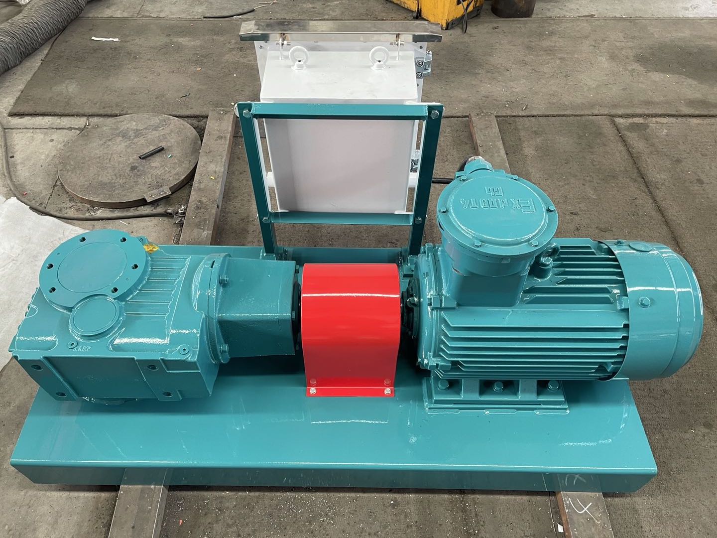
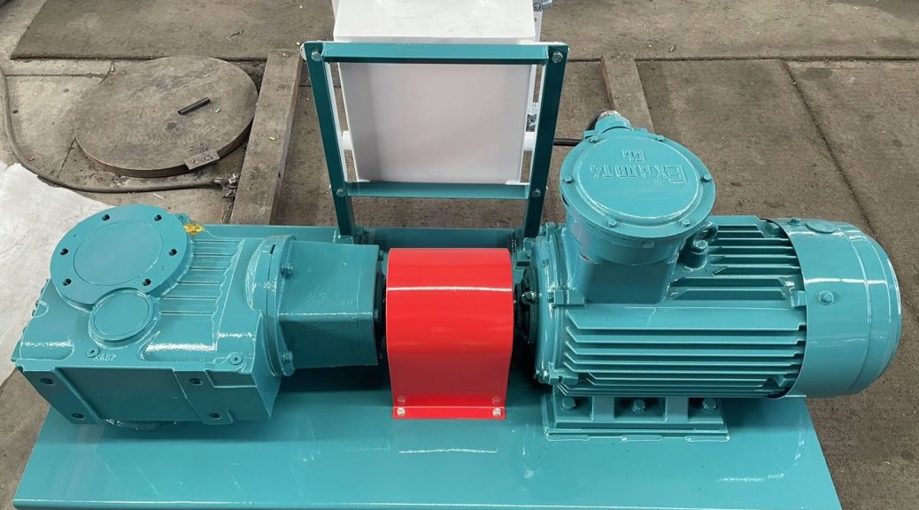
Mud agitators are fluid mixing equipment that keeps solids in drilling fluid suspending, no deposit in the mud tank bottom. It uses its impeller to agitate and mix the drilling mud to prevent solid particles from depositing in the tank or mud pit.
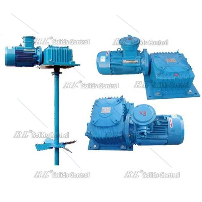
There were many types of mud agitator, depending on purpose demand, gearbox type, and working conditions. But the basic structure of the mud agitator is all the same: Motor, gearbox [Speed reducer], shaft, and impeller.
Yes. Some clients prefer the hydraulic drive for some specific use. Some clients need a vertical agitator. And some clients prefer the stainless steel shaft and impeller. Different applications and industries will request equipment much different If you have questions or demand on mud mixers, please let us know and we’ll help you to get the ideal solution.
For oil and gas drilling, there are different configurations on tanks number, tanks size, so it’s not easy to confirm. But we can take a system as an example. One mud system laying with 6 tanks, and tanks size are 9 m X 2.2 m X 2.3 m. The normal proposal is 3 sets of agitator per tank. But there is a shaker tank, then we deduct 1 set. So, probably we need 17 sets of the agitator. And the agitators are APM 7.5 driven by 7.5 kw motor.
After 5 days operation please discharge all of the oil out of the gearbox and clean gearbox feed clean lubrication oil in it. Then do the same work every 6 months.
The most important factor was the power of the mud agitator, 5.5 Kw agitator is cost far lower than 22 KW. There is apparently a different price between the explosion-proof type and Non-proof type. Higher explosion-proof grade means higher cost.
Motors are available with horizontal or vertical mounts. The motors generally have shafts that rotate much faster than the impellers need to rotate. A large gearbox, or gear reducer, used to turn the shaft, is mounted at the end of the motor. The motor size depends upon the diameter of the impeller blades and the density of the slurry.
Worm gearbox type mud agitator is a common type, durable, and easy maintenance. But its efficiency lower than the bevel gearbox. so bevel gearboxes are generally more expensive than worm gearboxes for the same HP and gear ratios. Helical-worm and helical-bevel are advanced generation type of worm and bevel gearbox. They produce less vibration and noise. The planetary gearbox is mainly used in vertical agitator.
canted blade, and proprietary. Generally, Materials determine the price of shaft and impeller. Stainless steel is more expensive than common carbon steel.
When you need to gain rapid access to the essential wholesale mud agitator 15kw supplies that your business relies on, head to Alibaba.com where you"ll find thousands of Chinese wholesalers ready to provide the equipment, materials, consumables and products that you need to run your business. From mud agitator 15kw supplies that cover all technical specifications through to associated products and office consumables, you can buy everything that your business needs in one place at Alibaba.com.
Simply use the search filters and categories to swiftly find details of mud agitator 15kw prices, specifications, order volumes, lead times, discounting arrangements and more. See what other customers thought of individual wholesalers with the customer review feature and see images of operations, markets served and more. You can even chat instantly with sales and support or send an email at any time of day.
Ready to make your mud agitator 15kw order? Just do so in a few clicks in your private account area and you"ll receive regular updates on your shipment so that you know exactly where it"s at in the world until it arrives at your business! It"s swift, convenient and cost-effective to shop at Alibaba.com where you"ll find everything that your business needs to operate smoothly and without delay.

M-I SWACO became a Schlumberger company in 2010. Innovative drilling fluid engineers are at the company"s core, helping oil and gas operators increase efficiency and lower costs. We do this by developing drilling fluid systems and additives that accommodate a wide range of drilling environments and demanding applications—including HPHT, deep water and ultradeep water, shale gas, heavy oil, depleted wells, and more.
Specialized additives complement the efficiencies of our advanced drilling fluid systems by targeting performance-hindering downhole conditions, eliminating or minimizing the problems that drive up costs and threaten drilling programs. For example, we were the first to introduce cost-effective, high-efficiency micronized barite technology to water- and oil-based drilling fluids.
Our base fluids and additives are tailored for specific well construction applications. Custom formulation helps you maintain wellbore stability, optimize ROP, and increase overall drilling efficiency while reducing NPT and minimizing HSE footprint.

Ablard P, Bell C, Cook D, Fornasier I, Poyet J-P, Sharma S, Fielding K, Lawton G, Haines G, Herkommer MA, Mccarthy K, Radakovic M, Umar L: The expanding role of Mud logging. Oilf Rev. 2012, 24: 24-41.
Hammerschmidt S, Toczko S, Kubo Y, Wiersberg T, Fuchida S, Kopf A, Hirose T, Saffer D, Tobin H, the Expedition 348 Scientists: Influence of drilling operations on drilling mud gas monitoring during IODP Exp. 338 and 348 [abstract]. Geophysical Research Abstracts EGU General Assembly 2014, 16E:EGU2014-5904. http://meetingorganizer.copernicus.org/EGU2014/EGU2014-5904.pdf.
Aquilina L, Baubron J-C, Defoix D, Dégranges P, Disnar J-R, Marty B, Robé M-C: Characterization of gases in sedimentary formations through monitoring during drilling and core leaching (Balazuc borehole, deep geology of France programme). Appl Geochem. 1998, 13: 673-686. 10.1016/S0883-2927(98)00008-0.
Ellis L, Berkman T, Uchytil S, Dzou L: Integration of mud gas isotope logging (MGIL) with field appraisal at horn mountain field, deepwater gulf of Mexico. J Pet Sci Eng. 2007, 58: 443-463. 10.1016/j.petrol.2007.03.001.
Erzinger J, Wiersberg T, Dahms E: Real-time mud gas logging during drilling of the SAFOD Pilot Hole in Parkfield, CA. Geophys Res Lett 2004, 31:L15S18.,
Wiersberg T, Erzinger J: A helium isotope cross-section study through the San Andreas Fault at seismogenic depths. Geochem Geophys Geosyst 2007, 8:Q01002.,
Wiersberg T, Erzinger J: Origin and spatial distribution of gas at seismogenic depths of the San Andreas Fault from drill-mud gas analysis. Appl Geochemistry. 2008, 23: 1675-1690. 10.1016/j.apgeochem.2008.01.012.
Wiersberg T, Erzinger J: Chemical and isotope compositions of drilling mud gas from the San Andreas Fault Observatory at Depth (SAFOD) boreholes: Implications on gas migration and the permeability structure of the San Andreas Fault. Chem Geol. 2011, 284: 148-159. 10.1016/j.chemgeo.2011.02.016.
Expedition 319 Scientists: Site C0009. Proc IODP 319. Edited by: Saffer D, McNeill L, Byrne T, Araki E, Toczko S, Eguchi N, Takahashi K. 2010, Integrated Ocean Drilling Program Management International, Inc, Tokyo, doi:10.2204/iodp.proc.319.104.2010
Inagaki F, Hinrichs K-U, Kubo Y, the Expedition 337 Scientists: Deep coalbed biosphere off Shimokita - microbial processes and hydrocarbon system associated with deeply buried coalbed in the ocean. IODP Prel Report 2013, 337. doi:10.2204/iodp.pr.337.2012.,
Screaton EJ, Kimura G, Curewitz D, the Expedition 316 Scientists: Expedition 316 Summary. Proc IODP 316. Edited by: Kinoshita M, Tobin H, Ashi J, Kimura G, Lallemant S, Screaton EJ, Curewitz D, Masago H, Moe KT. 2009, Integrated Ocean Drilling Program Management International, Inc, Washington D.C., doi:10.2204/iodp.proc.314315316.131.2009
Miyazaki S, Heki K: Crustal velocity field of southwest Japan: subduction and arc-arc collision. J Geophys Res. 2001, 106: 4305-4326. 10.1029/2000JB900312.
Okino K, Ohara Y, Kasuga S, Kato Y: The Philippine Sea: New survey results reveal the structure and the history of the marginal basins. Geophys Res Lett. 1999, 26: 2287-2290. 10.1029/1999GL900537.
Taira A, Hill I, Firth J, Berner U, Brückmann W, Byrne T, Chabernaud T, Fisher A, Foucher J-P, Gamo T, Gieskes J, Hyndman R, Karig D, Kastner M, Kato Y, Lallemant S, Lu R, Maltman A, Moore G, Moran K, Olaffson G, Owens W, Pickering K, Siena F, Taylor E, Underwood M, Wilkinson C, Yamano M, Zhang J: Sediment deformation and hydrogeology of the Nankai Trough accretionary prism: Synthesis of shipboard results of ODP Leg 131. Earth Planet Sci Lett. 1992, 109: 431-450. 10.1016/0012-821X(92)90104-4.
Kimura G, Hashimoto Y, Kitamura Y, Yamaguchi A, Koge H: Middle Miocene swift migration of the TTT triple junction and rapid crustal growth in southwest Japan — a review. Tectonics. 2014, 33: 1219-1238. 10.1002/2014TC003531. doi:10.1002/2014TC003531
Strasser M, Moore GF, Kimura G, Kitamura Y, Kopf AJ, Lallemant S, Park J-O, Screaton EJ, Su X, Underwood MB, Zhao X: Origin and evolution of a splay fault in the Nankai accretionary wedge. Nat Geosci. 2009, 2: 648-652. 10.1038/ngeo609.
Expedition 315 Scientists: Site C0002. Proc IODP 314/315/316. Edited by: Kinoshita M, Tobin H, Ashi J, Kimura G, Lallemant S, Screaton EJ, Curewitz D, Masago H, Moe KT. 2009, Integrated Ocean Drilling Program Management International, Inc, Washington D.C., doi:10.2204/iodp.proc.314315316.124.2009
Strasser M, Dugan B, Kanagawa K, Moore GF, Toczko S, Maeda L, the Expedition 338 Scientists: Site C0002 . Proc IODP 338. Edited by: Strasser M, Dugan B, Kanagawa K, Moore GF, Toczko S, Maeda L. 2014, Integrated Ocean Drilling Program Management International, Inc, Tokyo, doi:10.2204/iodp.proc.338.103.2014,
Scientists E 348, Participants S: Expedition 348 preliminary report NanTroSEIZE stage 3: NanTroSEIZE plate boundary deep riser 3. IODP Prelim Rep 2014, 348:71.,
Strasser M, Dugan B, Kanagawa K, Moore GF, Toczko S, Maeda L, the Expedition 338 Scientists: Methods. Proc IODP 338. Edited by: Strasser M, Dugan B, Kanagawa K, Moore GF, Toczko S, Maeda L. 2014, Integrated Ocean Drilling Program Management International, Inc, Tokyo, doi:10.2204/iodp.proc.338.102.2014
Whiticar MJ: Correlation of Natural Gases with Their Sources. The Petroleum System - From Source to Trap. Edited by: Magoon L, Dow W. 1994, AAPG, Tulsa, Oklahoma, USA, 261-283.
Bernard BB, Brooks JM, Sackett WM: Light hydrocarbons in recent Texas continental shelf and slope sediments. J Geophys Res Ocean. 1978, 83: 4053-4061. 10.1029/JC083iC08p04053.
Prinzhofer A, Mello MR, Takaki T: Geochemical characterization of natural Gas: a physical multivariable approach and its applications in maturity and migration estimates. Am Assoc Pet Geol Bull. 2000, 84: 1152-1172.
Dessay J, Torres O, Sharma S: Real Time Formation Characterization from Advanced Mud Gas Analyses for Improved Geological Operations Decisions [extended abstract]. In 73rd EAGE Conf Exhib. Vienna, Austria: 2011. abstract # DO22, doi:10.3997/2214-4609.20149082.
Haworth J, Sellens M, Whittaker A: Interpretation of hydrocarbon shows using light ( C1–C5) hydrocarbon gases from Mud-Log data. Am Assoc Pet Geol Bull. 1985, 69: 1305-1310.
Dhima A, de Hemptinne J-C, Moracchini G: Solubility of light hydrocarbons and their mixtures in pure water under high pressure. Fluid Phase Equilib. 1998, 145: 129-150. 10.1016/S0378-3812(97)00211-2.
Chapoy A, Mokraoui S, Valtz A, Richon D, Mohammadi AH, Tohidi B: Solubility measurement and modeling for the system propane–water from 277.62 to 368.16 K. Fluid Phase Equilib. 2004, 226: 213-220. 10.1016/j.fluid.2004.08.040.
Reddy CM, Arey JS, Seewald JS, Sylva SP, Lemkau KL, Nelson RK, Carmichael CA, McIntyre CP, Fenwick J, Ventura GT, Van Mooy BAS, Camilli R: Composition and fate of gas and oil released to the water column during the deepwater horizon oil spill. Proc Natl Acad Sci. 2012, 109: 20229-20234. 10.1073/pnas.1101242108.
James AT: Correlation of natural gas by use of carbon isotopic distribution between hydrocarbon components. Am Assoc Pet Geol Bull. 1983, 67: 1176-1191.
Abrams MA: Significance of hydrocarbon seepage relative to petroleum generation and entrapment. Mar Pet Geol. 2005, 22: 457-477. 10.1016/j.marpetgeo.2004.08.003.
Schoell M: The hydrogen and carbon isotopic composition of methane from natural gases of various origins. Geochim Cosmochim Acta. 1980, 44: 649-661. 10.1016/0016-7037(80)90155-6.
Whiticar MJ: Carbon and hydrogen isotope systematics of bacterial formation and oxidation of methane. Chem Geol. 1999, 161: 291-314. 10.1016/S0009-2541(99)00092-3.
Heuer VB, Pohlman JW, Torres ME, Elvert M, Hinrichs K-U: The stable carbon isotope biogeochemistry of acetate and other dissolved carbon species in deep subseafloor sediments at the northern Cascadia Margin. Geochim Cosmochim Acta. 2009, 73: 3323-3336. 10.1016/j.gca.2009.03.001.
Waples D: Time and temperature in petroleum formation: application of Lopatin’s method to petroleum exploration. Am Assoc Pet Geol Bull. 1980, 64: 916-926.
Harris RN, Schmidt-Schierhorn F, Spinelli G: Heat flow along the NanTroSEIZE transect: Results from IODP Expeditions 315 and 316 offshore the Kii Peninsula, Japan. Geochem Geophys Geosystems 2011, 12:Q0AD16.,
Underwood MB, Saito S, Kubo Y, the Expedition 322 Scientists: Expedition 322 Summary. Proc. IODP 322. Edited by: Saito S, Underwood MB, Kubo Y. 2010, Integrated Ocean Drilling Program Management International, Inc, Tokyo, doi:10.2204/iodp.proc.322.101.2010
Marcaillou B, Henry P, Kinoshita M, Kanamatsu T, Screaton E, Daigle H, Harcouët-Menou V, Lee Y, Matsubayashi O, Kyaw Thu M, Kodaira S, Yamano M, Expedition 333 Scientists: Seismogenic zone temperatures and heat-flow anomalies in the Tonankai margin segment based on temperature data from IODP expedition 333 and thermal model. Earth Planet Sci Lett. 2012, 349–350: 171-185. 10.1016/j.epsl.2012.06.048.
Prinzhofer A, Pernaton É: Isotopically light methane in natural gas: bacterial imprint or diffusive fractionation?. Chem Geol. 1997, 142: 193-200. 10.1016/S0009-2541(97)00082-X.

Lonnie L Thompson PatentedSept. a, 1942 UNITED; STATES .QPATENT OF ICE SAMPLING DEVICE Lonnie L. Thompson, Iowa Park, Tex, assignor to Thompson Tool Com .Tex., a corporation of Texas,
This invention relates to an improvement in sampling devices of the type used primarily in connection with rotary welljdrilling rigs which Fig. 9 is a side elevation thereof with parts broken away;
" Fig. 7 of. the drawings shows generally a rotary The primary object of this invention is to provide for automatically obtaining samples of the formation as the well is drilled and depositing these samples in a receptacle for further inspectionand analysis. By the use of .this invention; the. human element is eliminated in the securing of these samples, as they ar automatically deposited in a container from which they may be removed and inspected later at will.
While the drawings illustrate a preferred embodiment of the invention, ttogether with modiflcations thereof, it is to be understood that the design may be varied and changes made in the minor details of construction to meet specific needs and requirements, within the scope of the invention as claimed, without departing from the spirit thereof.
" Fig. 6 is a vertical section through a bucket for catching sample formations Fig. 7 is a diagrammatic perspective view of a rotary rig having a shale separator and formation sampling device associated therewith;
out through a pipe 4 to the rig 1, having a rotary table 2 from which is suspended a rotary drill unit having provision for circulating fluid or mud -therethrough, thence i P us lly passing through a shale separator 5 for removing foreign substances therefrom.
Instead of catching some of this recirculated fluid from the well in a bucket, to obtain samples of theformation, as heretofore, I have provided a sampling device 6 associated with th "shale separator 5 or in the pipe lto obtain automatically samples of"the earth formation in the fluid flowing from the well through the pipe 4.
The construction of the preferred embodiment -.of the sampling device 6 is shown more particularly in Figs. 1 to 3, in which the numeral 1 designates a housing of the shale separator which encases a paddle wheel 8, which paddle wheel 8 serves as a motivating element to drive the shale separator and the mechanism of the sampling device. The drilling fluid enters housing I from the pipe 4 by means of inlet pipe 9 and passes therethrough in the direction indicated by the arrows, thence directly into the cylinder III of the shale separator. This in turn rotates the paddle wheel or impeller 8 in the direction indicated by the arrow in Fig. 2. The pipe 9 and cylinder II) are in axial aligmnent and are connected with respective opposite sides of the housing 1. The paddle wheel 8 is secured to a shaft ll journaled in opposite sides of the housing I, with opposite ends projecting outwardly from said housing, one end having driving connection with the cylinder l0 throughdriving means H, while the other end drives sampling mechanism, as hereinafter described.
Spaced at one side from the housing I isa casing 12 having an inlet tube l3 extending from one side of the casing l2 to the inlet pipe 9 with e which it communicates and which directs fluid from the inlet pipe 9 into .the-casing-IZ, and said casing I2 has an outlet tube It and which the fluid to pass outward from the casthe invention shown end of the outlet tube the inner end of the fluid to rise in the permits the heavy particles indicative of the earth formation to settle to the bottom of the casing l2.
The shaft extends into the casing I2 and carries thereon a sprocket I! over which a sprocket chain i6 extends, passing also over idle sprockets i1 and I8, operating in the direction indicated by the arrows in Fig. 2. The chain I6 carries a cup IS, in position to dip into the bottom of the casing l2 in passing around the sprocket l8 and scoop up the particles of earth formation that have settled to the bottom of said casing from the fluid flowing therethrough. The cup I! then passes around the sprocket H to dump the scooped material through an opening 20 in the bottom portion of the casing i2. Only one cup I9 is shown, but additional cups may be used if desired, although it is preferred that they should be so spaced and operated at such slow speed as to permit the formation particles to settle in the casing l2 between successive dips of the cup or cups.
Each of the sprockets l1 and It may be journaled in the free end of a U-shaped frame 2|, as shown in Figs. 10 and 13, which frame is pivotally supported at 22 on the outer wall 23 of the casing I2, for adjustment of the sprockets and regulation of the travel of the chain l6 and of the tightness thereof. To permit such adjustment and to hold each frame 2| in a set position, said frame has an arcuate slot 24 therein receiving a fastening bolt 25 extending through v the wall 23" of the casing l2.
The cup 19 is constructed generally in the shape of a bucket for dipping up a sample of the material in the bottom of the casing l2, and as shown in Fig. 14, the cup I! preferably is provided with one or more holes 26 in the bottom thereof to permit the escape of the liquid from the scooped up material during the upward travel of the chain It to the point of discharge. These holes 26 are preferably covered with screens when of appreciable size, to prevent the escape of the cuttings that have been obtained from the well.
As shown in Fig. 10, a wedge-shaped deflector 21 is pivotally supported at 24 on the casing l2, at a point immediately beneath: the opening 20 in the casing in position for discharge of the material from the cup l9 through said opening directly onto the deflector 21. The deiiector is arranged with its apex turned upwardly so .as to divert the material to one side or the other thereof. To regulate .the position of the deflector 21, it is provided with an arm 29 cooperating with a scale 30 provided on the front wall 23 of the casing l2.
At one side of the deflector 21 is a receptacle 3|, shown in detail in Fig. 6, provided with a ball 32 adapted to removably engage a hook 23 on the casing |2 for supporting the receptacle 2| in proper position to receive the cuttings and particles discharged by the cup I! when the defiector 21 is turned to a position where it will directsaid material into the receptacle ll. The deflector 21 may be adjusted so as to direct any desired proportion-of the material into the receptacle 3| as may be desired to prevent the filling of the receptacle too quickly, and the remainder of the material deflected to the opposite side of the deflector 21 may be discharged into the usual sacks or otherwise disposed of.
The receptacle 2| (Fig. 6) has a series of perforations 34 arranged vertically thereof and covered by a wire screen 45 which allows further draining off of the liquid and circulation of the air therethrough to facilitate drying of the sample into molded and compact form substantially as shown at S in Fig. 5. When the receptacle 2| has been fllled to the desired height it may be removed from the sampling device and replaced by an empty receptacle and the filled one set aside for drying and molding of the sample therein. After the sample has dried sumciently, it may be readily removed from the receptacle by sliding it out, and to facilitate this removal, the receptacle 3| is provided with a lifting wire 26 extending upwardly approximately at the axis thereof, which wire 38 carries a washer 31 at the lower end thereof normally resting at the bot tom of the receptacle and tending to hold the wire in its central position in the receptacle. This wire 36 serves also as a stiffening element in the molded samples to prevent accidental breaking thereof since it becomes embedded in the sample as the latter sets.
In the form of the invention shown in Figs. 1, 2 and 3, the bucket I9 discharges the scooped up material into a chute 4| welded to a portion of the casing l2 and extending transversely thereof within an enlargement 43 thereof. The chute 4| projects downwardly in an inclined direction through the opening 20 and has. a notch or hook 44 at the lower end thereof that receives the bail of the receptacle 3|, as shown in Figs. 2 and 3, so as to suspend said receptacle from the chute 4|.
The shaft 42. carries a screen tumbler 45 rotatably mounted within the enlargement 43 of the casing and open at opposite ends, being supported on the shaft by spiders arranged at suitable intervals therein and attached to the screen of the tumbler. The screen tumbler 45 has a spiral conveyor 46 extending lengthwise therein adjacent the inner periphery of the screen for feeding material lengthwise of the tumbler from the intake to the discharge ends thereof. This spiral conveyor 46 is supported also at intervals on the shaft 42 by spiders or other means. A chute 41 welded to a portion of the casing H, has one end arranged in position to receive material from the bucket l9 at the point of discharge thereof and the opposite end of said chute is directed into the tumbler 45, so that part of the material scooped up by the bucket is directed into the tumbler 45 and the remainder is directed by the chute 4| into the receptacle 3|.
The tumbler 45 is rotated by the shaft 42, which is driven by belt or other gearing 48 from the shaft Thus when material is directed into the tumbler 45 by the chute 41, it is fed gradually through the tumbler and discharged at the opposite end thereof into a receptacle 3|, shown in Figs. 1 and 3, which is similar in construction to the receptacle 3|, shown in detail in Fig. 6, and which has been described above.
spray jets of water onto the tumbler 45, thereby automatically washing the mud from the material passing therethrough. This spray is con-" trolled by a valve 50, as shown in Fig. 1, so as to I discontinue the washing operation whenever desired. One end of the spray pipe 49 is directed at over the cup 19 when the latter is in the posi-" tion shown in Fig. 2, so as to wash the cup clean each time that it reaches this position and causing the sample to drop readily therefrom into the respective chutes.
In this way, it is possible to obtain two types of samples simultaneously, one including the mud from the well with the formation particles being discharged directly into the receptacle 3!, while the other sample is washed free of mud by the spray pipe 49 that leaves only the earth formation without mud or dirt, and this is collected in the receptacle 3|. The mud washed from the sample will flow downward through the casing l2, being discharged through the outlet pipe I4. I
A further modification of the invention is shown in Figs. 8 and 9, in which the conveyor chain and-cup are not used, but this employs a tumbler 52, which is joumaled on a shaft 53 mounted in a trough 54 beside the shale separator and driven therefrom by a belt 55. The trough 54 has an inclined bottom and the tumbler 52 has a spiral screw conveyor 56 therein for directing the sample forwardly through the tumbler in the manner described above in connection with Figs. 1 to 3, the sample being discharged from a lip 57 into a receptacle 3! removably supported at the discharge end of the trough 5d. Tumbler 52 has a spray pipe 58 extending thereover to wash the mud from the sample, as described above, but if it is desired to obtain a sample with the mud, this may be done by stopping the washing action and permitting the screw conveyor 56 to direct the entire material into the receptacle. The mud from the well enters the open end of the tumbler 52, di-
" rectly from the inlet pipe l3, while the mud from the trough 54! is discharged through the pipe it into the shale separator, directly into the bottom trough thereof.
It will be apparent that the forms of the invention shown in Figs. 1, 2, 3, 8 and 9 are utilized in association with a shale operator either of the type illustrated or of any suitable type, while the form of the invention shown in Figs. 10 to 12 operates independently of a shale separator directly in the discharge pipe i from the well.
these covers being hinged or otherwise removably secured thereto to facilitate gaining access to the interiors thereof. These covers 38 and 39 serve the additional useful purpose of aiding in determining the presence of gas because if the formation drilled contains gas the housing and casing serve as traps for the same, and this may be detected merely upon raising the covers and making the usual tests.
The operation of the sampling device will be obvious from the foregoing description, but it may be pointed out that an important characteristic of this invention is the operation of the sampling. device automatically by the mud and fluid being pumped out of the well in the course of the drilling operation and utilizing"the force of this fluid for the accumulation of a sample of the formation encountered in the drilling. The accumulation of this sample automatically in the manner described enables the operator to obtain an accurate sample truly representative of the formation in thewell. Any desired proportion ofthe fluid passing through the pipe 4 may be diverted into the casing H to obtain a sample therefrom, a butterfly valve 40" being provided in the tube l3, as shown in Figs. 2 and 10, to control the flow therethrough into the casing l2.
1. The combination of well drilling apparatus having a discharge pipe for drilling fluid, and a sampling device operatively connected with said discharge pipe comprising means for diverting a portion of the fluid from the discharge pipe, a sample receptacle, means for separating solid particles of earth formation fromsaid diverted fluid and directing the separated solids into said receptacle, and fluid driven means in the path of flow from said pipe for operating said separating means.
2. A sampling device comprising a casing having means for directing fluid thereinto for settling solid particles from said fluid, a receptacle associated with the casing, an endless device having a bucket carried-thereby for dipping settled particles in the casingand directing the sameinto the receptacle, a rotatable tumbling device associated with the casing, means for directing particles from said bucket; into said tumbling device, washing means for said tumbling device, and a second receptacle in position to receive particles from the tumbling device.
3. In apparatus for obtaining samples of cuttings in mud laden fluids used in well drilling, the combination with well drilling apparatus having a well casing and a fluid discharge pipe connected therewith for directing mud-laden fluids from the well, of a sampling device comprising a rotary screen having open opposite ends, a conduit having one end connected with said discharge pipe and having the other end thereof arranged to direct a proportionate share of the drilling fluid from the discharge pipe into one end of said screen, a receptacle arranged at the opposite end of the rotary screen in position to receive screenedsolids therefrom, said receptacle being constructed to retain the solids therein and to screen liquid therefrom, and fluid driven means in the path of flow from the fluid discharge pipe for operating said screen.
. combination with well drilling apparatus having a well casing and a fluid discharge pipe connect= ed therewith for directing mud-laden fluids from the Well, of a sampling device comprising 8. cas ing, a rotary screen mounted in the casing, means for directing a proportionate share of the drilling fluid from the pipe to the casing, means for directing said fluid into one end of the screen for screening solids from the fluid, a container connected, with the screen casing at the opposite end of the screen to receive the solids therefrom,

This website is using a security service to protect itself from online attacks. The action you just performed triggered the security solution. There are several actions that could trigger this block including submitting a certain word or phrase, a SQL command or malformed data.


 8613371530291