
triplex mud pump output calculator for sale

Pump Output per Stroke (PO): The calculator returns the pump output per stroke in barrels (bbl). However this can be automatically converted to other volume units (e.g. gallons or liters) via the pull-down menu.
A triplex mud (or slush) pump has three horizontal plungers (cylinders) driven off of one crankshaft. Triplex mud pumps are often used for oil drilling.

Rig pump output, normally in volume per stroke, of mud pumps on the rig is one of important figures that we really need to know because we will use pump out put figures to calculate many parameters such as bottom up strokes, wash out depth, tracking drilling fluid, etc. In this post, you will learn how to calculate pump out put for triplex pump and duplex pump in bothOilfield and Metric Unit.

NOTE: Max RPM in the above equation varies according to type of pump, size of stroke, and other variables. Duplex pumps often run about 100 RPM Max. while triplex pumps will run somewhere between 100 RPM Max and 400 RPM Max.
I have a reciprocating pump and I know what my max rated rod load is (in foot pounds). I also know what size plunger size my pump has. What PSI will my pump produce?
Specific Gravity is used when sizing a centrifugal pump. Liquids with a specific gravity greater than 1.0 are heavier than water and conversely, liquids with a specific gravity lower than 1.0 are lighter weight than water and will generally float on water.

To install Triplex Pump Output bbl/stk on your Android device, just click the green Continue To App button above to start the installation process. The app is listed on our website since 2013-09-06 and was downloaded 22 times. We have already checked if the download link is safe, however for your own protection we recommend that you scan the downloaded app with your antivirus. Your antivirus may detect the Triplex Pump Output bbl/stk as malware as malware if the download link to com.afislite.triplexpump is broken.
Once the Triplex Pump Output bbl/stk is shown in the Google Play listing of your Android device, you can start its download and installation. Tap on the Install button located below the search bar and to the right of the app icon.
Triplex Pump Output bbl/stk will be downloaded onto your device, displaying a progress. Once the download completes, the installation will start and you"ll get a notification after the installation is finished.

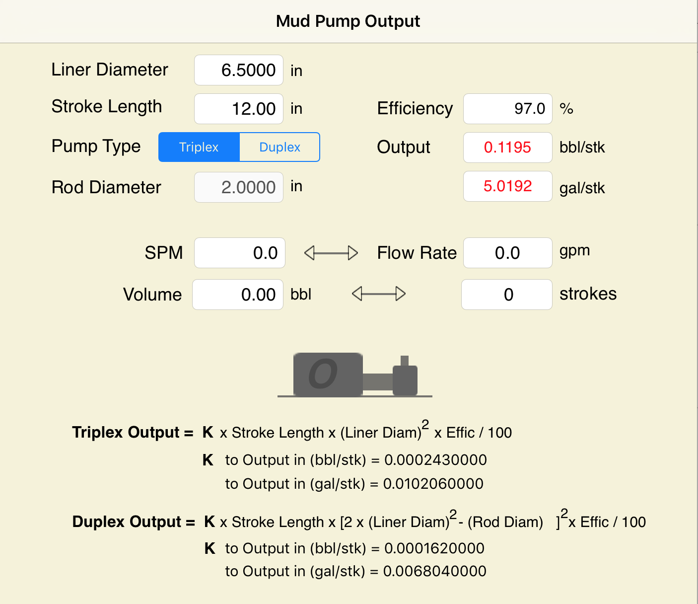
Oil and Gas drilling process - Pupm output for Triplex and Duplex pumpsTriplex Pump Formula 1 PO, bbl/stk = 0.000243 x ( in) E.xample: Determine the pump output, bbl/stk, at 100% efficiency for a 7" by 12". triplex pump: PO @ 100%,= 0.000243 x 7 x12 PO @ 100% = 0.142884bbl/stk Adjust the pump output for 95% efficiency: Decimal equivalent = 95 + 100 = 0.95 PO @ 95% = 0.142884bbl/stk x 0.95 PO @ 95% = 0.13574bbl/stk Formula 2 PO, gpm = [3(D x 0.7854)S]0.00411 x SPM where D = liner diameter, in. S = stroke length, in. SPM = strokes per minute Determine the pump output, gpm, for a 7" by 12". triplex pump at 80 strokes per minute: PO, gpm = [3(7 x 0.7854) 1210.00411 x 80 PO, gpm = 1385.4456 x 0.00411 x 80 PO = 455.5 gpm
Example:Duplex Pump Formula 1 0.000324 x (liner diameter, in) x ( stroke lengh, in) = ________ bbl/stk -0.000162 x (rod diameter, in) x ( stroke lengh, in) = ________ bbl/stk Pump out put @ 100% eff = ________bbl/stk Example: Determine the output, bbl/stk, of a 5 1/2" by 14" duplex pump at 100% efficiency. Rod diameter = 2.0": 0.000324 x 5.5 x 14 = 0.137214bbl/stk -0.000162 x 2.0 x 14 = 0.009072bbl/stk Pump output @ 100% eff. = 0.128142bbl/stk Adjust pump output for 85% efficiency: Decimal equivalent = 85 100 = 0.85 PO@85%)= 0.128142bbl/stk x 0.85 PO@ 85% = 0.10892bbl/stk Formula 2
PO. bbl/stk = 0.000162 x S[2(D) - d] where S = stroke length, in. D = liner diameter, in. d = rod diameter, in. Example: Determine the output, bbl/stk, of a 5 1/2". by 14". duplex pump @ 100% efficiency. Rod diameter = 2.0in.: PO@100%=0.000162 x 14 x [ 2 (5.5) - 2 ] PO @ 100%)= 0.000162 x 14 x 56.5 PO@ 100%)= 0.128142bbl/stk Adjust pump output for 85% efficiency: PO@85%,= 0.128142bb/stkx 0.85 PO@8.5%= 0.10892bbl/stk Metric calculation Pump output, liter/min = pump output. liter/stk x pump speed, spm. S.I. units calculation Pump output, m/min = pump output, liter/stk x pump speed, spm. Mud Pumps Mud pumps drive the mud around the drilling system. Depending on liner size availability they can be set up to provide high pressure and low flow rate, or low pressure and high flow rate. Analysis of the application and running the Drill Bits hydraulics program will indicate which liners to recommend. Finding the specification of the mud pumps allows flow rate to be calculated from pump stroke rate, SPM. Information requiredo Pump manufacturer o Number of pumps o Liner size and gallons per revolution Weight As a drill bit cutting structure wears more weight will be required to achieve the same RoP in a homogenous formation. PDC wear flats, worn inserts and worn milled tooth teeth will make the bit drill less efficiently. Increase weight in increments of 2,000lbs approx. In general, weight should be applied before excessive rotary speed so that the cutting structure maintains a significant depth of cut to stabilise the bit and prevent whirl. If downhole weight measurements are available they can be used in combination with surface measurements to gain a more accurate representation of what is happening in the well bore.
This approach works well but relying on a printed reference is not without the risk since the wrong value can still be selected from the fine print of a reference table, or the reference document can be damaged or lost (e.g., dropped in the mud pit) altogether.
The intermediate casing can be sealed using the pressure grouting technique (Figure 3) to pump cement slurry down through the drill pipe and out to the annulus through a float shoe (a drillable check valve connected to the base of the casing). The inside of the intermediate casing is kept full of water during the cement placement to equilibrate hydraulic pressures inside and outside the casing. After the intermediate casing is sealed with the pressure grouted cement, the float shoe can be drilled out and the borehole advanced for installation of the screen and filter pack in the lower part of the well.
There are several calculations that are commonly applied by drilling fluid engineers (mud engineers) to determine the time period required for the fluid to move from one location in the borehole to another. Some of the more common equations are described below.
The uphole velocity calculation provides a determination of the speed at which the drilling mud will flow as it moves up the borehole. For direct air rotary or reverse circulation drilling methods, the uphole velocity is high, so this calculation is generally applicable only for the direct mud-rotary drilling method. The formula for uphole velocity is:
We can calculate the bottoms-up time by using the uphole velocity formula with the borehole depth and drilling mud flow rate plugged in, but that flow rate is being generated by the mud pump, and positive displacement mud pumps (duplex or triplex) are almost never equipped with a flow meter. To determine the flow coming from the mud pump, we can use the formulas:
Remember the strokes are counted in both the forward and backward directions on a duplex pump, but only in the forward direction on a triplex pump. Drillers often have reference charts that provide oilfield barrels per stroke (bbl/stroke), which can be converted to gpm by timing the strokes per minute and converting barrels to gallons (1 barrel = 42 gallons).
A specified volume of drilling fluids (called a pill) can be circulated to a particular depth interval within the borehole (called spotting), so that the additives in the pill of drilling mud can address the borehole problem at a particular depth of the borehole. This is shown in Figure 6(C).
The calculation for time required to spot a pill of drillingfluid involves determining the pumping time (at the calculated flow rate) required to displace the fluid so that the drilling mud additives are located adjacent to the problematic interval. This approach is used by mud engineers to address problems such as lost circulation or stuck drill pipe.

We provide hydraulic components & repair services for industrial applications like paper mills, saw mills, steel mills, recycling plants, oil & gas applications and mobile applications, including construction, utility, mining, agricultural and marine equipment. This includes hydraulic pumps, motors, valves, servo/prop valves, PTOs, cylinders & parts.


 8613371530291