
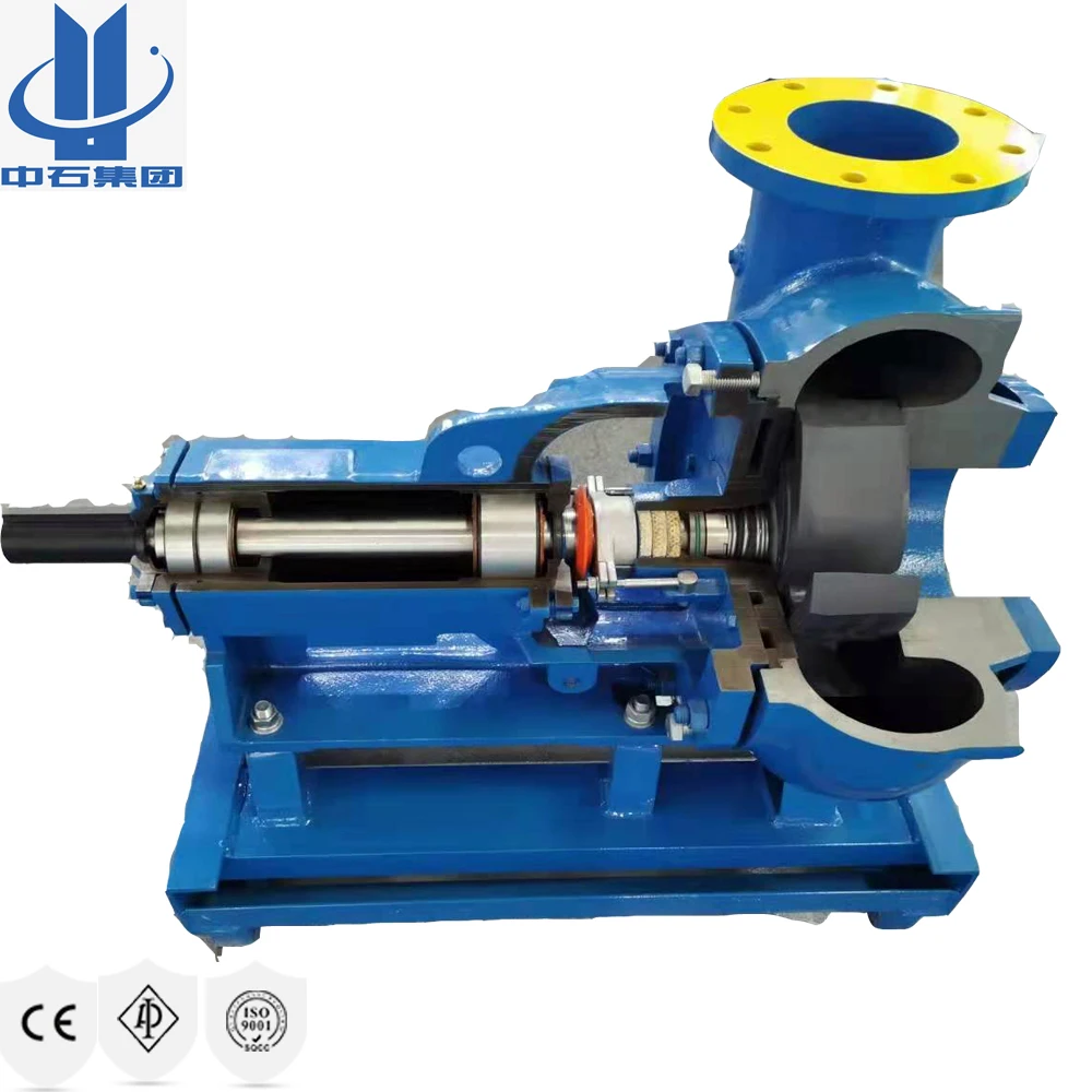
mission mud pump parts free sample

A part of National Oilwell Varco, the Mission line of centrifugal pumps are equipped with innovative features to match the demanding nature of routine, corrosive and abrasive applications. Because of the need for a low pressure mud system, Mission 1780 Type W centrifugal pumps were introduced in 1950s to replace duplex pumps. The aim was to apply a high quality centrifugal pump with concentric systems that allowed for abrasive fluids to be mixed and transferred thereby lowering the initial and maintenance costs of drilling. As a result, centrifugal pumps with low pressure mud systems such as Mission 1780 Type W became the industry standard.
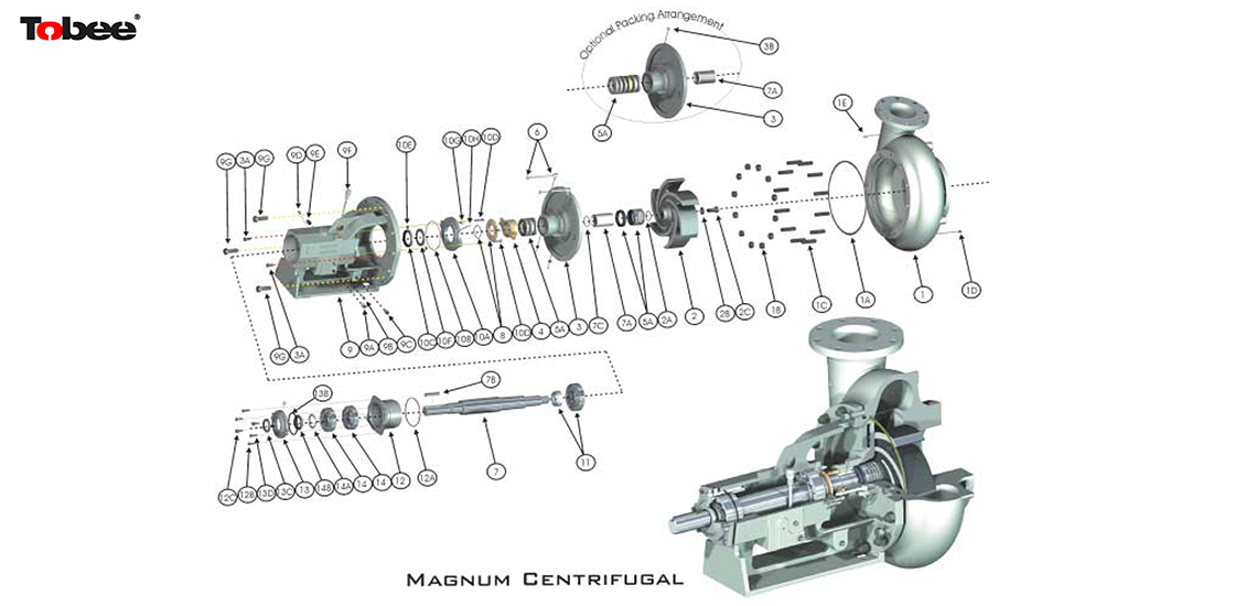
As well depths increased, so was the need for heavier mud weights and centrifugal pumps that could withstand greater horsepower load. This led to the launch of Mission Magnum- a centrifugal pump.
The Magnum has an open impeller design that contains wide-tipped vanes and a more tangential circumference of the suction allowing the pump to create a smoother flow pattern when handling abrasive fluids. The Magnum is available in Magnachrome™, hard iron, stainless steel, and aluminum bronze fluid ends. The pumps can be unitized with electric motors, diesel engines, and hydraulic motors (horizontal, vertical, or close-coupled configuration).
Our pump engineering experts have the industry knowledge to gladly assist you with any questions, concerns, or inquiries you may have regarding the pumps & pump parts we distribute @ 800.560.7867.
Healthy Urban Communities (HUC) in New England"s mission is to improve the environment and enhance the quality of life for urban residents throughout New England by building community capacity to assess and resolve environmental problems, achieving measurable and sustainable improvements in urban communities, and restoring and revitalizing neighborhoods for urban residents.

Willow pumps are unique because everything works inside the pump, inside your bra—no external tubes, cords, or dangling bottles. Plus, you don’t have to sacrifice performance. Willow® 3.0 and Willow Go™ offer hospital strength suction comparable to most double-electric and hospital-grade pumps - choose from seven levels of adjustable suction with Willow 3.0, or nine levels with Willow Go. They’re also easy to assemble and clean, and app connected.
Some women are able to obtain full or partial reimbursement for their Willow Pump and accessories through insurance. Use our Insurance Verifier to check your coverage and purchase your discounted pump.
As you navigate through this process, start with our guide on how to get a breast pump covered by your insurance. It gives you all the questions that you need to take to your insurance provider to understand how to obtain coverage and the costs involved.
Yes, you can. Simply pay for your breast pump, milk bags and accessories using your FSA/HSA debit card at checkout, or pay with another credit card and submit your receipt to your plan administrator for reimbursement.
*Promotional price valid for 20% off savings on the purchase of a Willow 3.0 Pump or Willow Go Pump and up to 20% savings on the purchase of select accessories. Offer ends on 2/27/2023 at 11:59 pm PT. Cannot be combined with any other offers or applied to previously placed orders. Cannot be applied to orders made through the Willow Insurance Coverage Program. We reserve the right to change these terms and conditions at any time.
Mission Pump Casing provided with replaceable casing wear pad on 3x2x13, 4x3x13, 5x4x14, 6x5x11, 6x5x14, 8x6x11, 8x6x14 and 10x8x14 Centrifugal Pumps.
Foreword… This manual contains instructions for the installation, operation and maintenance of the Mission Magnum I Pump.As pump service conditions and specifications vary considerably in pump installations, this manual cannot possiblycover every situation, but it is hoped that the information included will serve as a guide. Should questions arise, or start-up problems occur, it is suggested that you contact the Mission Pump Distributor or Salesman in your area.
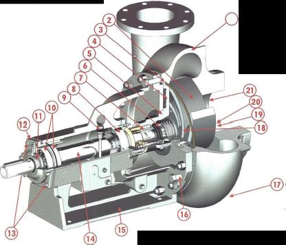
The Magnum I pump generation is an improved version of the older Mission S & W pump line. The Magnum I pumpis designed to give longer service life through heavier fluid end parts, heavier shaft bearings and reduced hydraulicloads.
There are many principles of proper pump installation and application as well as special considerations for theMagnum I design which, if followed, will further enhance the performance of your Magnum I pump.
I. GENERAL A. Initial Lubrication (Oil lubricated pumps)........................................................................ 10 B. Mechanical Seals ...........................................................................................................10 C. Start Up ..........................................................................................................................10
I. GENERAL A. Priming ...........................................................................................................................11 B. Maximum Operating Conditions .....................................................................................11 C. Pump Records................................................................................................................12 D. Pump Speed Limitations.................................................................................................12 E. Lubrication 1. Bearings ....................................................................................................................13 2. Stuffing Box ...............................................................................................................13 3. Lip Seals....................................................................................................................14
IV. ASSEMBLY A. General .......................................................................................................................... 17 B. Shaft and Bearing Sub-Assembly .................................................................................. 17 C. Power Frame Sub-Assembly ......................................................................................... 18 D. Assembly of Fluid End to Power Frame ......................................................................... 19 E. Packing the Pump .......................................................................................................... 19 F. Mechanical Seal ........................................................................................................ 20-21
Interchangeability between Magnum I horizontal centrifugal pumps and older W pumps will permit pumps of thesame nominal size to be interchanged using existing piping and bases.
The pump should be located near the liquid source so that the suction line may be short and direct. The pumpshould be located below the level of the liquid to eliminate the necessity of priming.
The foundation should be sufficiently rigid and substantial to absorb any vibration and to permanently support thebase plate at all points. A concrete foundation, poured on a solid footing of adequate thickness to support the pumpingunit, provides the most satisfactory foundation. The base plate should be installed in a level position. Figure 1 shows atypical arrangement for bolting channel bases.
The rugged design of the frame and the fluid end makes the Magnum I more tolerant of improper foundations thanmany other pumps. When fabricated skid bases are utilized, the foundation should be sufficiently rigid and leveledproperly to absorb any vibration and to permanently support the base at all points.
Good service life of the pump and driver depends upon good alignment through the flexible coupling. If the electricmotor was mounted at the factory, the pump and motor were in alignment when shipped. The alignment between thedriver and pump should be inspected after installation to ensure that transportation or other handling has notcaused misalignment of the unit. Poor alignment may cause failure of the coupling, pump, or motor bearings, or ofeither shaft.
The recommended procedure for coupling adjustment is by the use of a dial indicator, as illustrated in Figures 2and 3. The dial indicator is attached to one coupling half with the indicator button resting on the O.D. of the othercoupling half to measure offset misalignment. To measure angular misalignment, the indicator is positioned so that thebutton rests on the face, near the O.D., of the other coupling half. Rotate the shaft and dial indicator one full revolutionwhile the other shaft remains stationary and note the T.I.R. Unless otherwise specified by the coupling manufacturer,offset misalignment should be limited to 0.010 inches T.I.R. and angular misalignment should be limited to 0.005 inchesT.I.R. Adjust misalignment by loosening driver or pump mounting bolts and re-tightening or shimming as required.
Piping should be anchored independently of the pump and as near to it as possible. Pipe companion flanges should line up naturally with pump flanges. Do not draw the pipe to the pump with flange bolts.
Properly selected and installed suction piping is extremely important to eliminate vibration and cavitation in the pump. Vibration can cause packing problems, mechanical seal damage or undue bearing loads. The suction line should be equal to or larger than the pump suction.
The capacity of a centrifugal pump should never be adjusted by throttling the suction line. A positive shut-off valve of a type to cause minimum turbulence should be installed in the suction line to permit the closing of the line and removal of the pump for inspection and maintenance.
The suction line should have a straight section into the pump of a length equivalent to at least two (2) times its diameter; i.e., 4-inch suction; 8-inch straight run.
All piping should be independently supported and accurately aligned. The pump must not support the weight of the pipe or compensate for misalignment.
If operating conditions are not known with sufficient accuracy, it will be necessary to provide a throttle valve in the discharge line to ensure that the pump operates at the design point.
If the pump is connected to a pressurized system, it is important to install a check valve between the pump discharge and the throttling valve. The check valve will prevent back flow through the pump. Back flow may cause the impeller to become loose on the shaft. A loose impeller will likely result in mechanical damage and fluid leakage beneath the shaft sleeve.
Standard pumps are shipped with empty oil reservoirs. Oil must be added before operating the pump. Attachthe oiler to the bearing housing, fill the bottle with oil and place it in position. Refill the bottle until the bottle remains fullof oil. Oil should not be added to the reservoir except through the oiler bottle.
When mechanical seals are furnished, the description and identification is indicated on the order write-ups, whichare a part of the order acknowledgment, dimension print and the packing list. The seals are installed and adjusted at thefactory. To properly prepare the seal for operation, various cooling and flushing flows may have to be connected. Liquidfrom an outside source may be required. Connect necessary cooling and flushing flows to mechanical seal, be sure flowis turned on before starting the pump.
! WARNING ! WARNING ! WARNING !IT IS ABSOLUTELY ESSENTIAL THAT THE ROTATION OF THE MOTOR BE CHECKED BEFORE CONNECTINGTHE SHAFT COUPLING. INCORRECT ROTATION OF THE PUMP FOR EVEN A SHORT TIME WILL DISLODGETHE IMPELLER AND DAMAGE THE IMPELLER, SHAFT OR BEARING HOUSING. THE PUMP SHAFT MUST TURNCLOCKWISE WHEN VIEWED FROM THE MOTOR END.
1. Pump rotates freely by hand 2. Coupling aligned 3. Oiler full and oil level correct 4. Suction valve fully open 5. Pump and suction line full of fluid 6. Water to stuffing box or gland flush 7. Discharge valve slightly open
Vent air from suction line and fill with liquid. Start pump with discharge valve cracked open. After dischargepressure stabilizes, gradually open discharge valve to required position. If flow is lost, close discharge valve and wait afew seconds for discharge pressure to build.
Continued flow difficulty indicates an improper selection or installation. Running the pump too long with improperprime may destroy the sealing faces of the mechanical seal due to mechanical damage from pulsation and interferencebetween rotating and stationary components.
4. Cooling water through the lantern ring is required when the fluid being pumped is between 150ºF and 250ºF. In addition, it may be necessary to run water over the exposed shaft to prevent excessive heat at lip seals and bearings.
Maintain data cards or pump records whenever possible. This will provide ready access to information forordering spare parts and for evaluating pump and mechanical seal performance.
Bearings are prelubricated from the factory and in low speed, low temperature application may need no lubrication throughout the life of the pump. (RE: Ambient temperature of pumped fluids less than or equal to 1.2 specific gravity should not exceed 1150 to 1750 RPM.)
If the packing leakage is excessive, a thick water compatible pump grease should be used rather than the general purpose grease. In most cases, general purpose grease will be acceptable.
The inboard bearing cover is supplied with a zerk fitting between the 10 and 11 o’clock position facing the suction. This is designed to create a grease barrier between the inboard lip seals and should be greased prior to washdown and at least once a week with 5 shots of general purpose or water pump grease. (See Fig. 4, Pg. 12.)
4. Restrain the shaft (7) at the coupling end to prevent rotation while removing the impeller. NOTE: Mission Impeller Removal Wrench Part No. 20952 is very useful.
Put a block of wood or pipe, etc. against web between impeller vanes. Hit wooden block with sledge to turn impeller counterclockwise as viewed from suction end. If Mission Impeller Wrench is used, the wrench can be impacted against a solid surface using the impeller’s own weight to jar it loose.
8. Remove shaft sleeve (7A). A wedge may be driven between the end of the sleeve and shoulder on shaft to free the sleeve. If the pump has a mechanical seal that does not need to be replaced, care must be taken to avoid damaging or dropping the rotary seal ring (Item 4A on Figure 9, Pg. 25) when removing the sleeve.
All parts should be clean before assembly. This is especially important at retaining ring and O-Ring grooves,threads, gasket surfaces and bearings and bearing lubricated areas. Any burrs should be removed with crocus cloth.
7. Slip shaft sleeve seal (7C) onto the shaft and push it to the shoulder where the sleeve will seat. For pumps with a mechanical seal, see mechanical seal installation instructions in “Assembly” for assembling the remainder of the pump.
With the packing gland (4) in position, swing gland bolts into place. Tighten the gland lightly against the packingusing the gland bolt nuts. CAUTION: tighten gland against packing finger tight only. If packing is over tightenedit may be burned when the pump is started.
14. Attach gland bolts (6) to pump with nuts (6A). Start the gland bolt nuts. With the packing gland (4) in position, swing the gland bolts into place. Tighten gland bolt nuts lightly against the packing.
Arrangement for Magnum I Item Qty. Part Name Pumps in Severe Service 1 1 Stationary Seat 1A 1 Seat O-Ring 4A 1 Rotating Seal Ring Recommended Spare Parts 4B 1 Bellows Items 1, 4A, 4B, 4C, 5. 4C 1 Cage Assembly 5 3 Packing** See Dwg. 17538 for Subassembly Part Nos. and Stuffing Box 6 1 Spring Conversion Unit. 7A 1 Sleeve** 9 1 Spring Retainer 15 1 Spring Pin
Excessive Short Noise/ No Insufficient Insufficient IntermittentCauses Power Bearing Vibration Flow Flow Pressure Flow Required LifePump not primed X XSpeed too low X XExcessive discharge head X XInsufficient NPSH available X X X XImpeller clogged X X XWrong direction of rotation X XPlugged suction or discharge X X XlineFoot valve or suction line not X X Ximmersed deeply enoughImpeller damaged X X XShaft packing or seal defective X XImpeller diameter too small X XImpeller diameter too large XExcessive amount of air or gas X X Xin liquidSpeed too high X XTotal head lower than design XSpecific gravity or viscosity too X X XhighBent shaft X X XImproper electric motor wiring Xor voltageRotating elements bind X X XLeaky suction line or shaft seal X X XMisalignment X X XBearings worn X XImpeller out of balance X XSuction or discharge piping not XanchoredImproper foundation XInsufficient discharge head X X X X X(excessive flow)Improper lubricant or level XImpeller clearance too large X X X
Information requested can be more quickly and accurately furnished if the size and serial number of the pump are given with your request for information.
Sales/Technical Information: National Oilwell is a leading manufacturer © Copyright 1999 by National Oilwell, L.P. All Rights Reserved. NATIONAL OILWELL, NATIONAL, and USA Tollfree: 1 (800) 800-4110 of reciprocating plunger pumps, Mission OILWELL are registered trademarks of NATIONAL centrifugal pumps, and fluid end OILWELL, L.P. Houston, Texas, USA. All other replacement parts. We also offer a trademarks used are registered to their respective Internet: http://www.natoil.com complete set of solutions to your fluid companies. The information and data in this brochure, including but not limited to pictures, transfer challenges. For more Information, photographs, charts, diagrams, drawings, lists, contact National Oilwell directly at the written comments, and specifications, are accurate to Headquarters in Houston, Texas. All the best of our knowledge and belief, but are intended for general information only. Applications National Oilwell products are available suggested for the materials and other information are throughout the U.S. and around the world described only to help readers make their own from service centers, authorized evaluations and decisions, and are neither guarantees nor are they to be construed as express distributors, and representatives. or implied warranties of suitability for these or other applications. National Oilwell makes no warranty, either express or implied, beyond that stipulated in National Oilwell’s Standard Terms and Conditions of Sale which are available upon request.


 8613371530291