
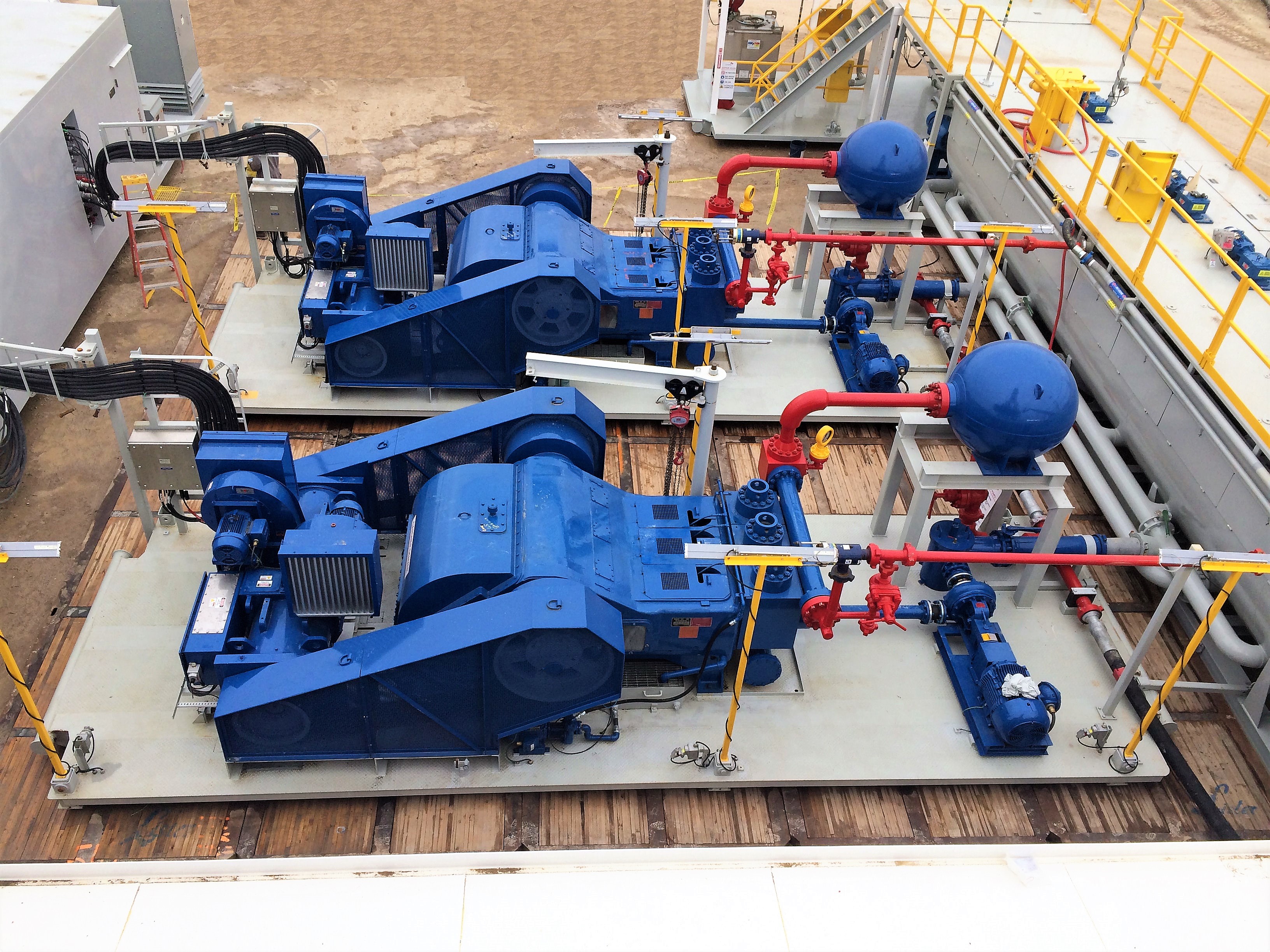
mud pump manifold manufacturer
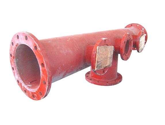
Discharge manifold is the main part of discharge end of mud pump. The material is 35CrMo. One end is equipped with an exhaust filter assembly that delivers the pressure generated by the mud pump directly to the well, and the other end is equipped with an air pack assembly and safety valve, a pressure gauge, through the drain elbow.

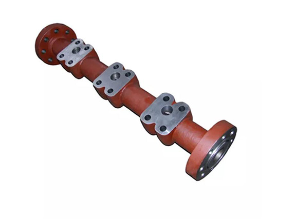
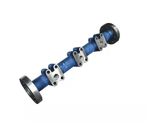
Suction manifold is the main part of suction end of mud pump. The material is 35CrMo. The suction manifolds are processed with high quality and seamless flanges. One end of it is equipped with a suction air bag, the remaining two flanges are inlet, and the user can choose one of its imports to inject mud or clean water according to the installation position of the pump group.
Cameron mud standpipe manifolds are designed and manufactured to customer requirements and are fully certified in accordance with the recognized oilfield equipment standards.
The mud standpipe manifold is installed downstream of the mud pumps with the purpose of diverting the flow of drilling fluids toward the drill line or drillstring. An adjustable choke can be installed to bleed pressure off the drillpipe, to reduce shock when breaking circulation in wells where loss of circulation is a problem, and to bleed off pressure between BOPs during stripping operations. Pressure ratings up to 7,500 psi are available.
The discharge pipe is the output end of the mud pump, one end of which is equipped with the discharge filter assembly to directly convey the pressure generated by the mud pump to the underground.The other end is equipped with the air package assembly and the relief valve and the pressure gauge through the discharge elbow.His material is characterized by corrosion resistance, wide range of temperature resistance and high strength. The configuration requirements of suction and discharge...

ACT’s high pressure cement manifolds are designed and manufactured to customer requirements. The ACT product line offers the widest range of hammer union ended equipment available from any one manufacturer. Purpose forged tees, crosses, “Y’s”, laterals, plug valves (two types), crossovers; the list is endless. This allows ACT to supply very competitively priced cement manifolds in a wide variety of sizes and configurations. Manifolds with pressure ratings up to 15,000 psi are available.
Provide a support point for the manifold module during the installation and recovery process; provide a support platform for the ROV during ROV operation.
The manifold and the well are completely independent in structure, and the oil well and the oil pipeline are connected to the manifold through the jumper. The management system consists of a manifold, a manifold support structure and an infrastructure. The manifold supports the junction between the structural manifold and the infrastructure.
The manifold consists of pipes, valves, control modules, flow meters, etc. On the chassis of the pipeline arrangement in the manifold, the oil and gas produced by the chassis well and the satellite well are collected by the manifold and piped to the platform. The injected water from the platform is distributed to each injection well through the manifold.
The manifold support structure consists of a frame made of pipe diameter and section steel. It functions to: provide guidance for drilling; provide a base for equipment installed under the underwater pipe; provide a carrier for underwater pipe sinking; protect the underwater pipe The exchange is not destroyed.

The stand pipe manifold is designed with provisions for stand pipe connection to the rig pumps (1 & 2), the cement pump and the kill line. This enables the conduction of drilling mud to the bit, and cement to the annulus, during drilling and cementation, respectively. In addition, a separate line connects this manifold to a manual adjustable choke. All lines can be isolated by gate valves. Below is a diagram showing the standpipe manifold:
The Drawwork console, which looks exactly like the one on a regular drilling rig contains five clutches and rheostat controls that control the drum, rotary table and the pumps (both mud and cement). In addition, the drawwork brake enhances a mechanism for controlling the weight on bit, penetration rate and the lifting of the drill string.

High quality, reliable manifold assemblies for standpipe, mud pump discharge, choke, cement and fracking applications. All customized to customer specifications and designed to meet API 6A and ASME B31.3 specs.
An assembly of valves that allows the driller to direct the drilling fluid coming back from the well bore. If the return fluid is under pressure, the choke manifold assembly will release that pressure at a controlled rate. The driller can then redirect the drilling fluid to a gas separator, a flare, or to holding tanks.
Allows the driller to assemble cement pumps and connect them to the steel casing in the drill hole so the cementing process can be completed. Drill hole casings must be cemented into the well bore to seal all formations across the hold bore section


 8613371530291