
mud pump manifold in stock
Explore a wide variety of mud pump suction manifold on Alibaba.com and enjoy exquisite deals. The machines help maintain drilling mud circulation throughout the project. There are many models and brands available, each with outstanding value. These mud pump suction manifold are efficient, durable, and completely waterproof. They are designed to lift water and mud with efficiency without using much energy or taking a lot of space.
The primary advantage of these mud pump suction manifold is that they can raise water from greater depths. With the fast-changing technology, purchase machines that come with the best technology for optimum results. They should be well adapted to the overall configuration of the installation to perform various operations. Hence, quality products are needed for more efficiency and enjoyment of the machines" full life expectancy.
Alibaba.com offers a wide selection of products with innovative features. The products are designed for a wide range of flow rates that differ by brand. They provide cost-effective options catering to different consumer needs. When choosing the right mud pump suction manifold for the drilling project, consider factors such as size, shape, and machine cost. More powerful tools are needed when dealing with large projects such as agriculture or irrigation.
Alibaba.com provides a wide range of mud pump suction manifold to suit different tastes and budgets. The site has a large assortment of products from major suppliers on the market. The products are made of durable materials to avoid corrosion and premature wear during operations. The range of products and brands on the site assures quality and good value for money.
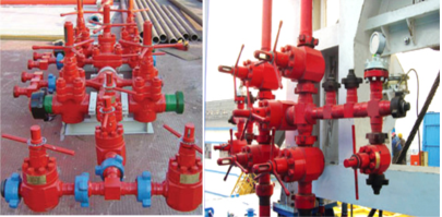
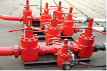
Cameron mud standpipe manifolds are designed and manufactured to customer requirements and are fully certified in accordance with the recognized oilfield equipment standards.
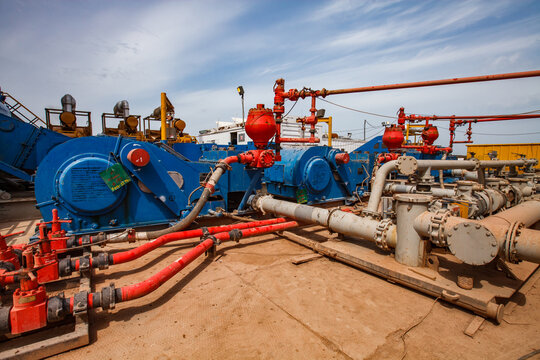
The mud standpipe manifold is installed downstream of the mud pumps with the purpose of diverting the flow of drilling fluids toward the drill line or drillstring. An adjustable choke can be installed to bleed pressure off the drillpipe, to reduce shock when breaking circulation in wells where loss of circulation is a problem, and to bleed off pressure between BOPs during stripping operations. Pressure ratings up to 7,500 psi are available.
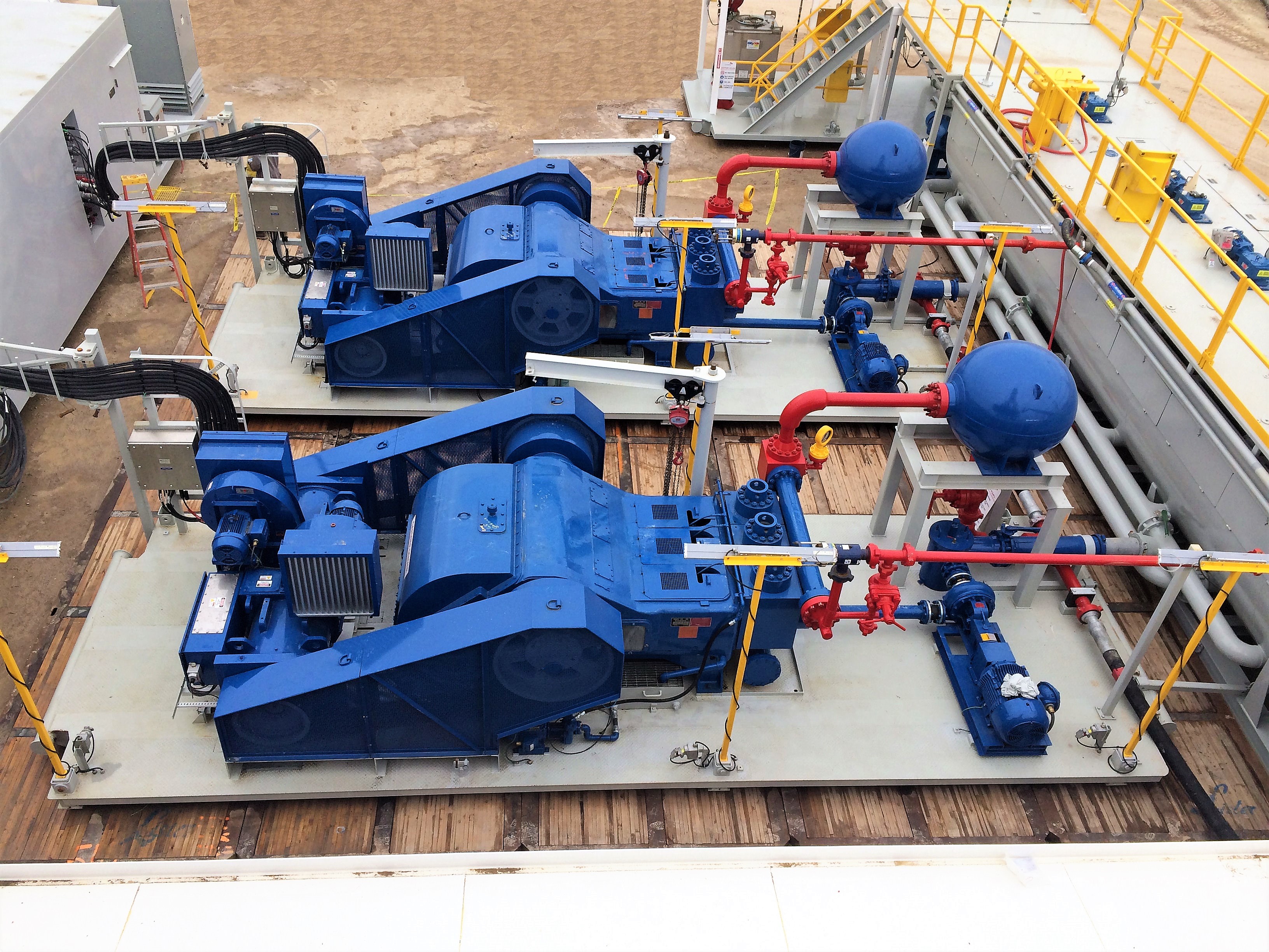
The NOV 12-P-160 Mud Pumps includes (3) Three New National 12-P-160 Triplex Mud Pumps 1600 HP, 7-1/4″ bore x 12″ stroke, single acting. 5000 PSI fluid ends. 1600 HP Bare Mud Pumps are currently configured for Offshore Service. The NOV 12-P-160 Mud Pumps are located in Houston and ready to be unitized for service.
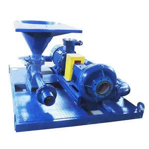
Forged Steel crankshaft, Individual forged steel two piece interchangeable standard modules, 6-1/2” mission fluid king liners, Standard polyurethane valves and seats, Two piece fast change piston rods, Supreme pistons, Metal to metal liner retention, Clamp type liner and piston rod connections, Fast change valve covers standard, Piston liner lubricant spray system, Liner spray pump, Power end lube system with filter. Mounted on Integral two runner skid, Suction Manifold with vertical suction stabilizer, Suction line pressure relief valve, set for 70 PSI
Includes: motor supports, motor frame, tensioning screws, 2 V-belt guards, 2 pump Sheaves, 2 motor sheaves, banded V-belts, Holes to be drilled to accept EDM D79 Or GE-752 Traction Motors
National Oilwell Varco (NOV) is an American multinational corporation based in Houston, Texas. It is a leading worldwide provider of equipment and components used in oil and gas drilling and production operations, oilfield services, and supply chain integration services to the upstream oil and gas industry. The company conducts operations in more than 600 locations across six continents, operating through three reporting segments: Rig Technologies, Wellbore Technologies, and Completion & Production Solutions. National Oilwell’s two main predecessors, Oilwell Supply and National Supply, were founded in 1862 and 1893, respectively. These two companies manufactured and distributed pumps and derricks.

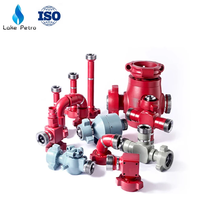
A Mud Pump may have many changeable parts, such as liner, piston, extension rod, pulsation dampener, valve, clamp, etc. Lake Petro could provide 100% interchangeable parts of many common brands of pump. We offer Liners with Ceramic (Zirconia and Aluminium oxide) and Steel (Metal and Bi-metal) materials. Piston assembly is the important spare parts and expendable parts of oil drilling mud pumps. Mud pump valve assy include valve body, valve seat, valve insert (valve rubber ). Pulsation Dampener is usually installed on the discharge line to reduce the fluctuation of pressure and displacement of the drilling mud pump. Fluid End Module is an important component of the hydraulic pump end of the mud pump.
We carry mud pumps, connecting rods, and more than 2,000 drawings and blueprints of oilfield equipment and supplies. We can fill your orders with one-of-a-kind designs for:
Our vast inventory of fluid-end and gear-end parts for duplex pumps includes more than 500 duplex liners, as well as cages and stuffing boxes. If you can’t find the model you are looking for below, let us find it for you.
We carry more than 1,500 duplex piston rods and 200 duplex pony rods in our inventory. Though we keep in stock connecting rods primarily for GA550 and GA750 models, other options are available, including custom connecting rods for most duplex and triplex mud pumps.
We now offer crossheads and guides for both EMSCO D-375 and DB-550 duplex pumps. We also have slides and shoes for certain models. If you don’t see a part you need, let us find it for you.
EC Tool offers Oteco gate valves, Demco gate valves, O’Drill pressure relief valves, manifold valves, butterfly valves, ball valves, and check valves. We also maintain a large inventory of spare parts for most of the valves we carry, including drive bushings and rotating heads from Kelly and other well-known brands.
Tecno Meccanica Emiliana besides realizing complete Fluid End, is also able to develop and deliver Discharge Manifold to the Continental Emsco FB1600 5000 PSI (OEM Style) Mud Pump.
The fluid end mainly consists of cylinder block, liner, piston, valve, suction manifold, discharge manifold, discharge pulsation dampener, relief valve and spraying device etc.
The arrangement of lines and valves used to direct and control fluid on a pumping unit. The manifold on the pump suction is generally known as the inlet or low-pressure manifold. The corresponding manifold located on the pump discharge is commonly known as the high-pressure or discharge manifold. In most cases, reference to the pump manifold relates to the high-pressure manifold.
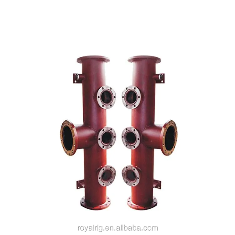
The discharge manifold is connected with 3 cylinder blocks simultaneously too. It has two ports at left and right side. The drilling fluid can be discharged from left side or right side.
The discharge filter shall be installed at the other side of discharge manifold. The discharging mud go to the drilling fluid line (manifold) after filtering.
Before the mud discharge manifold needs to be repaired, the bypass valve on pressure release line should be opened first, and let the pressure in discharge manifold to be released to zero.
Then install suction manifold and discharge manifold. After adjusting and aligning each part well, use a torque wrench to tighten the connection bolts between suction manifold, discharge manifold and cylinder blocks respectively to specified torque.
(1) Wash the contacting face between discharge manifold and cylinder blocks well, install the seal ring and put it onto cylinder blocks. The tightening torque of bolt M39×3 is 1954~2255N.m.
(2)As per discharge manifold requirement, install the accessory manifold (5-way or 4-way), discharge pulsation dampener, relief valve, bypass valve, and pressure release line etc. The tightening torques of bolts and nuts are required to meet clause 12.2.1.
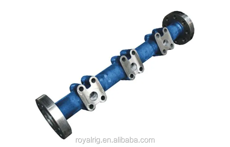
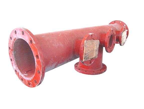
The suction manifold is connected to 3 cylinder blocks simultaneously. It has three ports at left , middle and right. The drilling fluid can be sucked in from left, right or middle port according to your desire.
(1) Install the suction manifold: clean the flange end face of suction manifold,install seal rings and connect it to three cylinder block. The tightening torque of bolt M39×3 is 321~370N.m
The fluid end mainly consists of cylinder block, liner, piston, valve, suction manifold, discharge manifold, discharge pulsation dampener, relief valve and spraying device etc.
(1) Wash the contacting face between discharge manifold and cylinder blocks well, install the seal ring and put it onto cylinder blocks. The tightening torque of bolt M39×3 is 1954~2255N.m.
(2)As per discharge manifold requirement, install the accessory manifold (5-way or 4-way), discharge pulsation dampener, relief valve, bypass valve, and pressure release line etc. The tightening torques of bolts and nuts are required to meet clause 12.2.1.
The suction manifold is connected to 3 cylinder blocks simultaneously. It has three ports at left , middle and right. The drilling fluid can be sucked in from left, right or middle port according to your desire.
(1) Install the suction manifold: clean the flange end face of suction manifold,install seal rings and connect it to three cylinder block. The tightening torque of bolt M39×3 is 321~370N.m
The discharge manifold is connected with 3 cylinder blocks simultaneously too. It has two ports at left and right side. The drilling fluid can be discharged from left side or right side.
The discharge filter shall be installed at the other side of discharge manifold. The discharging mud go to the drilling fluid line (manifold) after filtering.
Before the mud discharge manifold needs to be repaired, the bypass valve on pressure release line should be opened first, and let the pressure in discharge manifold to be released to zero.
Then install suction manifold and discharge manifold. After adjusting and aligning each part well, use a torque wrench to tighten the connection bolts between suction manifold, discharge manifold and cylinder blocks respectively to specified torque.

The majority of problems occurring with reciprocating pumps originate on the suction side of the pump. The term “suction” can be misleading due to the fact that single acting pumps do not lift liquid or suck. A better term to use is “the line leading to the inlet manifold on the pump.” Single acting pumps rely upon atmospheric pressure to force the liquid into a low pressure area created by the completed discharge stroke of the piston or a centrifugal pump with sufficient head and flow to deliver liquid to the inlet manifold as needed.
The inlet side of the pump is critical to correct operation. Collapsible hose should never be used on the inlet side and length is always a factor because friction loss will enter the picture. The inlet line should have a large inside diameter, straight and short as possible. This type system yields a huge benefit to the cost of overall maintenance of the pump. The inlet to the pump should be as close to the supply source as possible and sized according to the discharge flow of the pump. Never decrease the inlet manifold diameter of the liquid end in order to use a smaller inlet hose. Always increase the inlet hose by 1 or 2 in. to ensure good inlet conditions for the pump. The inlet velocity should never be less than 1 ft per second or greater than 3 ft per second.
When problems start to occur on the inlet side, those problems can be both visual and audible. The inlet line will start to pulsate. This occurs because of the liquid accelerating and decelerating rapidly. On each rotation of a triplex crankshaft, one inlet valve will be closed and another will be partially open. The third will be fully open on the discharge stroke. This movement of the valves causes the liquid within the supply line to try and stop, start toward the pump and reverse toward the supply all at the same time. Therefore, poorly designed supply lines will show this movement in pulsating form.
This pulsation can also be audible within the pump. You will hear hammering and if severe enough, the discharge line will also began to pulse. If this much cavitation is occurring within the pump, severe damage can and will occur within the power end as well as the liquid end if conditions are not changed. The hammering sound is the audible form of pump cavitation.
Cavitation is caused by insufficient flow or head from the supply tank to the inlet of the pump and the smooth transition from the manifold through the throat of the inlet valve. If the liquid is too viscous or the supply of the liquid is insufficient to meet the required speed (gpm) of the pump, gasses will start to break out of the liquid and form bubbles in the slurry as it passes through the throat of the inlet valve. When the pump is on the discharge stroke and pressure starts to build rapidly from atmosphere to discharge pressure, the bubbles start to implode and cause damage to liquid end components as well as the liquid end itself.
A suction valve or inlet valve is nothing more than an orifice within the system. The suction manifold of the pump should be filled with liquid and moving at a consistent flow rate. As an inlet valve begins to open and liquid flows through, the liquid should be in contact with the face of the piston. This column of liquid should move at the same rate as the piston. If the inlet is inadequate or pump speed too great, gas will break from the liquid in the low pressure zone created by the inlet seat and bubbles will from in the pumping chamber or atmosphere will enter through the liner and piston. Either way, the pumping chamber will not be filled with liquid.
When the discharge stroke begins, the piston is at rest. Half way through the discharge stroke, the piston is traveling at maximum velocity. Ideally, the pumping chamber should be filled with liquid and in contact with the face of the piston. The inlet valve within that chamber should have just closed as the piston starts the discharge stroke. If bubbles have formed, the chamber is only partially filled with liquid. As pressure starts to build within the chamber, the bubbles implode and the piston encounters a partially filled chamber traveling at maximum velocity slamming open the discharge valve and causing a shock wave to be sent throughout the entire system.
If a pump has a satisfactory inlet system, the end user will see the results of that in his hip pocket. If not, he will help support the entire industry with more equipment sales.
Stock Equipment : New, unused pump manifold skid as per P&ID Quantity : 1 off (4 skids) Service : Crude Export Pumps Manifold Skid complemented with pumps suction and discharge instrumentation and PSVs. Size : Pump Manifold 20” suction and 12” discharge sized for 100,000 BPL. All other pipework sized for 38,000 BPD Nozzle sizes : 20” ANSI 150# RF inlet and 12” ANSI 600# RF outlet Instrument Hazardous Area : Class I, Div. 2
FET manufactures a full range of valves and seats for every drilling and well-servicing application as part of our full line of Osprey® mud pump system solutions. All of our valves and seats can be used in water, water base, oil base and synthetic base mud applications. FET offers additional valves and seats not listed below, including drilling valves, frac valves and well service valves. FET’s QC standards for the dimensional and material specs are extremely rigid in comparison to other manufacturers. Contact your FET representative to learn more.

A mud pump (sometimes referred to as a mud drilling pump or drilling mud pump), is a reciprocating piston/plunger pump designed to circulate drilling fluid under high pressure (up to 7,500 psi or 52,000 kPa) down the drill string and back up the annulus. A mud pump is an important part of the equipment used for oil well drilling and manufactured according to API specification 7K.
The advantages of the drilling mud pump include the ability to move high-solids-content fluids laden with abrasives, the ability to pump large particles, ease of operation and maintenance, reliability, and the ability to operate over a wide range of pressures and flow rates by changing the diameter of pump liners and pistons.
The fluid end includes cylinders (module), valve assembly, cylinder liners, piston assembly, suction manifold, discharge manifold, piston rod, pulsation dampener assembly, etc.
As an important equipment for oilfield drilling operation, a drilling mud pump delivers circulating high-pressure drilling fluid or drilling mud to the bottom of the oil well, flushes the bottom of the well, breaks the rock, cools, lubricates and clean the drill bit, and carries the cuttings back to the ground.
The drilling mud is also used to suspend and carry out drill cuttings from the drill bits as it is brought in and out of the hole. This ensures that the drill bit does not clog and overheat, and makes the entire drilling operation smooth and safe.
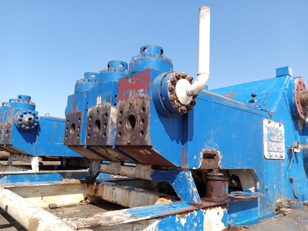
Rotational power is supplied to the mud pump through an external power source like a diesel engine or electric motor. The power end of the mud pump converts the rotational energy through a crankshaft to a reciprocating motion of pistons.
The pistons move back and forth in mud pump liners, exerting a force on the cylinder chamber. During the retraction of the piston, valves open to allow the fluid to be drawn into the cylinder. Once the piston has fully retracted, it is pushed back into the cylinder.
For Fluid End: piston rod clamp, piston rod, piston assembly, cylinder cover, liner, liner flange, wear plate, cylinder, valve assembly, valve cover, valve guide, flashboard assy., cylinder cover flange, cylinder head, gaskets, studs, nuts, seal rings, pulsation dampener, bladder, discharge manifold, suction manifold, etc.
Increasing drilling capacity includes upgrading the horsepower that drives your mud pumps. Whether your rig is using standard 5,000 psi systems or lower ratings, HENDERSON can upgrade it to 7,500 psi.
A failing mud pump at your site could be caused by a number of reasons. Instead of risking downtime, call HENDERSON to complete a full Tear Down & Inspection service to get you back up and running as soon as possible.
HENDERSON offers a TDI service that consists of complete disassembly of your mud pump. With everything taken apart, our team will inspect the suction manifold, check piston rods for straightness, look for visible washouts and pitting, and even inspect all nuts, bolts, and their threads!


 8613371530291