
mud pump pulsation dampener pressure free sample
A properly serviced pulsation dampener is critical for your mud pumps’ efficiency, safety, and performance. Unfortunately, there aren’t many resources available to educate personnel on executing safe and effective servicing procedures. Please review the following steps with your personnel for safe pulsation dampener maintenance.
Should you or your personnel have any questions regarding pulsation dampener maintenance, please don’t hesitate to ask. Sigma is more than happy to help you to ensure safe and proper care is being completed on your pulsation dampening equipment.

At Sigma Drilling Technologies, we utilize out-of-the-box thinking and cutting edge innovation. From our revolutionary pulsation control systems, to our one of a kind performance boosting solutions, Sigma delivers unsurpassed technology. Helping businesses succeed by getting the most out their equipment investment is our goal. Let us partner with your team to help maximize your production output, enhance equipment investment, and place you at the forefront of industry advancements.

This device is designed to reduce pulsations (pressure fluctuations) that occur with systems that have a positive displacement pump. Rubber bladder is pre-charged with nitrogen up to 50-60% of the system pressure. As water passes by the pulsation dampener, it absorbs the pulsations that come from the movement of water in the system. It is designed to protect pump equipment and piping in the system and can reduce pulsations down to 4%.

This equipment plays an important role as an accessory to Yamada air-operated double diaphragm pumps. The pulsation dampener serves to reduce pulsation produced in operation and to assure stable discharge flow and pressure.
When pulsations occur with pump operation, it will result in the pressure in Chamber Bbeing greater than that in Chamber A. The diaphragm will act as an air cushion and automatically adjust to this pressure change and absorb the pulsations.
This operation will shift the center rod position upwards and allow more air in Chamber Athrough the air inlet, returning the diaphragm to a neutral position. If liquid pressure decreases, air pressure in Chamber Acauses the diaphragm to move downward, shifting shaft location and changing valve position, releasing excess air pressure in Chamber Awhich returns diaphragm to a neutral position. This action causes a reduction in surges and pulsation caused by a air operated double diaphragm pumps

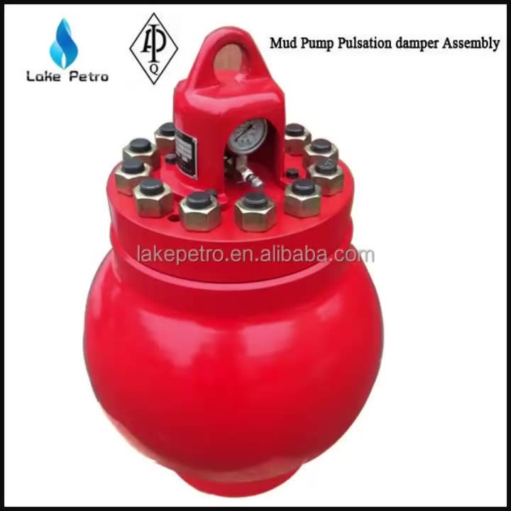
Mud Pump Pulsation Dampener is usually installed on the discharge line to reduce the fluctuation of pressure and displacement of the drilling mud pump.
Mud Pump Pulsation Dampener is a pneumatic device built into the outflow line of each UUD pump to dampen the pressure fluctuations resulting from the action of the pump. Although presented as a surge tank, this device is really a device that can be tuned to greatly diminish the output pulsations transmitted downstream from the mud pump. Unfortunately, the effectiveness of the pulsation dampener is a function of both output pump pressure and frequency of the pump pulsations.

My first days as an MWD field tech I heard horror stories surrounding what is commonly referred to as “pump noise”. I quickly identified the importance of learning to properly identify this “noise”. From the way it was explained to me, this skill might prevent the company you work from losing a job with an exploration company, satisfy your supervisor or even allow you to become regarded as hero within your organization if you’ve proven yourself handy at this skill.
“Pump noise” is a reference to an instability in surface pressure created by the mud pumps on a modern drilling rig, often conflated with any pressure fluctuation at a similar frequency to pulses generated by a mud pulser, but caused by a source external to the mud pulser. This change in pressure is what stands in the way of the decoder properly understanding what the MWD tool is trying to communicate. For the better part of the first year of learning my role I wrongly assumed that all “noise” would be something audible to the human ear, but this is rarely the case.
In an ideal drilling environment surface pressure will remain steady and all pressure increases, and decreases will be gradual. This way, when the pulser valve closes(pulses), it’s easily detectable on surface by computers. Unfortunately drilling environments are rarely perfect and there are many things that can emulate a pulse thus causing poor or inaccurate data delivery to surface. The unfortunate circumstance of this means drilling operations must come to halt until data can once again be decoded on surface. This pause in the drilling process is commonly referred to at NPT or non-productive time. For those of you unfamiliar these concepts, I’ll explain some of the basics.
A mud pulser is a valve that briefly inhibits flow of drilling fluid traveling through the drill string, creating a sharp rise and fall of pressure seen on surface, also known as a “pulse”.
Depending on if the drilling fluid is being circulated in closed or open loop, it will be drawn from a tank or a plastic lined reservoir by a series(or one) mud pumps and channeled into the stand pipe, which runs up the derrick to the Kelly-hose, through the saver sub and down the drill-pipe(drill-string). Through the filter screen past an agitator or exciter, around the MWD tool, through a mud motor and out of the nozzles in the bit. At this point the fluid begins it’s journey back to the drilling rig through the annulus, past the BOP then out of the flow line and either over the shale shakers and/or back in the fluid reservoir.
Developing a firm grasp on these fundamentals were instrumental in my success as a field technician and an effective troubleshooter. As you can tell, there are a lot of components involved in this conduit which a mud pulser telemeters through. The way in which many of these components interact with the drilling fluid can suddenly change in ways that slightly create sharp changes in pressure, often referred to as “noise”. This “noise” creates difficulty for the decoder by suddenly reducing or increasing pressure in a manner that the decoder interprets a pulse. To isolate these issues, you must first acknowledge potential of their existence. I will give few examples of some of these instances below:
Suction screens on intake hoses will occasionally be too large, fail or become unfastened thus allowing large debris in the mud system. Depending on the size of debris and a little bit of luck it can end up in an area that will inhibit flow, circumstantially resulting in a sudden fluctuation of pressure.
Any solid form of drilling fluid additive, if improperly or inconsistently mixed, can restrict the flow path of the fluid resulting in pressure increase. Most notably this can happen at the pulser valve itself, but it is not the only possible outcome. Several other parts of this system can be affected as well. LCM or loss of circulation material is by far the most common additive, but the least overlooked. It’s important for an MWD technician to be aware of what’s being added into the drilling fluid regardless if LCM isn’t present. Through the years I have seen serval other improperly mixed additives cause a litany of pressure related issues.
This specifically is a term used to refer to the mud motor stator rubber deterioration, tearing into small pieces and passing through the nozzles of the bit. Brief spikes in pressure as chunks of rubber pass through one or more nozzles of the bit can often be wrongly interpreted as pulses.
Sometimes when mud is displaced or a pump suction isn’t completely submerged, tiny air bubbles are introduced into the drilling fluid. Being that air compresses and fluid does not, pulses can be significantly diminished and sometimes non-existent.
Formation cuttings staying downhole can cause what is known as a pack-off of the anulus, which typically cause slower trends in pressure. A pack-off is less likely to cause significant decoding issues, but can.
Failed surface equipment such as transducers and transducer cables can occasionally allow current external to the circuit into the signal wire, resulting in what appears to be a pressure increase on the decoder. When experiencing poor decoding these are some of the first pieces of equipment to be replaced.
As many of you know the downhole mud motor is what enables most drilling rigs to steer a well to a targeted location. The motor generates bit RPM by converting fluid velocity to rotor/bit RPM, otherwise known as hydraulic horsepower. Anything downhole that interacts with the bit will inevitably affect surface pressure. One of the most common is bit weight. As bit weight is increased, so does surface pressure. It’s important to note that consistent weight tends to be helpful to the decoder by increasing the amplitude of pulses, but inconsistent bit weight, depending on frequency of change, can negatively affect decoding. Bit bounce, bit bite and inconsistent weight transfer can all cause pressure oscillation resulting in poor decoding. Improper bit speed or bit type relative to a given formation are other examples of possible culprits as well.
Over time mud pump components wear to the point failure. Pump pistons(swabs), liners, valves and valve seats are all necessary components for generating stable pressure. These are the moving parts on the fluid side of the pump and the most frequent point of failure. Another possible culprit but less common is an inadequately charged pulsation dampener. Deteriorating rubber hoses anywhere in the fluid path, from the mud pump to the saver sub, such as a kelly-hose, can cause an occasional pressure oscillation.
If I could change one thing about today’s directional drilling industry, it would be eliminating the term “pump noise”. The misleading term alone has caused confusion for countless people working on a drilling rig. On the other hand, I’m happy to have learned these lessons the hard way because they seem engrained into my memory. As technology improves, so does the opportunities for MWD technology companies to provide useful solutions. Solutions to aid MWD service providers to properly isolate or overcome the challenges that lead to decoding issues. As an industry we have come a lot further from when I had started, but there is much left to be desired. I’m happy I can use my experiences by contributing to an organization capable of acknowledging and overcoming these obstacles through the development of new technology.
The DA Series pulsation dampeners utilize a manual charge process, offer a flexible PTFE diaphragm that separates the liquid and compressed air chambers and can be installed in any position. Adjusting the inlet air pressure to the unit until the pump runs smoothly allows the dampener diaphragm to stroke at the same rate as the in-line AODD pump, effectively “dampening” the flow and discharge fluctuations.
DA pulsation dampeners are suitable for SANDPIPER ½" (S05) and ¾" (S07, S10) pump models and are available in polypropylene, PVDF, aluminum or stainless steel wetted housings.
The SANDPIPER TA Series pulsation dampener will self-adjust to application conditions by inletting or exhausting compressed air from the unit’s air chamber following application of full plant air (not to exceed 125 psi) to the tranquilizer. The pulsation dampener will automatically adjust to its optimum performance condition in order to maximize surge suppression, reducing both piping vibration and noise.
TA pulsation dampeners are suitable for SANDPIPER 1", 1½", 2" and 3" metallic pump models and are available in aluminum, cast iron and stainless steel wetted housings with various diaphragm (elastomer) options.

This present invention is directed to drilling wellbores in the earth, to systems for pumping drilling fluid (“mud”) for such operations, to mud pumping system modules with surge suppressing dampeners, and to methods of their use. DESCRIPTION OF THE RELATED
Known references disclose a wide variety of drilling systems, apparatuses, and methods including, but not limited to, the disclosures in U.S. Pat. Nos. 6,944,547; 6,918,453; 6,802,378; 6,050,348; 5,465,799; 4,995,465; 4,854,397; and 3,658,138, all incorporated fully herein for all purposes. Prior references disclose a wide variety of drilling fluid pumps (“mud pumps”) used in drilling operations and pump systems, for example, and not by way of limitation, those pumps and systems disclosed in U.S. Pat. Nos. 6,257,354; 4,295,366; 4,527,959; 5,616,009; 4,242,057; 4,676,724; 5,823,093; 5,960,700; 5,059,101; 5,253,987; in U.S. application Ser. No. 10/833,921 filed Apr. 28, 2004(all said U.S. references incorporated fully herein for all purposes). Known references disclose a variety of dampeners, accumulators, and surge suppressors; including, but not limited to, those disclosed in U.S. Pat. Nos. 4,299,253; 4,195,668; 2,757,689; 2,804,884; 3,674,053; 3,169,551; 3,674,053; 3,162,213; 2,380,866; 2,378,467; 2,397,248; 2,397,796; and 2,773,455—all incorporated fully herein for all purposes.
A drill bit carried at an end of a drillstring is rotated to form wellbores in the earth. Certain drillstrings include tubulars which may be drill pipe made of jointed sections or a continuous coiled tubing and a drilling assembly that has a drill bit at its bottom end. The drilling assembly is attached to the bottom end of the tubing or drillstring. In certain systems, to drill a wellbore, the drill bit is rotated (e.g., by a top drive, a power swivel, a rotary table system, or by a downhole mud motor carried by the drilling assembly). Drilling fluid, also referred to as “mud,” is pumped through the wellbore under pressure from a pit or container at the surface by a pumping system at the surface.
In certain known mud pump systems, suction and discharge modules have valves therein that selectively control fluid flow through the module in an intake (suction) mode in which piston apparatus creates a vacuum drawing drilling fluid into the module and in an output mode (Discharge) in which the piston apparatus creates pressure forcing drilling fluid out of the module. In the suction mode, a suction valve opens allowing drilling fluid into the module while a discharge valve remains closed. In the discharge mode, the pressure of the drilling fluid closes the suction valve and opens the discharge valve.
Both valves, the suction valve and the discharge valve, are subjected to the erosive and damaging effects of the flow of drilling fluid. The drilling fluid contains drilled cuttings and debris which can erode valve parts (e.g. seats, stems, valve members, seals, guide bushings, insert, liners, wear plates etc.). Also, mud pumps which can pump relatively hot drilling fluid at, e.g., 500 to 2000 gallons per minute, force the erosive drilling fluid against the valve parts at high velocities which add to the fluid"s damaging effects.
In many valves used in mud pump systems, a guide in the valve which is disposed across a flow path or guide fingers extending from a valve member into a valve seat guide a valve member so that valve member seats correctly and effectively against the valve seat. In many valves, the valve seat surface against which the valve member (or poppet) seats is, ideally, flat; and the surface of the valve member which sealingly abuts the flat seat surface of the valve seat is, correspondingly, and ideally, flat. A guide or guide fingers facilitates correct seating of the valve member"s flat seating surface against the valve seat"s flat seat surface. If either surface is not flat, or if one surface does not contact the other in a substantially parallel (flat surface to flat surface) manner, ineffective or inefficient valve operation may result.
In many known mud pump valves, the valves are opened and closed by mechanically creating a vacuum or fluid pressure increase in the valve that overcomes a spring to allow a valve member to move. The movement of the valve member is not controlled, i.e., it is subject to a surge of fluid under pressure. As fluid pressure builds up to move a valve member, a corresponding amount of fluid builds up adjacent the valve. when the pressure is high enough, a relatively large charge of fluid goes through the valve at high velocity. This surge of fluid can have deleterious effects on valve parts. BRIEF SUMMARY OF THE INVENTION
The present invention, in at least certain embodiments, discloses systems for pumping a drilling fluid mixture, the drilling fluid mixture containing drilling fluid and solids, the systems having: a pump apparatus; the pumping apparatus having a body with a pumping chamber, an inlet and an outlet; a suction valve in the body for selectively controlling flow of the drilling fluid mixture in through the inlet; a discharge valve in the body for selectively controlling flow of the drilling fluid mixture out through the outlet; and a dampener system according to the present invention in fluid communication with the pumping chamber.
Such a pump system according to the present invention, in one aspect, includes: a base; a housing connected to the base, the housing having an interior; a liner within the housing, the liner expandable in response to fluid pressure; a piston/cylinder apparatus in fluid communication with the housing; the piston/cylinder apparatus having a movable piston movable in response to fluid flowing from the housing to the piston/cylinder apparatus; a torsion apparatus movably connected to the base, the piston movable to contact and to move the torsion apparatus in response to fluid flowing from the housing to the piston/cylinder apparatus; and the torsion apparatus movable by the piston from a first static position to a second position to dampen pulsations of fluid into the pumping chamber.
In one aspect, a pumping system according to the present invention has a dampener system according to the present invention which includes: a housing, the housing having an interior; a deformable bladder within the housing, the deformable bladder in fluid communication with the pumping chamber; and the deformable bladder deformable in response to pressure variation in the pumping chamber.
The present invention discloses, in certain aspects, dampeners for drilling fluid pumping systems which suppress and/or eliminate the damaging effects of undesirable pulsations or surges of drilling fluid passing through the systems. In certain aspects, the dampener has a liner with liquid therein which expands and contracts in response to the pressure of drilling fluid passing through a pumping system.
The present invention discloses, in certain aspects, dampeners for drilling fluid pumping systems in which the dampener has a liner with liquid therein which expands and contracts in response to the pressure of drilling fluid passing through a pumping system. In certain aspects, a dampener according to the present invention has a torsion apparatus that absorbs and then releases energy to facilitate the dampening of drilling fluid surges. In other aspects, a dampener system according to the present invention has an inflatable bladder surrounded by an expandable spring member, both the bladder and the spring member responsive to drilling fluid surges to suppress deleterious effects of such surges.
The present invention discloses, in certain aspects, modules for a drilling fluid pumping system which include a dampener for suppressing and/or eliminating the damaging effects of undesirable pulsations or surges of drilling fluid passing through the modules. In certain aspects, the dampener is within a block of the module that also contains suction and discharge valve assemblies within a module block.
The present invention discloses, in certain aspects, a drilling fluid pumping system, also known as a mud pump system, for pumping drilling fluid or mud used in wellbore operations which has pumping modules with valves that have non-flat seating surfaces. In certain aspects, such valves have a valve member or poppet that is movable with multiple degrees of freedom in any of which effective seating of the valve member against a valve seat is achieved. In particular aspects of such a valve, dual sealing is achieved by sealing of a valve member against both a valve seat and against a seal disposed in a valve seat.
In certain particular aspects of a mud pump system according to the present invention, a mud pump valve has a tapered spring biased against a valve member which enhances the free seating movement of a valve member.
The present invention discloses, in certain aspects, valves for a system for pumping a drilling fluid mixture, the drilling fluid mixture containing drilling fluid and solids, the valves having: a seat with a valve seat surface; a valve member with a member surface, part of the valve member movable to seat the member surface against the valve seat surface to prevent the flow of the drilling fluid mixture past the valve seat; a cartridge stem positioned with respect to the valve member, and a valve actuator within the cartridge stem for selectively moving the valve member. In certain aspects, the present invention discloses a system for pumping a drilling fluid mixture, the drilling fluid mixture containing drilling fluid and solids, the system having: a pump apparatus; the pumping apparatus having a body with an inlet and an outlet; a suction valve in the body for selectively controlling flow of the drilling fluid mixture in through the inlet; a discharge valve in the body for selectively controlling flow of the drilling fluid mixture out through the outlet; and a dampener within the body for inhibiting pulsations of fluid pumped from the pump apparatus In certain valves according to the present invention a valve actuator is used which is pneumatically powered without certain mechanically moving parts used in prior valves.
Accordingly, the present invention includes features and advantages which are believed to enable it to advance pumping system technology. Characteristics and advantages of the present invention described above and additional features and benefits will be readily apparent to those skilled in the art upon consideration of the following description of preferred embodiments and referring to the accompanying drawings.
What follows are some of, but not all, the objects of this invention. In addition to the specific objects stated below for at least certain embodiments of the invention, other objects and purposes will be readily apparent to one of skill in this art who has the benefit of this invention"s teachings and disclosures. It is, therefore, an object of at least certain preferred embodiments of the present invention to provide new, useful, unique, efficient, nonobvious dampener systems for drilling fluid pumping systems and methods of their use;
FIG. 2F is a perspective view, partially cutaway, of a pump module according to the present invention with valve assemblies according to the present invention.
The system 500 shown in FIG. 1 includes a derrick 502 from which extends a drillstring 504 into the earth 506. The drillstring 504, as is well known, can include drill pipes and drill collars. A drill bit 512 is at the end of the drillstring. A rotary system 514, top drive system 526, and/or a downhole motor 532 (“fluid motor”, “mud motor”) may be used to rotate the drillstring 504 and the drill bit 512. A typical drawworks 516 has a cable or rope apparatus 518 for supporting items in the derrick 502. A mud pump system 522 according to the present invention with one, two, three-to-ten, or more mud pumps 521 according to the present invention each with pumping modules with one or two valves according to the present invention supplies drilling fluid 524 to the drillstring 504. Drilling forms a wellbore 530 extending down into the earth 506. Each mud pump 521 has at least one valve 501 according to the present invention or (as shown in FIG. 1A schematically) multiple pumping modules 503 each with a suction valve 505 according to the present invention and a discharge valve 506 according to the present invention. Each mud pump 521 has a main crank shaft 521 c.
During drilling, the drilling fluid 524 is pumped by pump(s) 521 of the mud pump system 522 into the drillstring 504 (thereby operating a downhole motor 532 if such an optional motor is used). Drilling fluid 524 flows to the drill bit 512, and then flows into the wellbore 530 through passages in the drill bit 512. Circulation of the drilling fluid 524 transports earth and/or rock cuttings, debris, etc. from the bottom of the wellbore 530 to the surface through an annulus 527 between a well wall of the wellbore 530 and the drillstring 504. Cuttings and debris are removed from the drilling fluid 524 with equipment and apparatuses not shown, and it is re-circulated from a mud pit or container 528 by the pump(s) of the mud pump system 522 back to the drillstring 506. Also, some desirable solids may be added to the drilling fluid.
A system 10 according to the present invention as shown in FIGS. 2A and 2B has a main housing 12 mounted on a base 8 with an optional crane system 20 for lifting and moving system parts. A pedestal 21 of the crane system 20 is rotatably mounted on a bearing assembly 22 on the housing 12. A lift apparatus 23 is movably mounted on a beam 24 and a support 25 extends down from the lift apparatus 23. A chain hoist lift may be used with the structure shown which is attached to the support 25. Motors 14 each drive pinions 16 which in turn drive a drive gear 18 (see FIG. 3C) to move pistons 19 for six removable pump modules 650 (as described below; may be any module disclosed herein and/or may have any valve assembly or valve assemblies disclosed herein). A pressure relief apparatus (e.g. one or more relief valves) is provided for the modules 650 and, as shown, in one aspect, for each of the six modules 650 there is a pressure relief valve 13. Optional rails 15 project up from the housing 12.
An oil pump 2 pumps lubricating oil to various parts of the system. A water pump 4 pumps water to a filtration system (not shown) and a cooler (not shown). The pumps are mounted on pump mounts 8 bconnected to the base 8. Doors 3 and 5 (one each for each pump system 30) provide access to various internal parts of the system 10. Drilling fluid enters the system 10 through an inlet 7 and is pumped out via the modules 650 to a main outlet 9.
The modules 650 have a body 602 with a first bore 602 aand a second bore 602 b. A discharge valve assembly according to the present invention is in the first bore and a suction valve assembly according to the present invention is in the second bore. With a piston fluid is pumped into a chamber 652 of the module 650 via an inlet port 604 and is discharged from the module 650 into a discharge conduit 634 via an outlet port 606.
FIG. 2F shows the relative positions of two valve assemblies 100 a, 100 b(like the valve assembly 100) according to the present invention as they are present in a block of a mud pump module. The valve assemblies 100 a, 100 b(which may be any valve assemblies disclosed herein) are in bores 642, 643, respectively, in a block 644. The block 644 can be used in a system like that of FIG. 2A.
FIGS. 2G-2I show two valve assemblies 100 x, 100 y(like the valve assembly 100 a, FIG. 9A; may be any valve assembly according to the present invention) as they are disposed in a block B (shown in dotted line; may be any suitable block or body; including, but not limited to, the body 602 or block 644 referred to above) of a mud pump system. Fluid is sucked in by action of the suction valve assemblies 100 xthrough a suction inlet 400 and discharged by action of the discharge valve assembly 100 ythrough a discharge outlet 402. The fluid is received in a pumping chamber 404.
Fluid pumped from the chamber 404 can impact parts of the discharge valve 100 x. Optionally, an accumulator/dampener 410, positioned within the block B, is in fluid communication with the pumping chamber 404. The accumulator/dampener 410 reduces undesirable pulsations of fluid under pressure from the pumping chamber 404. Any suitable known accumulator/dampener may be used.
FIGS. 3A and 3B show a valve assembly 100 according to the present invention which can serve as a suction valve or a discharge valve for a mud pump system (e.g., but not limited to, the suction valve assembly 680 and the discharge valve assembly 630 described above; or the suction valve 100 xand the discharge valve 100 ydescribed above). FIG. 4 shows top portions of the valve assembly 100.
In one aspect, as shown in FIG. 5, the valve actuator 130 is a controlled, pneumatically powered actuator known as a FESTO (TRADEMARK) “muscle” actuator. The actuator 130 has an expandable hose 132 mounted between two bases 134, 135. Air under pressure is introducible into the interior of the hose 132 through a channel 137 in a pneumatic coupling 139. The upper base 134 is connected to an adapter support 127 to which the adapter 106 is secured.
As shown in FIG. 5, air under pressure has not yet been applied within the hose 132. Once air is applied the hose moves outwardly, effectively moving the top base 134 toward the lower base 135 and thereby pulling the adapter 106 to pull the cable 128 and move the poppet 114 out of sealing contact with the valve seat 160 against the force of the spring 120.
FIG. 6 shows one embodiment, a spring 120 a, of a spring 120. As compared to prior known spring designs, the spring 120 ahas a spring body with a smaller spring diameter, a, and with a higher spring force; but the wire diameter is relatively large, e.g. 0.22 inches, which results in the higher spring force. Use of an actuator like the actuator 130, FIG. 5, makes it possible to use a spring with the increased spring force (with the increased wire diameter). The overall diameter, b, of the spring 120 ais relatively smaller than prior springs because the spring 120 adoes not have to accommodate the relatively large necks of certain prior valve members. Certain prior mud pump valve springs reached a known resonant frequency (e.g. about 40 Hz to 43 Hz) creating poppet oscillations that resulted in an improperly seated poppet and in fluid pulsations transmitted downstream of a valve assembly. Due to its size and weight, the spring 120 ahas a higher natural frequency than those prior springs which resonate around 40 Hz and, thus, more force is required to resonate the spring 120 a. In certain aspects the spring 120 (or 120 a; or the spring 120 b, FIG. 7A) is sized and configured so its natural resonant frequency is about 25% higher than that of certain known springs (e.g., in one aspect 50 Hz vs 43 Hz). This reduces the chance of flow-induced resonance in the valve assembly with such a spring; provides better, more stable control of the valve assembly"s poppet; and provides more positive seating of the poppet against the valve seat.
FIGS. 8A and 8B illustrate steps in the operation of a valve assembly 100 (which has a spring 120 b, although any suitable spring may be used). As shown in FIG. 8A, air under pressure has not yet been applied within the hose 132 and the and the spring 120 burges the poppet 114 into sealing contact with the seal 169 and with the valve seat 160. The valve assembly 100 is closed to fluid flow therethrough. Fluid pressure also forces the poppet against the valve seat. On the discharge side of the valve seat at the beginning of the pumping/compression part of a cycle, the spring 120 band the fluid within a discharge manifold pushes the poppet 114 against the seat. This continues until the pressure within the discharge manifold drops below the pressure within the pumping cylinder and/or until the actuator 130 is commanded to open. On the suction side, the fluid within the pumping cylinder pushes the poppet 114 against the seat 160 again during the compression part and until the actuator 130 is commended to open the valve. When the “muscle” of the actuator 130 is not expanded, there is residual air trapped between the commanding valve and the actuator 130. The pressure of this trapped air is close to the pressure that existed in this line at the moment of exhausting the air and closing off the valve"s exhaust port. When the actuator is flexed, there is air at a pressure that is sufficient to open the valve, e.g. 110 psi. The actuator and air lines are filled in order to decrease the actuator"s response time—the time to respond to a commanding pressure. If the actuator is completely empty or, with, e.g. air at atmospheric pressure, it will take slightly longer for the actuator to respond, because when such a high pressure is applied the cavity would have to be filled with air first, then compress the air just introduced to a high enough pressure to barely stretch the hose 132 and only after that will the hose 132 change its length or respond to a commanding pressure.
As shown in FIG. 8B, air under pressure from an air supply 200 (with a proportional control valve 200 p) has been applied within the hose 132 causing it to expand and pulling the cable 128 away from the valve seat 160. In so doing, the poppet 114 is moved out of sealing contact with the seat 160 and the seal 169 of the valve seat 160 and the valve assembly is opened to fluid flow permitting fluid to flow into and out from a mud pump module housing the valve assembly.
It is advantageous that the poppet is part of the valve cartridge. During assembly, when the pump is assembled for the first time, it is much easier to have a preassembled valve cartridge and, without adjustments, to insert and bolt it in and have it immediately become functional. Moreover, in servicing the valve, it is much easier to extract the entire cartridge, versus bits, individual parts, and/or pieces. In certain current designs, a poppet/valve has a pseudo cartridge design in the sense that the valve has no restricting elements to keep it attached to the cartridge. In other words, the cartridge can be loosely put together prior to assembly and it can be inserted as a cartridge being secured to the body by bolts. However, if during this assembly process, or later on during servicing the valve, this cartridge is turned upside down, the valve itself can become loose and fall to the ground.
Often in such prior systems there is no element like a snap ring to secure the valve to the cartridge. It is also advantageous that the seal is part of the valve housing. It is easier to have the seat part of a block that can be preassembled to the pump and, later on, during a later step in manufacturing, to bolt on to it a subassembly like the valve cartridge.
In certain current designs, valves have two parallel surfaces. Often these surfaces form a seal that is part of conical bodies; i.e. the seal has a conical machined surface against which is pushed a poppet. The poppet"s sealing surface is also conical so that, at every instance, the seat"s and poppet"s sealing surfaces are parallel. During discharge, when the two bodies are separating and, thus, allowing the fluid to flow from the pumping chamber into the discharge manifold, the fluid is squeezed in between these flat surfaces. During this phase the fluid"s velocity can be greatly increased as it passes from a large cross section of the pumping chamber into a small one with parallel surfaces of the valve"s passage way. Moreover, because there is no controlling actuator, such a valve can open suddenly when the fluid"s pressure exerts onto the valve"s face a force slightly higher than that developed by the spring acting on the opposite face. As the fluid leaves at high velocity, it enters into a larger cross section that is the discharge manifold The high velocity and energy fluid acts almost like a piston in this case and pushes an adjacent block of fluid along the discharge line. This sudden move of a significant block of fluid can create a “bang” or a specifically loud noise almost like a pounding. This repeated banging/pounding can have detrimental effects on the drill line or other equipment.
In certain valve assemblies according to the present invention, the flat parallel surfaces are replaced by curved ones. Additionally, there is a controlling actuator that can open the valve before pressure in the pumping chamber reaches a value high enough to counteract the spring and, thus, to open the vale. Pressure at which the fluid leaves the pumping chamber is greatly reduced. Being formed in between two curved surfaces, the valve"s passage way flow characteristics do not impart a high velocity/energy to the fluid stream. Consequently, the fluid enters and leaves the discharge manifold and line respectively in a more dispersed manner. There is no “bang” as in certain previous valves because the fluid does not flow in discrete “blocks”.
The control system CS controls the air supply 200 and, thus, controls the valve assembly 100. This is in contrast to prior valves in which fluid flow opens and closes the valve. In one aspect, the control system controls the speed with which the parts move and thereby controls the speed of opening and of closing off the valve. Using appropriate software programming of programmable media in the control system, the control system controls an electro proportional valve control (e.g. the valve 200 p. FIG. 8B) that, in turn, controls the amount of air that enters or leaves the actuator 132. Consequently, the control system controls how fast, how long and how much the valve is opened. Gradual opening and closing is possible which reduces pressure pulsations. Each pump shaft (crankshaft) may have a speed sensor in communication with the control system (e.g. a sensor 521 s, FIG. 1). In systems with electric motors that drive the crankshaft(s), the motors are commanded through software in the control system and the same speed control signal can be broadcast to the control system. A dedicated speed sensor or a linear displacement transducer installed in every cylinder provides information for a closed loop control system (usable, e.g., to diagnose a pump in case of failure). With valve assemblies according to the present invention, the valves are not connected to the crankshaft.
The control system has programmable media, e.g. in a computer, computers, and/or PLC(s). In one aspect, the control system is preloaded with a program that includes a defining equation and a curve fitter. The defining equation is a function of pump shaft speed. The curve fitter compares the curve generated by the defining equation with an “ideal” curve desired to drive the valve The ideal curve usually represents the valve"s speed, or acceleration, or opening and/or, a different relevant parameter plotted versus time. The output from the control system drives a proportional valve, a valve that controls the actuator 130, e.g., in one aspect, supply air into a FESTO (TRADEMARK) “muscle”. Thus, the valve being actuated closely follows the preprogrammed curve/equation and the valve opens or closes at a certain velocity or acceleration, or that it opens at a certain rate over the duration of a pumping cycle. The opening or closing rate can be constant or variable. That is, the valve can start opening at a certain low rate followed by a higher rate followed by a different rate, and so on.
In one aspect, during a cycle the valve tends to follow a certain bell-shaped curve. Thus, the valve starts opening at a low rate followed at the very next instance by a slightly higher rate and in the next instance by an even higher rate and so on. All this is followed on the descending side of the curve by a lower rate followed by a slightly lower rate and so on until the valve closes. By introducing or expelling fluid into or from the pumping chamber at certain times the pump"s behavior is changed or the pump"s flow is measurable.
The mechanical equivalent of controlling a valve"s opening rate is a cam. The cam, through its profile, controls how fast and in what relationship relative to another element, e.g. a crankshaft, the valve will open or close. In other words, it controls the valve"s rate (displacement versus time). However, a cam"s profile can not be changed very easily because it is cut in metal. A practical method is to introduce a hydraulically actuated push rod or cam follower in between the cam and valve. Thus, the rate can change at will within a limited range. In the control strategy according to the present invention there is no piece of hardware/cam that limits the valve"s rate. Consequently, in the proposed actuation and control strategy, the desired curve can be changed on the fly as long as the controller, e.g. a computer or PLC, can accept/support it. Programmability makes this equivalent to an infinitely variable profile cam shaft and the pump"s output flow and vibration can be controlled. (An undesirable consequence of output flow in certain prior systems is component failure, e.g. due to cavitation.)
With the curved mating sealing surfaces of the valve seat and poppet, any contact results in an effective seal. Pressure fluctuations generated in or by prior art valves are reduced or eliminated and valve control reduces pressure fluctuation in the discharge line during pump operation.
Systems according to the present invention provide a fail safe mode. If a valve assembly according to the present invention that is inserted fails, then, for safety reasons, the pump continues working at either reduced or normal parameters until it is safe to stop it for service. In systems according to the present invention, if the actuator fails, e.g. if the muscle fails, it breaks or bursts, the valve will operate unrestricted (e.g. as a current known design valve). Thus, the pump can continue working at almost the same parameters until it is safe to stop it.
FIGS. 9A and 9B show a valve assembly 100 a, like the valve assembly 100 (like numerals indicate like parts) with a spring 120 band a poppet 114 a. The poppet 114 ahas a nose 114 nprojecting from a poppet body 114 b. The nose 114 nprojects into the flow channel 162 of the valve seat 160. In certain aspects, in systems according to the present invention the surface on the valve seat becomes, advantageously, more elastic. In a seal, two surfaces or edges are pushed against each other by a force. This acting force can be perpendicular to or at an arbitrary angle relative to the sealing surfaces. In systems according to the present invention the sealing bodies are the rubber seal and the poppet in one instance and, the seat itself and the poppet in a second instance. During a valve closing cycle, the first seal occurs in between a rubber O-ring and poppet. The acting force is axial relative to the poppet, but it is at an angle relative to the edge of contact between the two curved surfaces of the O-ring and poppet respectively. When the two bodies come into contact, at the point of contact, the vector components of this acting force are a normal to curved surfaces component and a tangential to curve components. This tangential component will stretch the rubber (the over hanging part of it) instead of purely compressing it. With the rubber O-ring being surrounded/supported by the seat"s rigid body, the rubber will take a very high force in compression as the normal-to-curved surfaces vector component. The rubber becomes difficult to compress when it is surrounded by a rigid wall. Thus a mechanical maze is formed and, thus, the fluid encounters a high flow resistance. There is a sequence of high pressure (inside the pumping chamber), followed by a no flow area (where the rubber O-ring contacts the poppet), followed by a low pressure area (right after the rubber seal) and finally, followed by a no flow area at a contact between the poppet and the seat. Also, the shape of the deformed rubber O-ring at the leading edge toward the impinging fluid does not allow the fluid to enter in between the poppet and seal.
FIG. 9E illustrates pressure distribution of an incoming flow E around the poppet 114 a. High pressure elastic fluid cushions D that surround and stabilize the poppet 114 a. The incoming flow E has a smooth transition around the nose 114 mof the poppet 114 aand the ensuing flow sticks (binds to or tends to flow along adjacent a curved surface) to the curved poppet surfaces. A reverse flow C will not suffer a sudden change in direction, but a gradual one (e.g. as illustrated by the curved arrows W of the flow C at the back of the poppet). In certain prior valves such a flow hits a poppet"s back surface and flows at or near a ninety degree angle to the back of the poppet. Wobbling of the poppet 114 ais reduced or eliminated and it will maintain a stable position with its vertical axis concentric with that of the tubular within which it is positioned.
In contrast, in certain prior art valve assemblies with typical plain rounded-head poppets, there are sudden ninety degree changes of fluid flow direction on both faces of the poppets. Sudden changes in the direction of fluid flow, as well as turbulence behind the poppet, can generate some flow-induced destabilizing forces. Also, with such typical plain rounded-head poppets with relatively large flat end surfaces, two areas of low pressure (vacuum or close to vacuum) are developed around sharp edges of the poppets. These areas are within and surrounded by high pressure. This pressure distribution can lead to cavitation and unstable attitude in flow. Also, discrete veins of flow can occur where these low pressure areas take place. Consequently, because of a non-uniform distribution around the body, the poppets will have a precession motion. This effect is amplified by the geometrical dimensions of the poppets. Non-uniform flow distribution results on the poppets back sides.
The present invention, therefore, provides in at least some embodiments, a system for pumping a drilling fluid mixture, the drilling fluid mixture containing drilling fluid and solids, the system including: a pump apparatus; the pumping apparatus having a body with an inlet and an outlet; a suction valve in the body for selectively controlling flow of the drilling fluid mixture in through the inlet; a discharge valve in the body for selectively controlling flow of the drilling fluid mixture out through the outlet; each of the suction valve and the discharge valve having a seat with a curved valve seat surface and a valve member with a curved member surface, part of the valve member movable to seat the curved member surface against the curved valve seat surface to prevent the flow of the drilling fluid mixture past the valve seat. Such a system according to the present invention may have one or some (in any possible combination) of the following: a seal recess in the curved valve seat of each of the suction valve and the discharge valve, a seal positioned in each seal recess so that resonating of the seal is inhibited, each valve member movable to seat against a corresponding seal; wherein each valve member has a range of freedom of movement for effecting seating against an adjacent corresponding curved valve seat surface (and, in certain aspects, against a seal in the valve seat), the freedom of movement including the ability to move not just toward and away from the valve seat but at an angle thereto; wherein each valve member has a spring urging the valve member against the curved valve seat surface; wherein the spring has a spring body with a first end and a second end, the first end in contact with the valve member, the first end tapering from the spring body; each valve having a cartridge stem positioned with respect to the valve member, and a valve actuator within the cartridge stem for selectively moving the valve member; wherein the valve actuator is interconnected with the valve member via a cable; the valve actuator includes a selectively expandable hose for moving the valve member; an air supply for supplying air to the valve actuator, and a control system for controlling the air supply to selectively open and close the valve; a ball movably mounted within each valve member, the cable connected to the ball and to the valve actuator, the valve member movable with respect to the ball; each valve member has a rounded nose and a curved tapered outer surface so that fluid flow contacting the nose and curved tapered outer surface forms stabilizing fluid cushions around the valve member; each valve member has a back surface, a portion of the fluid flow onto the nose and curved outer surface gradually changes direction on the back surface; wherein the seat has a flow channel adjacent the curved valve seat and the valve member is movable to close off flow through the flow channel and wherein the flow channel is unobstructed; and/or wherein each valve member has a spring urging the valve member against the curved valve seat surface, each spring having a top end with at least one curved spring projection, a spring mount within the valve member, the at least one spring projection movably connected to the spring mount to facilitate freedom of movement of the valve member with respect to the curved valve seat surface and/or a dampener within the body for inhibiting pulsations of fluid pumped from the pump apparatus.
The present invention provides systems for pumping a drilling fluid mixture, the drilling fluid mixture containing drilling fluid and solids, the systems having: a pump apparatus, the pumping apparatus having a body with an inlet and an outlet, a suction valve in the body for selectively controlling flow of the drilling fluid mixture in through the inlet, a discharge valve in the body for selectively controlling flow of the drilling fluid mixture out through the outlet, each of the suction valve and the discharge valve having a seat with a curved valve seat surface and a valve member with a curved member surface, part of the valve member movable to seat the curved member surface against the curved valve seat surface to prevent the flow of the drilling fluid mixture past the valve seat, a seal recess in the curved valve seat surface of each of the suction valve and the discharge valve, a seal positioned in each seal recess so that resonating of the seal is inhibited, each valve member movable to seat against a corresponding seal, each valve having a cartridge stem positioned with respect to the valve member, and a valve actuator within the cartridge stem for selectively moving the valve member.
The present invention provides a method for pumping fluid, the method including: sucking fluid into an inlet of a pumping apparatus of a system, the system comprising a pump apparatus, the pumping apparatus having a body with an inlet and an outlet, a suction valve in the body for selectively controlling flow of the drilling fluid mixture in through the inlet, a discharge valve in the body for selectively controlling flow of the drilling fluid mixture out through the outlet, each of the suction valve and the discharge valve having a curved valve seat surface and a valve member with a curved member surface, part of the valve member movable to seat the curved member surface against the curved valve seat surface to prevent the flow of the drilling fluid mixture past the valve seat; and with the pump apparatus, pumping fluid into the inlet and then out the outlet. The present invention provides wherein such a system, in certain aspects, that has a seal recess in the curved valve seat of each of the suction valve and the discharge valve, a seal positioned in each seal recess so that resonating of the seal is inhibited, each valve member movable to seat against a corresponding seal, the method further including seating each valve member surface against a corresponding seal; and/or wherein each valve has a cartridge stem positioned with respect to the valve member, and each valve has a valve actuator within the cartridge stem for selectively moving the valve member, the method further including actuating each of the suction valve and the discharge valve with the valve actuator.
The present invention provides a method for pumping fluid, the method including: sucking fluid into an inlet of a pumping apparatus of a system, the system having a pump apparatus, the pumping apparatus having a body with an inlet and an outlet, a suction valve in the body for selectively controlling flow of the drilling fluid mixture in through the inlet, a discharge valve in the body for selectively controlling flow of the drilling fluid mixture out through the outlet, each of the suction valve and the discharge valve having a curved valve seat surface and a valve member with a curved member surface, part of the valve member movable to seat the curved member surface against the curved valve seat surface to prevent the flow of the drilling fluid mixture past the valve seat, wherein each valve member has a range of freedom of movement for effecting seating against an adjacent corresponding curved valve seat surface; with the pump apparatus, pumping fluid into the inlet and then out the outlet; controlling fluid flow in through the inlet with the suction valve; and controlling fluid flow out the outlet with the discharge valve.
The present invention provides a method for pumping fluid, the method including: sucking fluid into an inlet of a pumping apparatus of a system, the system including a pump apparatus, the pumping apparatus having a body with an inlet and an outlet, a suction valve in the body for selectively controlling flow of the drilling fluid mixture in through the inlet, a discharge valve in the body for selectively controlling flow of the drilling fluid mixture out through the outlet, each of the suction valve and the discharge valve having a curved valve seat surface and a valve member with a curved member surface, part of the valve member movable to seat the curved member surface against the curved valve seat surface to prevent the flow of the drilling fluid mixture past the valve seat, each valve having a cartridge stem positioned with respect to the valve member, and a valve actuator within the cartridge stem for selectively moving the valve member; with the pump apparatus, pumping fluid into the inlet and then out the outlet; and with the valve actuator selectively operating the suction valve and the discharge valve.
The present invention provides a valve for a valve assembly for a pump apparatus of a system for pumping a drilling fluid mixture, the drilling fluid mixture containing drilling fluid and solids, the pumping apparatus having a body with an inlet and an outlet, the valve for disposition in one of the inlet and outlet for selectively controlling flow of the drilling fluid mixture, the valve including: a seat with a curved valve seat surface, a valve member with a curved member surface, part of the valve member movable to seat the curved member surface against the curved valve seat surface to prevent the flow of the drilling fluid mixture past the valve seat. Such a valve may have a seal recess in the curved valve seat surface, a seal positioned in the seal recess, the valve member movable to seat against the seal.
The present invention provides a valve for a system for pumping a drilling fluid mixture, the drilling fluid mixture containing drilling fluid and solids, the valve having: a seat with a valve seat surface, a valve member with a member surface, part of the valve member movable to seat the member surface against the valve seat surface to prevent the flow of the drilling fluid mixture past the valve seat, a cartridge stem positioned with respect to the valve member, and a valve actuator within the cartridge stem for selectively moving the valve member.
The present invention provides system for pumping a drilling fluid mixture, the drilling fluid mixture containing drilling fluid and solids, the system having: a pump apparatus, the pumping apparatus having a body with an inlet and an outlet, a suction valve in the body for selectively controlling flow of the drilling fluid mixture in through the inlet, a discharge valve in the body for selectively controlling flow of the drilling fluid mixture out through the outlet, and a dampener within the body for inhibiting pulsations of fluid pumped from the pump apparatus.
FIGS. 13A, 13B, 13C show a mud pump module 780 according to the present invention with a suction valve assembly 782, a pumping chamber 784, a suction inlet 786, a discharge valve assembly 788 and a discharge outlet 792. A connection 787 connects the module 780 to a pumping cylinder. The valve assemblies are in a module block 794 shown schematically in FIGS. 13A and 13B as the
Dampener systems inhibit or prevent (“dampen”) undesirable fluid pulsations. Discharge valve assemblies, surrounding parts, downstream pipe lines, line supports, mud motors, pressure signals, and other parts can be subjected to damaging fluid pulsations. The pumping mechanism typically has a crank and one or more pistons and corresponding push rods. Regardless of the actual number of pistons, the mechanism"s motion obeys the dynamics law of a single piston and crank mechanism in which the piston"s velocity and acceleration have a sinusoidal variation over the length of a stroke. These two parameters will vary in opposite phase relative to each other, but they have a gradual variation over time. The fluid that enters or leaves the pumping chamber will try to follow these gradual variations. However, friction, inertia and turbulence or resistances to flow oppose to this gradual movement. As the operating speed or the rotating speed of the crank is increased, the opposing forces will increase too. As a critical speed is reached, the opposing/resisting forces are high enough to slow down the fluid so that it can not maintain contact with the piston"s surface. Thus, a void is formed in the column of fluid. Cavitation or fluid boiling takes place if the pressure in the fluid column is not higher than the vapor pressure. The piston"s velocity is zero at either end of the stroke with a maximum at midstroke. Acceleration on the other hand, is maximum at the ends with a minimum at piston"s midstroke. Thus, during a stroke, the piston will accelerate and decelerate a block or volume of fluid. Simultaneously, inertia and fluid flow resistances will increase and decrease in a slight asynchronism with velocity. Thus, the fluid is still accelerating as the piston slows down past its midstroke. Consequently, the fluid continues rushing into the pumping cylinder because of inertia as the piston slows down past its midstroke. Suddenly, the column of fluid comes to an abrupt stop as it hits the piston and its movement slows down even further because it approaches its stroke end. This process results into a sudden pressure rise or spike. The rate at which the pressure spike rises or decreases is generated by factors like pipe sizing, number and shape of fittings along the pipe, the mud"s nature, weight and temperature, as well as the valve"s flow capacity and the friction between the fluid and surrounding walls and bodies.
The suction valve assembly 782 sucks fluid (drilling mud) through the suction inlet 786 into the pumping chamber 784. Upon discharging of this fluid from the pumping chamber 784 by the action of the discharge valve assembly 788, the discharge valve assembly and parts thereof can be subjected to damaging fluid pulsations. The dampener system 700 reduces or eliminates the damaging effects of these pulsations. In effect, a dampener system provides an expansion volume where fluid can rush in during a pressure spike, or an extra source of fluid in addition to the main source. This makes possible a more uniform volume flow through the block with mud surges suppressed or eliminated. The dampener system also stores energy that is returned into the system during a depression or negative pressure variation inside the valve block or downstream pipe string.
FIG. 13C shows the dampener system 700 and FIGS. 13D-13M show various parts of the system 700. As described in detail below, as shown in FIG. 13C (and FIGS. 13D-13H) the dampener system 700 is under pressure; as shown in FIG. 13I the system is under no pressure; and as shown in FIGS. 13J-13M, the system is under partial pressure.
The dampener system 700 has a housing 702 (or “bottle”) which houses a liner 710. A valve assembly 704 (proportional valve) is in fluid communication with the interior of the bottle 702 via a connection 706. In one aspect the valve assembly 704 is a proportional valve assembly selectively controllable by a control system 708 (exterior to the block 794). The valve assembly 704 selectively controls flow through a line 722 to a piston-cylinder apparatus 720 which includes a torsion apparatus 730.
As shown, e.g., in FIG. 13M, the torsion apparatus 730 has an arm 731 rigidly connected to a metal ring 732. The metal ring 732 encloses outer rubber elements 734 (made, e.g. of rubber or any suitable flexible material); outer stops 735; inner metal stops 736; and inner rubber elements 737. A central shaft 738 with shaft stops 739 is fixed to a bracket 730 b. When the piston 723 moves the body 731, the body 731 rotates on the shaft 738 and the various rubber elements deform against the various stops. The shaft 738 is secured to brackets 730 bwith nuts 730 cand the brackets 730 bare secured to the housing 702. As hydraulic fluid under pressure is expelled from the bottle 702, through the proportional valve 704 and the line 722 into the housing 720, it pushes down on the piston 723, and through an end 724 of the piston it acts on the arm 731. In turn, the arm 731 rotates the metal ring 732 about the axis of the fixed shaft 738. Since stops 735 are welded/rigidly attached to the metal ring 732, and as the metal ring 732 is rotating, the outer rubber elements 734 are compressed between the stops 735 and the inner metal stops 736. As a result, the inner metal stops 736 rotate in the same direction of rotation with the outer metal ring 732. Consequently, the inner rubber elements 737 are compressed between the ring of inner metal stops and the fixed shaft stops 739 that are welded/rigidly attached to the fixed shaft 738. The rubber elements 734 and 737 are compressed until, relative to the metal ring 732, they develop a moment equal with the one developed by the pressure acting on the end 724 that acts on the arm 731 respectively.
FIGS. 14A-14C show the bottle 702. Recesses 703 around the surface of the bottle 702 hold hydraulic fluid or oil which can flow via a recess 705 to and out from (and into) the connection 706. The circumferential recesses 703 enhance fluid flow from around the liner into the main connection 706 and finally into the housing 720. An expanded liner under pressure would block or restrict fluid flow if the interior surface would be smooth without these circumferential recesses. This would occur because under higher pressure the liner would expand until it


 8613371530291