
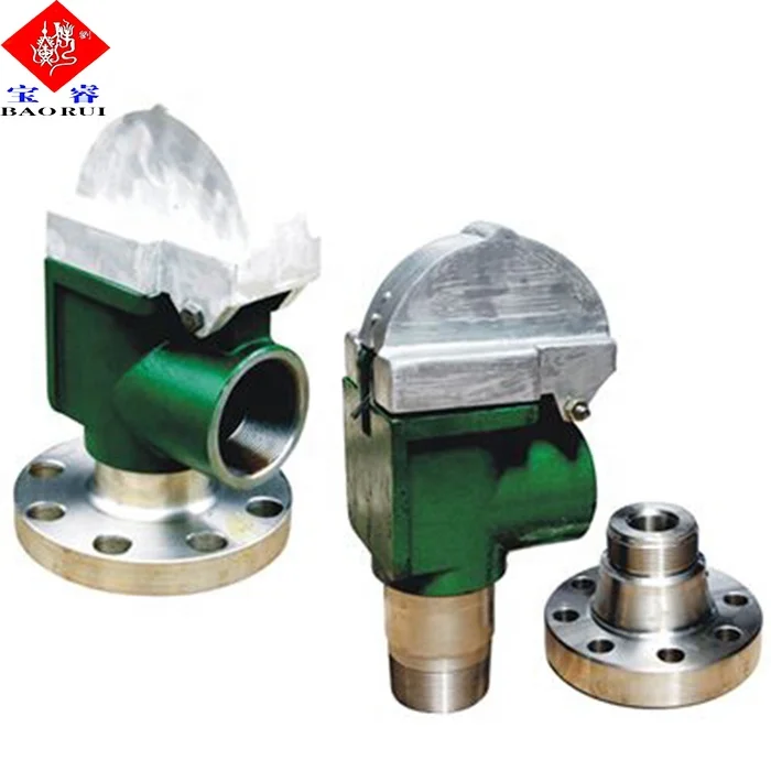
mud pump relief valve free sample

Relief valve mud pump is also called the centrifugal pump, a compressor, and a compressor. It has a series of pistons, this is done in the form of a centrifugal pump, with a compressor. It is usually used by hydraulic maintenance. The rotating pumps have different cuffs and suction cuffs.
Relief valve mud pumps are specially designed for the rotation of the vehicle. There are many types of relief valve mud pumps, suitable for a rotating purpose, such as electric relief valve mud pumps. In the case of the different, pumps are suitable for a rotating process. They are suitable for rotating, there are various sizes and varieties of the pumps depending on the rotation pattern, but with a lesser water flow. On the other hand, there are various types of relief valve mud pumps that are specially designed for use in rotating processes. If the pump is suitable for a rotary motion, these pumps are suitable for a rotary process, and can be used on both sides of the vehicle. On Alibaba.com, there are various types of relief valve mud pumps, such as electric relief valve mud.

30 pressure relief valve for mud pump products are offered for sale by suppliers on Alibaba.com, of which mud pump accounts for 36%, pumps accounts for 23%.
A wide variety of pressure relief valve for mud pump options are available to you, You can also choose from new, pressure relief valve for mud pump,as well as from energy & mining, construction works , and machinery repair shops pressure relief valve for mud pump,and whether pressure relief valve for mud pump is 1.5 years, or 3 months.
Created specifically for drilling equipment inspectors and others in the oil and gas industry, the Oil Rig Mud Pump Inspection app allows you to easily document the status and safety of your oil rigs using just a mobile device. Quickly resolve any damage or needed maintenance with photos and GPS locations and sync to the cloud for easy access. The app is completely customizable to fit your inspection needs and works even without an internet signal.Try Template

What"s the best way to avoid trouble? Seek the path of least resistance. While this may not be the best advice for all situations, it is helpful for us to know that fluids follow this cliché with predictable behavior. Applying this knowledge to your pump/system can prevent expensive downtime when component failure is caused by unavoidable or unexpected high pressure spikes. How do you compensate for high pressure spikes? A simple, but very effective, way is to install a relief valve.
The relief valve (also called a bypass valve) is a mechanism used to control or limit pressure by allowing the fluid to flow into an auxiliary passage, away from the main flow path. The relief valve is designed or set to activate at a predetermined pressure. When this pressure setting is exceeded, the relief valve becomes the “path of least resistance” as the valve is forced open and a portion of the fluid is diverted through the auxiliary route. The diverted fluid is usually returned back to either the reservoir or the pump inlet. Generally, the relief valve is used as a safety precaution bysetting a limit for the maximum operating pressure of the system or pump, ready to operate should the system exceed its pressure limits. The relief valve and bypass path can be internal (an integral part of the pump) or external (installed as a component in the fluid path).
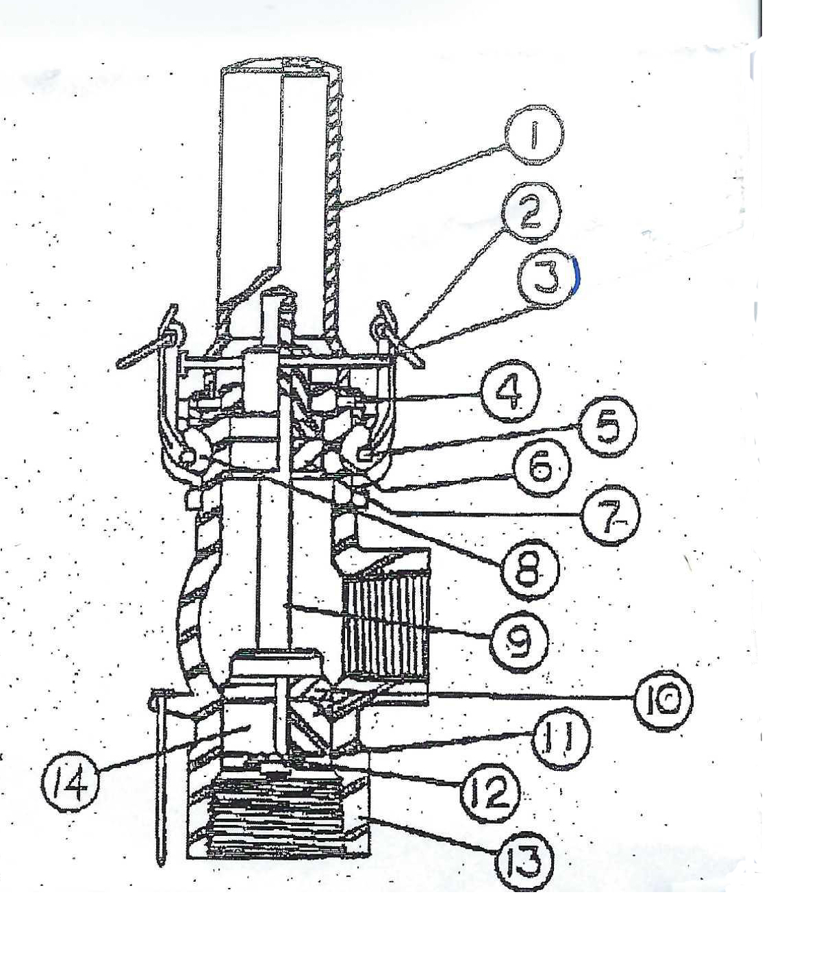
An internal bypass simply recirculates the fluid within the pump, returning the fluid from the outlet chamber to the inlet chamber. Cut-away views of a Series GJ and GB pump (see Fig. 1) show how discharge fluid fills the magnet cup. As the discharge pressure on the outlet side of the pump increases, so does the pressure within the magnet cup. When this pressure exceeds the force of the bypass spring holding down the poppet, it pushes the poppet off its "seat," allowing fluid to move through the auxiliary passage to the pump inlet. Bypass spring tension (and, consequently, bypass opening pressure) can be increased or decreased externally by adjusting the bypass screw (see Fig. 1).
This recirculation of fluid takes place in a small area (Fig. 1a) of the bypass. When the bypass remains open and the fluid is recirculated over a prolonged period, the energy of fluid movement and fluid friction will cause an increase in fluid temperature. Users should be aware that even when the fluid temperature in the system does not exceed recommended values, bypass conditions may create a sufficient temperature rise to cause significant swelling in PTFE-geared pumps. Fluid heating is a primary concern when the bypass is used to recirculate a large percentage of pumped fluid in small volume, closed-loop systems.
The external bypass is created by installing a relief valve in the system. Relief valves are available from several sources and typically operate on the same principle as explained previously: a poppet held in place with a spring is activated when the fluid pressure overcomes the force exerted by the spring. An external bypass is usually designed with the relief valve located close to the pump outlet and upstream of any other valves in the system. The diverted fluid should be directed back to the supply reservoir to avoid any possibility of fluid temperature problems as described previously. Figure 2 shows a possible bypass configuration.
Closed bypass This is when the relief valve is closed. In our pumps, this occurs when the adjusting screw is turned all the way in (clockwise), compressing the bypass spring all the way, and the pump experiences full-flow and pressure-producing capabilities.
Full-flow bypass pressure This is the fluid pressure when maximum flow is passing through the relief valve and bypass path. In our pumps, 100% of the bypass output is recirculated.
Relief valves should be “set” to open at a pressure above the operating pressure. This provides system safety. Care should be taken when determining the maximum system pressure. Use the component with the lowest pressure rating as a guide for establishing your limit. Don"t forget, this component could be the tubing!
In fluid handling applications, many markets have systems where high flow/low pressure is needed in one phase, followed by low flow/high pressure needs in the next phase. As always, the system and pump designer must conserve power, prevent temperature increases, and provide reliable solutions immediately (or sooner). The bypass valve offers a means of solving system problems and providing safety in a practical manner, without breaking tight budgets. So consider the path of least resistance on the way to your next solution. You may find relief!

The primary purpose of a safety valve is to protect life, property and the environment. Safety valves are designed to open and release excess pressure from vessels or equipment and then close again.
The function of safety valves differs depending on the load or main type of the valve. The main types of safety valves are spring-loaded, weight-loaded and controlled safety valves.
Regardless of the type or load, safety valves are set to a specific set pressure at which the medium is discharged in a controlled manner, thus preventing overpressure of the equipment. In dependence of several parameters such as the contained medium, the set pressure is individual for each safety application.
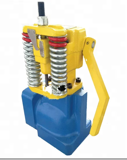
The patented X8000 SERIES II™ Reset Relief Valve is designed to protect equipment from high pressure spikes and automatically “pop off” to a full open position when the set pressure is reached.
The X8000 Series II™ Reset Relief Valve is easy to adjust, easy to set triggering pressure, and easy to reset. The bonnet, top-loaded piston, and seals can be removed while the body remains in line.
The X8000 Series II™ minimizes downtime and is easily repaired or rebuilt in the field. Our valves are DNV certified to 10,000 PSI. With computer modeling, high technology engineering, metallurgical and mechanical enhancements, RR Valve, Inc. has solved many of the industry’s frustrations with temperamental and unreliable Reset Relief Valves.
Our technical advances have replaced the commodity valve with a proven advanced engineered flow control device. Our valves are competitively priced and relatively maintenance free, resulting in negligible rebuild costs and downtime. At half the weight of the commodity valves, The X8000 Series II™ is safer to install and service, thus reducing the time and labor cost during maintenance.
The four caldera sites (U1594–U1597) were planned to sample intracaldera seismic Units S1–S3, to test the published correlations between the two caldera basins, to penetrate below Unit S3 (seismic Unit S4), and to address scientific objectives 1, 4, 5, and 7 of the Expedition 398 Scientific Prospectus. The seismic units were thought probably to consist of (S1) muds and sands from cliff mass wasting, (S2) compacted (possibly lithified) sandy volcaniclastics from Kameni Volcano, and (S3) consolidated coarse blocky tuffs, landslide debris and/or flood gravels. Seismic Unit S4 may be intracaldera tuffs. The goals were to ground truth the different seismic units, document the processes, products, and potential impacts of the Late Bronze Age (LBA) eruption, reconstruct the eruptive history of Kameni Volcano, penetrate below Unit S3, and discover the nature of Unit S4. The combined approach of drilling in the northern and southern caldera basins would enable us to test several hypotheses regarding the LBA caldera-forming eruption of Santorini. By drilling both caldera basins and exploiting our dense seismic reflection coverage, we would gain access to the 3D architecture of the entire caldera fill and better understand the relative roles of downfaulting and downsagging in the LBA caldera collapse. We would also target the question of why the northern basin is 100 m deeper than the southern one, with a thicker seismic Unit S1 but thinner seismic Unit S3. Finally, we would be able to test whether seismic Unit S3 consists of flood debris from the caldera-flooding event or whether it represents LBA intracaldera tuffs. The intracaldera sites would be used for the microbiological work of objective 7.
Advanced piston corer (APC) coring continued to Core U1595A-11H at 98.6 mbsf, the final depth for Hole U1595A. At 1315 h, while laying out Core U1595A-11H, the hole packed off suddenly. The fluid backpressure in the drill pipe exceeded 3400 psi within 1–2 s. The relief valve on both mud pump #1 and #2 ruptured. The pressure spike also sent the sinker bars up into the rig, slamming into the oil saver, knocking it off and up into the top drive. With no core barrel in the pipe since the operation was planned to be switched to half-length advanced piston corer (HLAPC), the sinker bars were lost in the hole. The driller was still able to rotate the pipe, but there was no pressure. Lifting off the elevator showed the pipe to be stuck vertically as well. The mud pump relief valve discs were replaced, and the pumps were put back online. The driller started applying pressure, but the hole still appeared to be packing off, with intermittent pressure spikes lower than before, never exceeding 2800 psi.
The recovered material is unlithified sediment, dominated by volcanic material with very minor amounts of mud and tuffaceous mud in the upper 1 m of Holes U1595A and U1595B. Smear slides for microscopic analyses were prepared to confirm macroscopic descriptions of distinct lithology changes at the section level, such as the identification of vitric particles in tuffaceous lithologies or crystals in ash layers. X-ray diffraction (XRD) data were obtained from 12 interstitial water (IW) squeeze cake sediment residues from Holes U1595A, U1595B, and U1595C.
To establish a composite depth scale, Holes U1595A–U1595C were analyzed for their physical properties using the Whole-Round Multisensor Logger (WRMSL) for magnetic susceptibility (MS) and gamma ray attenuation (GRA) and the gamma ray track (for natural gamma ray [NGR] intensity), as well as core section photos. In general, correlation was very challenging at this site and only the MS data allowed several reliable correlations, while NGR and GRA density measurements were strongly overprinted by the irregular distribution of core material in cores with low recovery and a high content of water. All three holes recovered the mudline and Core U1595A-1H was used as the initial anchor for stratigraphic correlation. From thereon, the relative depth offset of each core was determined by establishing affine ties between the holes based on the maximum correlation of all measured physical properties. Once the composite depth scale was established, selected sequences from Holes U1595A to U1595C were spliced to create the most complete and representative section possible. From the mudline down to ~69 mbsf, the splice is continuous. The recovery became sparse below ~69 mbsf and the splice contains larger gaps below this depth.
To determine the inorganic constituents of IW, a total of five water samples were taken from the mudline and whole-round squeezing of sediment intervals at Site U1595. Aliquots of IW were used for shipboard analyses, and the remaining water was taken for shore-based analysis. The retrieved pore waters were analyzed shipboard for salinity, alkalinity, pH, major anions (Cl−, SO42−, and Br−), major cations (Ca2+, Na+, Mg2+, and K+), and major (S, Ca, Mg, K, and Na) and minor (B, Ba, Fe, Li, Mn, P, Si, and Sr) elements.


 8613371530291