
mud pump strainer free sample

Explore a wide variety of mud pump discharge strainer on Alibaba.com and enjoy exquisite deals. The machines help maintain drilling mud circulation throughout the project. There are many models and brands available, each with outstanding value. These mud pump discharge strainer are efficient, durable, and completely waterproof. They are designed to lift water and mud with efficiency without using much energy or taking a lot of space.
The primary advantage of these mud pump discharge strainer is that they can raise water from greater depths. With the fast-changing technology, purchase machines that come with the best technology for optimum results. They should be well adapted to the overall configuration of the installation to perform various operations. Hence, quality products are needed for more efficiency and enjoyment of the machines" full life expectancy.
Alibaba.com offers a wide selection of products with innovative features. The products are designed for a wide range of flow rates that differ by brand. They provide cost-effective options catering to different consumer needs. When choosing the right mud pump discharge strainer for the drilling project, consider factors such as size, shape, and machine cost. More powerful tools are needed when dealing with large projects such as agriculture or irrigation.
Alibaba.com provides a wide range of mud pump discharge strainer to suit different tastes and budgets. The site has a large assortment of products from major suppliers on the market. The products are made of durable materials to avoid corrosion and premature wear during operations. The range of products and brands on the site assures quality and good value for money.
Our triplex and quintuplex pumps, cementing and fracturing equipments are interchangeable to global famous brands: Weir spm, Serva, BJ, Gardner Denver, Halliburton, Oilwell, OPI and so on. We also make a full line of Module assy and fluid end expendables for popular mud pumps in the world, including continental Emsco, National, Gardner Denver, Oilwell, Ideco, Wheatly, Wilson,with, opi, Ellis Williams, etc.
System designers frequently place strainers on the suction side of a pump. This practice, ostensibly based on good intentions, is rarely a good idea and will create serious issues for the pump from the aspect of reduced and turbulent flow, inadequate net positive suction head available (NPSHa) and eventually blocked flow.
There are several acceptable methods and alternative designs to avoid these issues. There are also situations where placing the strainer on the suction side is the right thing to do, but it must be done correctly.
Normally the reasons for placing the strainer on the suction side of a pump seem like good ones, as it is prudent to protect the pump and the other ancillary components in the system.
This preventative design approach can work to preclude or mitigate fouling of heat exchangers, valve blockages and other component issues with small operating clearances and annulus voids, to name a few. In the case of some positive displacement pump types such as gear and screw pumps, it is imperative.
The first issue is that the strainer will inevitably clog. The clogging will reduce, and at some rate of closure, completely shut off flow to the pump suction, creating serious damage to the pump. The blockage also creates issues with the system and downstream components that rely on the flow provided by the pump. Example: another pump in series with the first pump.
The second issue is a marked reduction in NPSHa. The formula for NPSHa is shown below for reference. Every pump has a requirement for a given amount of suction energy that is referred to as net positive suction head required (NPSHr). The specific requirement is determined by the manufacturer and is published on their performance curves. The NPSHr data is determined by empirical means.
If you have read some of my previous articles, you already know that the suction side of the system must provide energy to deliver the liquid to the pump. The pump does not reach out and pull the fluid into the impeller. The pump does not suck the fluid into itself, as fluids do not have tensile strength. The suction system must provide a level of NPSHa. The level of NPSHa is either calculated or measured by the owner or operator of the system. It is imperative that there is more NPSHa than NPSHr. This difference is referred to as the margin. The Hydraulic Institute (HI) and American National Standards Institute (ANSI) have a published standard that covers this subject—ANSI/HI 9.6.1-2012.
The friction component of the NPSHa formula becomes increasingly large when the strainer becomes clogged. This is a negative component in the formula and as a result the reduction in available NPSH will cause the pump to cavitate.
If you look deeper into the cavitation phenomena, the reduction in flow caused by the restricted strainer will result in a higher velocity across the device. The fluid in the suction line must obey the law of conservation of energy, which states energy can neither be created nor destroyed, but it can be altered in form. This is best summarized in Bernoulli’s equation.
Bernoulli’s Law, simplified for this article, explains why the pressure will drop correspondingly as the velocity increases. The clogged strainer is why the velocity has increased in the first place. As the pressure drops, the vapor pressure will also be affected, and it is possible at some point for the liquid to change state and form a vapor. Centrifugal pumps are not capable of pumping air, vapor or non-condensable gases. If there is as little as 4 percent entrainment in the liquid, it can bind (vapor lock) the pump.
In oil and gas applications where the pump is upstream at the well head, there is simply no way to avoid the introduction of solid containments and dual phase fluids to the pump suction. It is extremely rare that a fluid coming out of the ground will be 100 percent gas free. A centrifugal pump cannot pump (compress) air or gas.
The comparative difference in the range of fluid densities is a factor of approximately 800. Different designs and sizes of pumps handle this issue in better ways than others, but at some level all centrifugal pumps will vapor lock and fail. The impeller eye will become blocked by the air, vapor or gas.
If the pump is a self-primer or simply a centrifugal pump placed in a lift condition application (externally primed), there can or will be performance issues should any restriction be placed in the suction line. Note that “lift” signifies that the level of the source liquid to be pumped is below the centerline of the pump impeller. The available NPSH will already be low because the static head component in the formula is now a negative quantity due to the lift condition. Further restrictions will add to the negative component of friction and for any temperature above ambient the vapor pressure component will also work against the pump.
If there are strainers on the suction side of the pump, the best step you can take is to add instrumentation and continuously monitor the differential pressure (DP) across the strainer. The strainer will have a resistance coefficient assigned by the manufacturer. This is a great place to use an automated alarm system. The DP across the strainer for both clean and dirty conditions should be known. There must be a low value of DP for the new and clean strainer; I prefer less than 2 pounds per square inch gauge (psig). Also, you can compare the low clean value of DP to a higher value for a clogged strainer as indication for action.
Note: You have to know the head loss across the strainer anyway to do the NPSHa calculation. How else would you know if there is sufficient margin in your design?
If the DP across the strainer is not automatically monitored and alarmed, then an operator must check on a scheduled basis. All changes must be recorded and action must be taken if the DP is out of specification. Even a difference of 1 or 2 psig DP can be the difference between success and failure.
Some of the better designs incorporate a duplex strainer arrangement so that one strainer can be offline for cleaning and maintenance with no disruption in service. Some designs automatically change over and clean with no operator action required.
The size of the suction pipe must have an adequate diameter to keep friction losses down and velocities in an acceptable range. I always recommend to keep liquid velocities on the suction side below 2 meters per second (6.6 feet per second) at the maximum, and one meter per second (3.3 feet per second) is better. Just as the suction pipe size must be adequate, so must the strainer size.
Strainers should be engineered and selected to keep the pressure drop down to an acceptable low and safe level. The industry rates strainers using “CV”—known as the flow coefficient. When selecting strainers, I suggest you work with a knowledgeable expert, because the selection process can be tricky for the uninitiated. Most strainer resistance coefficients are based on water and a given mesh size for the strainer screen. You may need to correct for viscosity and a different mesh depending on your fluid properties. You will also need to decide the capacity ratio known as open area ratio (OAR). The OAR will indicate how long you can operate the strainer before it will require cleaning or replacement.
In a good system design, the pump should be positioned close to the suction source, but there should also be at least 5 to 10 pipe diameters worth of straight, unobstructed piping connecting to the pump. Never connect any components such as an elbow, reducer, valve or strainer within the final run of pipework. A clogged strainer will present a turbulent flow profile to the pump suction. If you connect an elbow directly to the pump flange, the fluid will be forced toward the outside of the elbow and will not be directed into the center of the impeller. Most pumps are designed for fluid to be evenly loaded at the center of the impeller. Otherwise, the imbalance creates stress on the pump’s bearings and seals that leads to wear and premature failure.
It is noted and acknowledged that many processes are purposely designed to have strainers on the suction side of the pump. Some processes actually rely on the reduced pressure (vacuum) created in the process. An example would be a filter press. Note these systems and pumps are designed and instrumented for the additional stress.
Every rule usually has exceptions, but from the perspective of an industry best practice, I suggest thinking long and hard before the placement of strainers on the suction side of the pump—and you “exceptions” already know who you are.
Many pumps are designed to handle some amount and size of solids. The manufacturer can or will advise what size solids the pump will handle. It is typically a better idea to place the strainer on the discharge side of the pump if possible. If you must place the strainer on the suction side for a valid design reason, then take the proper steps to design the system to prevent pump issues caused by clogging.

Cavitation is an undesirable condition that reduces pump efficiency and leads to excessive wear and damage to pump components. Factors that can contribute to cavitation, such as fluid velocity and pressure, can sometimes be attributed to an inadequate mud system design and/or the diminishing performance of the mud pump’s feed system.
When a mud pump has entered full cavitation, rig crews and field service technicians will see the equipment shaking and hear the pump “knocking,” which typically sounds like marbles and stones being thrown around inside the equipment. However, the process of cavitation starts long before audible signs reveal themselves – hence the name “the silent killer.”
Mild cavitation begins to occur when the mud pump is starved for fluid. While the pump itself may not be making noise, damage is still being done to the internal components of the fluid end. In the early stages, cavitation can damage a pump’s module, piston and valve assembly.
The imperceptible but intense shock waves generated by cavitation travel directly from the fluid end to the pump’s power end, causing premature vibrational damage to the crosshead slides. The vibrations are then passed onto the shaft, bull gear and into the main bearings.
If not corrected, the vibrations caused by cavitation will work their way directly to critical power end components, which will result in the premature failure of the mud pump. A busted mud pump means expensive downtime and repair costs.
To stop cavitation before it starts, install and tune high-speed pressure sensors on the mud suction line set to sound an alarm if the pressure falls below 30 psi.
Although the pump may not be knocking loudly when cavitation first presents, regular inspections by a properly trained field technician may be able to detect moderate vibrations and slight knocking sounds.
Gardner Denver offers Pump University, a mobile classroom that travels to facilities and/or drilling rigs and trains rig crews on best practices for pumping equipment maintenance.
Severe cavitation will drastically decrease module life and will eventually lead to catastrophic pump failure. Along with downtime and repair costs, the failure of the drilling pump can also cause damage to the suction and discharge piping.
When a mud pump has entered full cavitation, rig crews and field service technicians will see the equipment shaking and hear the pump ‘knocking’… However, the process of cavitation starts long before audible signs reveal themselves – hence the name ‘the silent killer.’In 2017, a leading North American drilling contractor was encountering chronic mud system issues on multiple rigs. The contractor engaged in more than 25 premature module washes in one year and suffered a major power-end failure.
Gardner Denver’s engineering team spent time on the contractor’s rigs, observing the pumps during operation and surveying the mud system’s design and configuration.
The engineering team discovered that the suction systems were undersized, feed lines were too small and there was no dampening on the suction side of the pump.
Following the implementation of these recommendations, the contractor saw significant performance improvements from the drilling pumps. Consumables life was extended significantly, and module washes were reduced by nearly 85%.
Although pump age does not affect its susceptibility to cavitation, the age of the rig can. An older rig’s mud systems may not be equipped for the way pumps are run today – at maximum horsepower.
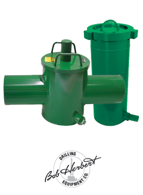
It may be impractical to flush system piping during drilling operations. However, strainer screens should be checked daily to remove any debris or other flow restrictions.

There are many different ways to drill a domestic water well. One is what we call the “mud rotary” method. Whether or not this is the desired and/or best method for drilling your well is something more fully explained in this brief summary.
One advantage of drilling with compressed air is that it can tell you when you have encountered groundwater and gives you an indication how much water the borehole is producing. When drilling with water using the mud rotary method, the driller must rely on his interpretation of the borehole cuttings and any changes he can observe in the recirculating fluid. Mud rotary drillers can also use borehole geophysical tools to interpret which zones might be productive enough for your water well.
The mud rotary well drilling method is considered a closed-loop system. That is, the mud is cleaned of its cuttings and then is recirculated back down the borehole. Referring to this drilling method as “mud” is a misnomer, but it is one that has stuck with the industry for many years and most people understand what the term actually means.
The water is carefully mixed with a product that should not be called mud because it is a highly refined and formulated clay product—bentonite. It is added, mixed, and carefully monitored throughout the well drilling process.
The purpose of using a bentonite additive to the water is to form a thin film on the walls of the borehole to seal it and prevent water losses while drilling. This film also helps support the borehole wall from sluffing or caving in because of the hydraulic pressure of the bentonite mixture pressing against it. The objective of the fluid mixture is to carry cuttings from the bottom of the borehole up to the surface, where they drop out or are filtered out of the fluid, so it can be pumped back down the borehole again.
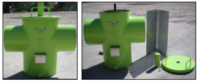
When using the mud rotary method, the driller must have a sump, a tank, or a small pond to hold a few thousand gallons of recirculating fluid. If they can’t dig sumps or small ponds, they must have a mud processing piece of equipment that mechanically screens and removes the sands and gravels from the mixture. This device is called a “shale shaker.”
The driller does not want to pump fine sand through the pump and back down the borehole. To avoid that, the shale shaker uses vibrating screens of various sizes and desanding cones to drop the sand out of the fluid as it flows through the shaker—so that the fluid can be used again.
Some drillers use compressed air to blow off the well, starting at the first screened interval and slowly working their way to the bottom—blowing off all the water standing above the drill pipe and allowing it to recover, and repeating this until the water blown from the well is free of sand and relatively clean. If after repeated cycles of airlift pumping and recovery the driller cannot find any sand in the water, it is time to install a well development pump.
Additional development of the well can be done with a development pump that may be of a higher capacity than what the final installation pump will be. Just as with cycles of airlift pumping of the well, the development pump will be cycled at different flow rates until the maximum capacity of the well can be determined. If the development pump can be operated briefly at a flow rate 50% greater than the permanent pump, the well should not pump sand.
Mud rotary well drillers for decades have found ways to make this particular system work to drill and construct domestic water wells. In some areas, it’s the ideal method to use because of the geologic formations there, while other areas of the country favor air rotary methods.
To learn more about the difference between mud rotary drilling and air rotary drilling, click the video below. The video is part of our “NGWA: Industry Connected” YouTube series:


 8613371530291