
mud pump system free sample

The 2,200-hp mud pump for offshore applications is a single-acting reciprocating triplex mud pump designed for high fluid flow rates, even at low operating speeds, and with a long stroke design. These features reduce the number of load reversals in critical components and increase the life of fluid end parts.
The pump’s critical components are strategically placed to make maintenance and inspection far easier and safer. The two-piece, quick-release piston rod lets you remove the piston without disturbing the liner, minimizing downtime when you’re replacing fluid parts.

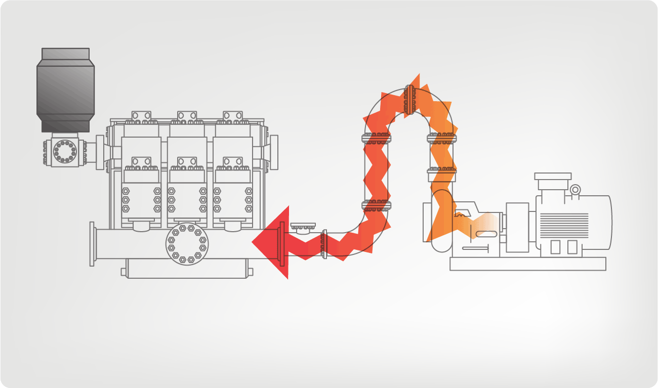
I’ve run into several instances of insufficient suction stabilization on rigs where a “standpipe” is installed off the suction manifold. The thought behind this design was to create a gas-over-fluid column for the reciprocating pump and eliminate cavitation.
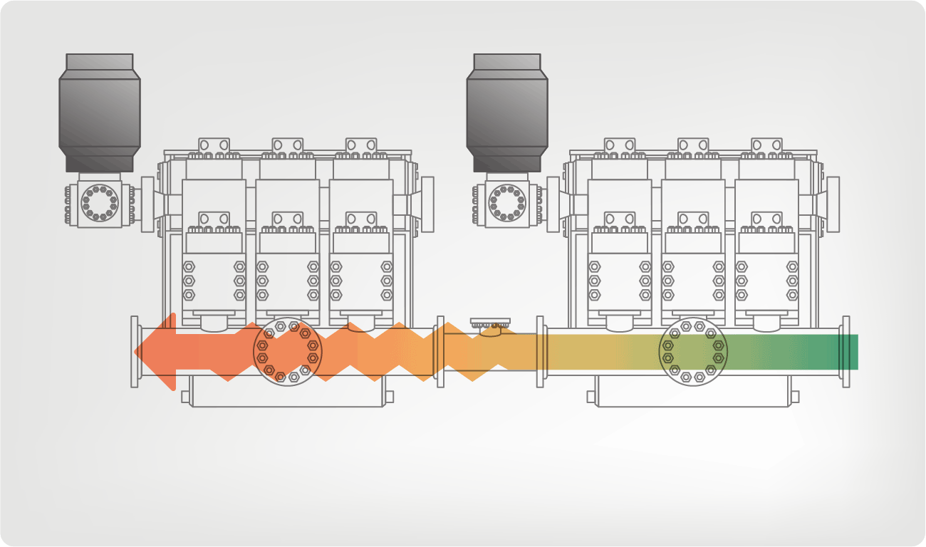
When the standpipe is installed on the suction manifold’s deadhead side, there’s little opportunity to get fluid into all the cylinders to prevent cavitation. Also, the reciprocating pump and charge pump are not isolated.
The gas over fluid internal systems has limitations too. The standpipe loses compression due to gas being consumed by the drilling fluid. In the absence of gas, the standpipe becomes virtually defunct because gravity (14.7 psi) is the only force driving the cylinders’ fluid. Also, gas is rarely replenished or charged in the standpipe.
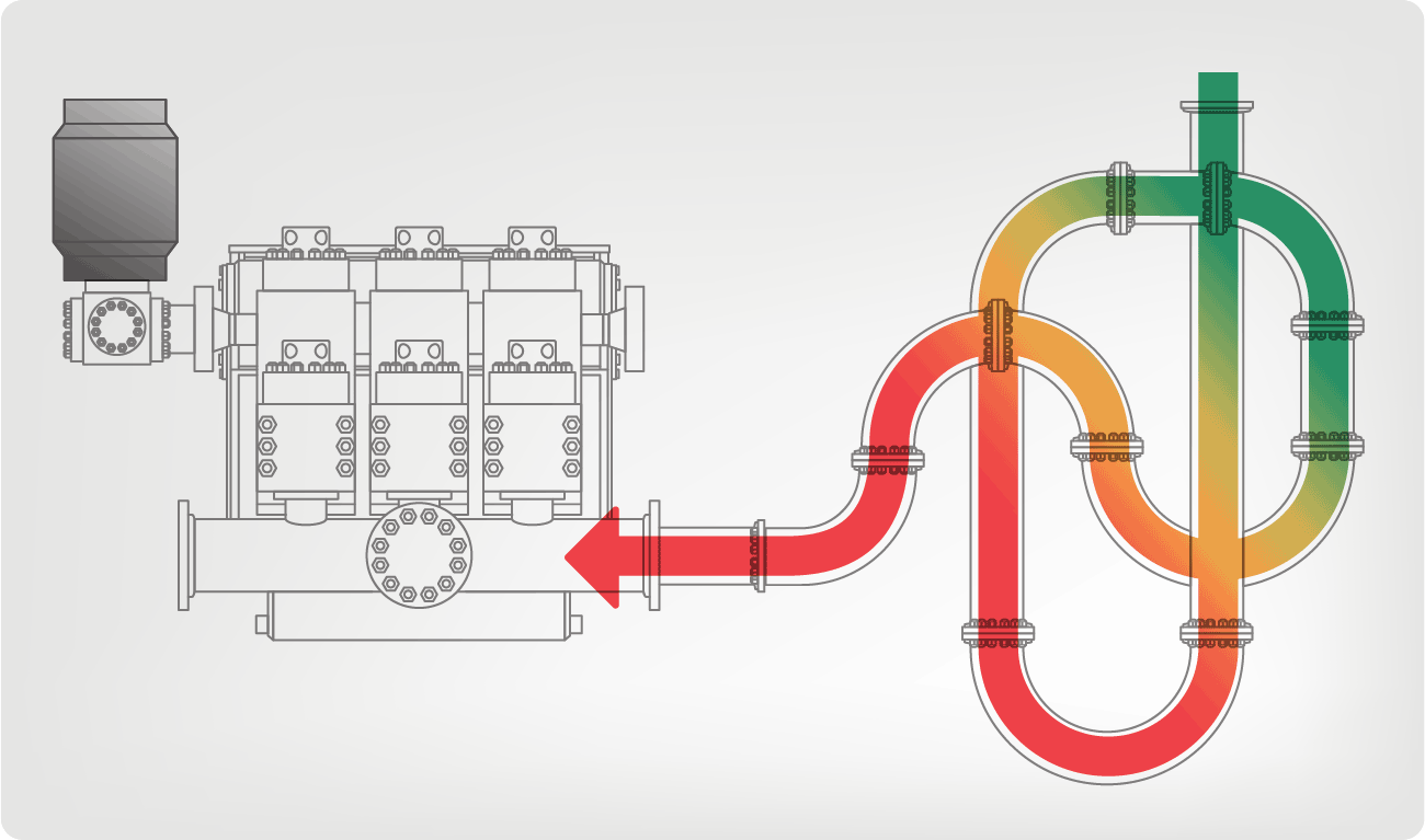
The suction stabilizer’s compressible feature is designed to absorb the negative energies and promote smooth fluid flow. As a result, pump isolation is achieved between the charge pump and the reciprocating pump.
The isolation eliminates pump chatter, and because the reciprocating pump’s negative energies never reach the charge pump, the pump’s expendable life is extended.
Investing in suction stabilizers will ensure your pumps operate consistently and efficiently. They can also prevent most challenges related to pressure surges or pulsations in the most difficult piping environments.
This invention relates to communication systems, and more particularly, to systems and methods for receiving and interpreting data signals being transmitted to the surface of the earth in a logging-while-drilling system.
The most common scheme for transmitting measurement information utilizes the drilling fluid within the borehole as a transmission medium for acoustic waves modulated to represent the measurement information. Typically, drilling fluid or "mud" is circulated downward through the drill string and drill bit and upward through the annulus defined by the portion of the borehole surrounding the drill string. The drilling fluid not only removes drill cuttings and maintains a desired hydrostatic pressure in the borehole, but cools the drill bit. In a species of the technique referred to above, a downhole acoustic transmitter known as a rotary valve or "mud siren", repeatedly interrupts the flow of the drilling fluid, and this causes a varying pressure wave to be generated in the drilling fluid at a frequency that is proportional to the rate of interruption. Logging data is transmitted by modulating the acoustic carrier as a function of the downhole measured data.
One difficulty in transmitting measurement information via the drilling mud is that the signal received is typically of low amplitude relative to the noise generated by the mud pumps which circulate the mud, as the downhole signal is generated remote from the uphole sensors while the mud pumps are close to the uphole sensors. In particular, where the downhole tool generates a pressure wave that is phase modulated to encode binary data, such as is disclosed in U.S. Pat. No. 4,847,815 and assigned to the assignee hereof, and where the periodic noise sources are at frequencies which are at or near the frequency of the carrier wave (e.g. 12 Hz), difficulties arise.
Mud pumps are large positive displacement pumps which generate flow by moving a piston back and forth within a cylinder while simultaneously opening and closing intake and exhaust valves. A mud pump typically has three pistons attached to a common drive shaft. These pistons are one hundred and twenty degrees out of phase with one another to minimize pressure variations. Mud pump noise is caused primarily by pressure variations while forcing mud through the exhaust valve.
The fundamental frequency in Hertz of the noise generated by the mud pumps is equal to the strokes per minute of the mud pump divided by sixty. Due to the physical nature and operation of mud pumps, harmonics are also generated, leading to noise peaks of varying amplitude at all integer values of the fundamental frequency. The highest amplitudes generally occur at integer multiples of the number of pistons per pump times the fundamental frequency, e.g., 3F, 6F, 9F, etc. for a pump with three pistons.
Mud pumps are capable of generating very large noise peaks if pump pressure variations are not dampened. Thus, drilling rigs are typically provided with pulsation dampeners at the output of each pump. Despite the pulsation dampeners, however, the mud pump noise amplitude is typically much greater than the amplitude of the signal being received from the downhole acoustic transmitter. To reduce or eliminate the mud pump noise so that the downhole signal can be recovered, different techniques have been proposed, such as may be found in U.S. Pat. Nos. 3,488,629 to Claycomb, 3,555,504 to Fields, 3,716,830 to Garcia, 4,215,425 to Waggener, 4,215,427 to Waggener et al., 4,262,343 to Claycomb, 4,590,593 to Rodney, and 4,642,800 to Umeda. What is common to all of the techniques is that they try to eliminate the mud pump noise by adding the mud pump noise to an inverted version of itself. Most of the techniques utilize two sensors in the mud stream (usually two pressure sensors) and take the difference of signals in an attempt to cancel the mud pump noise without canceling the data signal. Various of the techniques require particular physical arrangements.
The Umeda U.S. Pat. No. 4,642,800 takes a slightly different approach to eliminating mud pump noise. Umeda teaches that an average pump signature may be found by obtaining the pump signatures in the presence of data over a certain number of pump cycles. The updated average pump signature is corrected by interpolation to match the current pump cycle length and is subtracted from the current pump signature to provide the residual data signal. While the technique disclosed in Umeda may be effective for particular arrangements, it has several drawbacks. First, because Umeda averages pump signatures which include data pulses, unless the effect of the data signal over any averaging period is zero (i.e. non-carrier frequency systems), the data signal which is to be recovered will tend to be undesirably subtracted from itself. Second, because Umeda uses only a single strobe per pump cycle, estimates (e.g. interpolations) are utilized which can introduce significant error. Third, Umeda does not disclose in detail how to treat a multi-pump system. In particular, if Umeda assumes that the pump signature for each pump of a multi-pump system is the same as it would be for a single pump system, large errors are introduced in attempting to cancel out the pump noise, as pumps which are working in multi-pump systems will have different signatures than they would it they were working in a single pump system. In addition, because estimates are required for each pump in the multi-pump system, additional error in the multi-pump system is introduced.
It is therefore an object of the invention to provide methods and systems for accurately recovering data signals introduced into drilling mud in the presence of mud pump noise.
It is another object of the invention to provide methods and systems for accurately recovering logging-while-drilling (LWD) or measurement-while-drilling (MWD) information which is modulated in drilling mud by correlating mud pump piston positions to a mud pressure signature in a calibration procedure.
It is a further object of the invention to provide methods and systems for accurately obtaining LWD or MWD information in multiple mud pump systems by allocating noise attributable to each mud pump and by tracking the mud pump piston position of each mud pump.
Another object of the invention is to provide method and systems for recovering LWD or MWD information transmitted through drilling mud by varying the pressure of the drilling mud regardless of the manner in which the information is coded.
In accord with the objects of the invention, methods for recovering a LWD or MWD data signal in the presence of mud pump noise are provided, and generally comprise calibrating the drilling mud pressure as a function of the mud pump piston position, and then tracking the piston position during transmission of the LWD or MWD data signal and using the calibration information to subtract out the mud pump noise. More particularly, calibration is accomplished in the absence of the LWD or MWD data signal to provide a correlation between mud pump piston position and the drilling mud pressure; i.e., the pressure signature as a function of mud pump piston position is obtained. Then, when the LWD or MWD data signal is being provided, the mud pump piston position is tracked such that the pressure due to the pump can be subtracted; i.e., by knowing the mud pump piston position, the pressure due to the mud pump is found and subtracted from the total received signal to provide the LWD or MWD signal. Where a plurality of mud pumps are used, calibration is accomplished by running the mud pumps together in the absence of the LWD or MWD data signal, and processing the received mud pressure signals in the Fourier domain to allocated respective portions of the mud pressure signals to respective mud pumps such that each mud pump is provided with a signature as a function of its own piston position. With the piston position of each mud pump being tracked, the sum of the mud pressure signals generated by the mud pumps based on their piston positions is subtracted from the total received signal to provide the LWD or MWD signal.
According to a preferred aspect of the invention, the calibration procedure is periodically repeated, e.g., each time additional pipe is added to the drill string, thereby eliminating the effects of depth and mud property variation on the system.
FIGS. 8a, 8b, and 8c are respectively the total pump signal, and the signals from pump one and pump two in the multiple pump system calibrated according to FIGS 7a and 7b.
Referring to FIG. 1, the operation of the present invention in a typical drilling arrangement is illustrated schematically. Drilling mud 10 is picked up from mud pit 11 by one or more mud pumps 12 which are typically of the piston reciprocating type. The mud 10 is circulated through mud line 13, down through the drill string 14, through the drill bit 15, and back to the surface of the formation via the annulus 16 between the drill stem and the wall of the well bore 29. Upon reaching the earth"s surface 31, the mud is discharged through line 17 back into the mud pit 11 where cuttings of rock or other well debris are allowed to settle out before the mud is recirculated.
A downhole pressure pulse signaling device 18 is incorporated in the drill string for transmission of data signals derived during the drilling operation by the measurement instrument package 19. Signaling device 18 may be of the valve or variable orifice type which generates pressure pulses in the drilling fluid by varying the speed of flow. A preferred signaling device which generates sinusoidal signals is disclosed in U.S. Pat. No. 4,847,815 assigned to the assignee hereof. Data signals are encoded in a desired form by appropriate electronic means in the downhole tool. Arrows 21, 22, and 23 illustrate the path taken by the pressure pulses provided by the downhole signaling device 18 under typical well conditions. Pump 12 also produces pressure pulses in the mud line 13 and these are indicated by arrows, 24, 25, 26 and 26a which also illustrate the flow of the mud through the annulus 16.
In order for the downhole pressure pulse signals to be recoverable at the surface, some means must be provided to remove or substantially eliminate the portion of the mud pressure signal due to the mud pumps. Subsystem 30, including pressure transducer 32, mud pump piston position sensors 34, and computer or processor 36, comprises such a means.
The preferred pressure transducer 32 of subsystem 30 is a piezoelectric pressure transducer which provides an analog signal which is preferably bandpass filtered by a filter (not shown) or by the computer 36. The preferred mud pump piston position sensor 34 may either comprise an LVDT which utilizes a linear position transducer, or an RVDT which utilizes a rotary position transducer. The LVDT, as shown in FIG. 2a, has an arm 40a, a rod 42a, and a linear position transducer 44a with leads 46a. Arm 40a is coupled to one of the piston rods 47 of the mud pump 12 as well as to rod 42a of the LVDT. Rod 42a moves coaxially within the linear position transducer 44a, which provides a high precision digital indication of the location of piston 48 in the mud pump 12. The RVDT, as shown in FIG. 2b, has an arm 40b, a cable 42b, and an encoder or rotary position transducer 44b with a spring loaded sheave takeup reel 45b. The RVDT also includes leads 46b. Arm 40b of the RVDT of FIG. 2b is coupled to one of the piston rods 47 of the mud pump 12 as well as to the cable 42b of the RBDT. As arm 40b moves with the pump piston rod 47, the cable 42b is let out or reeled onto the takeup reel 45b takeup reel. The rotation of the takeup reel 45b provides a high precision digital indication of the location of piston 48 in the mud pump 12.
Testing has shown that the drilling mud pressure generated by the mud pump 12 is determined by the position of the mud pump piston for a given set of operating conditions. FIG. 3 illustrates how mud pump piston position correlates to mud pump noise. By coupling the linear position transducer 44a or rotary position transducer 44b to the piston rod 47 of the mud pump, a calibration can be performed that measures the pressure generated as a function of piston position.
The preferred calibration procedure for correlating mud pressure generated as a function of piston position for a single mud pump system is seen in FIG. 4. After the pump noise stabilizes in the system, and before the LWD and MWD tool turns on (i.e. before the data signal starts), the signals output by the position sensor 34 and the signals output by the pressure transducer 32 which are bandpass filtered at 39 are preferably recorded at 52 as related position and pressure arrays 55, 57 in the computer (e.g. in computer memory). Preferably, approximately eight seconds of data (e.g., five to ten pump cycles) are accumulated. Then, averages of the pressure as a function of position are calculated (thereby reducing random pressure variations) at 58 to produced a single position vs. pump noise calibration array 59. Indications of the average calibration array or the inverse thereof are stored and used for canceling mud pump noise as is hereinafter described.
The noise cancellation procedure according to the invention is set forth in FIG. 5. Upon the turning on of the downhole tool and the transmission of LWD or MWD data (hereinafter referred to simply as LWD data for sake of brevity), the position sensor 34 and pressure transducer 32 continue to provide indications of piston location and mud pressure; except that the piston position data is used in real time to determine the electrical signal (based on the calibration array 59) which must be subtracted from the composite LWD/noise signal to cancel the noise component of the signal and leave only the LWD signal. Thus, as shown in FIG. 5, the position sensor signal is sampled at 62 (i.e. based on the position sensor signal, the average calibration array is accessed and a corresponding pump noise is provided), and the corresponding pump noise pressure 64 is subtracted at 66 from the real time sensed pressure 32 which was bandpass filtered at 67 to eliminate high frequency components. The difference between the real time sensed pressure and the pump noise pressure provides an indication of the LWD data signal 68.
Test results of a real time sensed pressure pump noise signal are seen in FIG. 6a, where the amplitude of the signal as expressed in dB (in 10 dB increments) is plotted versus the frequency expressed in Hz (in 4 Hz increments). As seen in FIG. 6a, the noise signal includes several peaks having amplitudes between -10 dB and 0 dB, and even includes a peak having an amplitude exceeding 10 dB. The noise signal of FIG. 6a was then subjected to the noise cancellation procedure of FIG. 5. The noise signal remaining after mud pump noise cancellation is seen in FIG. 6b, and shows that the calibration and noise cancellation procedures reduced noise considerably. In fact, the largest remaining noise peak found at about 5 Hz, has an amplitude of approximately -15 dB, which is more than 25 dB less than the largest peak seen in FIG. 6a prior to noise cancellation.
Turing to FIGS. 7, 7a and 7b, a flow chart of the mud pump calibration procedure for a system utilizing two mud pumps is seen. After the pump noise stabilizes in the system, and before the LWD tool turns on (i.e. before the data signal starts), the signals output by each position sensor 34a, 34b and the signal output by the pressure transducer 32 and filtered at 39 by a bandpass filter which measures composite pump noise are recorded as related position arrays 55a, 55b and pressure array 57 in the computer (e.g. in computer memory). Preferably, approximately twelve seconds of data are accumulated in computer memory at 52; FIG. 8a showing an example of the analog pressure signal which is digitized and stored as part of the array. A fast Fourier transform (FFT) of the composite pump noise signal is then conducted at 70 by the computer. As a result of the FFT, the amplitude and phase of all frequencies contained in the composite mud pump noise signal is obtained at 70 (see FIG. 9a). Utilizing the operating speed of each pump which can be computed from the position sensor of each mud pump, the fundamental frequency and harmonics for each pump are calculated at 72. The, at 75, the amplitude and phase information for each fundamental and harmonic frequency are extracted from the FFT and assigned to its source (i.e. a particular one of the mud pumps) to provide results as seen in FIGS. 9b and 9c. Taking an inverse Fourier transform of the frequency spectra of FIGS. 9b and 9c at 76a and 76b, signals attributable to each of the pumps are obtained as seen in FIGS. 8b and 8c. As indicated in FIG. 7b at 58a and 58b, the position of each mud pump position sensor is related to the mud pressure generated by the respective mud pump, and an average of the pressure as a function of position is calculated for each mud pump to produce two position vs. pump noise calibration arrays 59a and 59b. Indications of the average calibration arrays are stored in computer memory and used for canceling mud pump noise as is described above with reference to FIG. 10.
Referring now to FIG. 10, the noise cancellation procedure for a system using multiple mud pumps is seen. Upon the turning on of the downhole tool and the transmission of LWD data, the position sensors 34a and 34b and pressure transducer 32 continue to provide indications of piston location and mud pressure; except that the piston position data is used in real time to determine the electrical signal (based on the calibration arrays 59a and 59b) which must be subtracted from the composite LWD/noise signal to cancel the noise component of the signal and leave only the LWD signal. Thus, as shown in FIG. 10, the position sensor signals are sampled at 62a and 62b (i.e. based on the position sensor signals, the average calibration arrays 59a and 59b are accessed and corresponding pump noises are provided), and the corresponding pump noise pressures 64a and 64b are subtracted at 66 from the real time sensed pressure 32 which was bandpass filtered at 67 to eliminate high frequency components. The difference between the real time sensed pressure and the pump noise pressures provides an indication of the LWD data signal 68. That signal is then decoded according to techniques known in the art which are not part of the present invention.
Test results of a real time sensed pressure containing pump noise for two mud pumps is seen in FIG. 11a where amplitude is plotted against frequency. As seen in FIG. 11a, numerous noise peaks having amplitudes of -20 dB or higher are seen, with the largest peak of about -5 dB at 5 Hz. The pressure signal obtained after utilizing the calibration and noise cancellation steps of FIGS. 7 and 10 in order to substantially cancel mud pump noise from the signal of FIG. 10a is seen in FIG. 10b. As seen in FIG. 10b, the remaining noise is substantially reduced relative to the noise of FIG. 10a, with the largest peak of about -18 dB occurring at approximately 18 Hz.
There have been described and illustrated herein methods and apparatus for canceling mud pump noise in order to recover a logging while drilling signal. While particular embodiments of the invention have been described it is not intended that the the invention be limited exactly thereto, as it is intended that the invention be as broad in scope as the art will allow. Thus, while particular pressure transducers, position sensors, pump-types, computers, FFT programs, and the like have been disclosed, it will be appreciated that other equipment and programs can be utilized effectively. Similarly, while certain preferred data gathering time periods were disclosed prior to running the LWD or MWD tool, it will be appreciated that other time frames could be utilized. Also, while the invention was described with reference to LWD and MWD procedures, it will be appreciated that the terms LWD and MWD are intended to include any other data signaling procedure where data is transmitted in drilling mud in the presence of mud pump noise. Further, while the invention was disclosed with reference to systems utilizing one or two mud pumps, it will be appreciated that the teachings equally apply to systems utilizing additional mud pumps. All that is required is that the pressure signature of each mud pump relative to its piston position be obtained via transforming the total signal into the Fourier domain, dividing the Fourier response among the various mud pumps based on their fundamental and harmonic frequencies, and converting the responses back into respective pressure signatures. It will be understood, of course, that where two mud pumps are working in unison (i.e. at the same frequency), their signatures can be treated together. Therefore, it will be apparent to those skilled in the art that other changes and modifications may be made to the invention as described in the specification without departing from the spirit and scope of the invention as so claimed.
Cavitation is an undesirable condition that reduces pump efficiency and leads to excessive wear and damage to pump components. Factors that can contribute to cavitation, such as fluid velocity and pressure, can sometimes be attributed to an inadequate mud system design and/or the diminishing performance of the mud pump’s feed system.
Although cavitation is avoidable, without proper inspection of the feed system, it can accelerate the wear of fluid end parts. Over time, cavitation can also lead to expensive maintenance issues and a potentially catastrophic failure.
When a mud pump has entered full cavitation, rig crews and field service technicians will see the equipment shaking and hear the pump “knocking,” which typically sounds like marbles and stones being thrown around inside the equipment. However, the process of cavitation starts long before audible signs reveal themselves – hence the name “the silent killer.”
Mild cavitation begins to occur when the mud pump is starved for fluid. While the pump itself may not be making noise, damage is still being done to the internal components of the fluid end. In the early stages, cavitation can damage a pump’s module, piston and valve assembly.
The imperceptible but intense shock waves generated by cavitation travel directly from the fluid end to the pump’s power end, causing premature vibrational damage to the crosshead slides. The vibrations are then passed onto the shaft, bull gear and into the main bearings.
If not corrected, the vibrations caused by cavitation will work their way directly to critical power end components, which will result in the premature failure of the mud pump. A busted mud pump means expensive downtime and repair costs.
To stop cavitation before it starts, install and tune high-speed pressure sensors on the mud suction line set to sound an alarm if the pressure falls below 30 psi.
Accelerometers can also be used to detect slight changes in module performance and can be an effective early warning system for cavitation prevention.
Although the pump may not be knocking loudly when cavitation first presents, regular inspections by a properly trained field technician may be able to detect moderate vibrations and slight knocking sounds.
Gardner Denver offers Pump University, a mobile classroom that travels to facilities and/or drilling rigs and trains rig crews on best practices for pumping equipment maintenance.
Severe cavitation will drastically decrease module life and will eventually lead to catastrophic pump failure. Along with downtime and repair costs, the failure of the drilling pump can also cause damage to the suction and discharge piping.
When a mud pump has entered full cavitation, rig crews and field service technicians will see the equipment shaking and hear the pump ‘knocking’… However, the process of cavitation starts long before audible signs reveal themselves – hence the name ‘the silent killer.’In 2017, a leading North American drilling contractor was encountering chronic mud system issues on multiple rigs. The contractor engaged in more than 25 premature module washes in one year and suffered a major power-end failure.
Gardner Denver’s engineering team spent time on the contractor’s rigs, observing the pumps during operation and surveying the mud system’s design and configuration.
The engineering team discovered that the suction systems were undersized, feed lines were too small and there was no dampening on the suction side of the pump.
Following the implementation of these recommendations, the contractor saw significant performance improvements from the drilling pumps. Consumables life was extended significantly, and module washes were reduced by nearly 85%.
Although pump age does not affect its susceptibility to cavitation, the age of the rig can. An older rig’s mud systems may not be equipped for the way pumps are run today – at maximum horsepower.
It may be impractical to flush system piping during drilling operations. However, strainer screens should be checked daily to remove any debris or other flow restrictions.
Heating, Ventilating and Air Conditioning General Office Area: The building shall be equipped with a combination heating, ventilation and air conditioning system. The system shall have ducted supply and return air. The space above the ceiling shall not be used as a supply or return plenum. The systems shall be sized in accordance with the weather conditions identified in Chapter 13, “Energy Conservation” of the 1996 BOCA Building Code and supplemented by the “Building Code Rules”. All HVAC equipment shall be commercial or light industrial grade. If new construction it shall be installed at grade or within mechanical rooms for easy access and maintenance. If existing construction, roof mounted equipment will be considered after all other options have been exhausted, including the elimination of noise and vibration transfer to the structural members. The HVAC systems shall be zoned, with units sized and placed as required by heating and cooling loads on the building. Zoning of systems is dependent on the size, shape and orientation of the building. The HVAC system shall be divided into a minimum of 4 exterior and 1 interior temperature control zones. Return air shall be taken from the area supplied or adjacent to the area in the same temperature control zone. The ventilation and exhaust system shall be sized to maintain a positive pressure throughout the building envelope to limit air and dust infiltration. No HVAC ductwork shall be installed under the floor slab or underground.
System Logging The system must maintain an automated audit trail which can 20 identify the user or system process which initiates a request for PHI COUNTY discloses to 21 CONTRACTOR or CONTRACTOR creates, receives, maintains, or transmits on behalf of COUNTY, 22 or which alters such PHI. The audit trail must be date and time stamped, must log both successful and 23 failed accesses, must be read only, and must be restricted to authorized users. If such PHI is stored in a 24 database, database logging functionality must be enabled. Audit trail data must be archived for at least 3 25 years after occurrence.

There are many different ways to drill a domestic water well. One is what we call the “mud rotary” method. Whether or not this is the desired and/or best method for drilling your well is something more fully explained in this brief summary.
One advantage of drilling with compressed air is that it can tell you when you have encountered groundwater and gives you an indication how much water the borehole is producing. When drilling with water using the mud rotary method, the driller must rely on his interpretation of the borehole cuttings and any changes he can observe in the recirculating fluid. Mud rotary drillers can also use borehole geophysical tools to interpret which zones might be productive enough for your water well.
The mud rotary well drilling method is considered a closed-loop system. That is, the mud is cleaned of its cuttings and then is recirculated back down the borehole. Referring to this drilling method as “mud” is a misnomer, but it is one that has stuck with the industry for many years and most people understand what the term actually means.
The water is carefully mixed with a product that should not be called mud because it is a highly refined and formulated clay product—bentonite. It is added, mixed, and carefully monitored throughout the well drilling process.
The purpose of using a bentonite additive to the water is to form a thin film on the walls of the borehole to seal it and prevent water losses while drilling. This film also helps support the borehole wall from sluffing or caving in because of the hydraulic pressure of the bentonite mixture pressing against it. The objective of the fluid mixture is to carry cuttings from the bottom of the borehole up to the surface, where they drop out or are filtered out of the fluid, so it can be pumped back down the borehole again.
When using the mud rotary method, the driller must have a sump, a tank, or a small pond to hold a few thousand gallons of recirculating fluid. If they can’t dig sumps or small ponds, they must have a mud processing piece of equipment that mechanically screens and removes the sands and gravels from the mixture. This device is called a “shale shaker.”
The driller does not want to pump fine sand through the pump and back down the borehole. To avoid that, the shale shaker uses vibrating screens of various sizes and desanding cones to drop the sand out of the fluid as it flows through the shaker—so that the fluid can be used again.
Gravel pack installed between the borehole walls and the outside of the well casing acts like a filter to keep sand out and maintain the borehole walls over time. During gravel packing of the well, the thin layer of bentonite clay that kept the borehole wall from leaking drilling fluid water out of the recirculating system now keeps the formation water from entering the well.
Some drillers use compressed air to blow off the well, starting at the first screened interval and slowly working their way to the bottom—blowing off all the water standing above the drill pipe and allowing it to recover, and repeating this until the water blown from the well is free of sand and relatively clean. If after repeated cycles of airlift pumping and recovery the driller cannot find any sand in the water, it is time to install a well development pump.
Additional development of the well can be done with a development pump that may be of a higher capacity than what the final installation pump will be. Just as with cycles of airlift pumping of the well, the development pump will be cycled at different flow rates until the maximum capacity of the well can be determined. If the development pump can be operated briefly at a flow rate 50% greater than the permanent pump, the well should not pump sand.
Mud rotary well drillers for decades have found ways to make this particular system work to drill and construct domestic water wells. In some areas, it’s the ideal method to use because of the geologic formations there, while other areas of the country favor air rotary methods.
To learn more about the difference between mud rotary drilling and air rotary drilling, click the video below. The video is part of our “NGWA: Industry Connected” YouTube series:

Created specifically for drilling equipment inspectors and others in the oil and gas industry, the Oil Rig Mud Pump Inspection app allows you to easily document the status and safety of your oil rigs using just a mobile device. Quickly resolve any damage or needed maintenance with photos and GPS locations and sync to the cloud for easy access. The app is completely customizable to fit your inspection needs and works even without an internet signal.Try Template

This present invention is directed to drilling wellbores in the earth, to systems for pumping drilling fluid (“mud”) for such operations, to mud pumping system modules with surge suppressing dampeners, and to methods of their use. DESCRIPTION OF THE RELATED
Known references disclose a wide variety of drilling systems, apparatuses, and methods including, but not limited to, the disclosures in U.S. Pat. Nos. 6,944,547; 6,918,453; 6,802,378; 6,050,348; 5,465,799; 4,995,465; 4,854,397; and 3,658,138, all incorporated fully herein for all purposes. Prior references disclose a wide variety of drilling fluid pumps (“mud pumps”) used in drilling operations and pump systems, for example, and not by way of limitation, those pumps and systems disclosed in U.S. Pat. Nos. 6,257,354; 4,295,366; 4,527,959; 5,616,009; 4,242,057; 4,676,724; 5,823,093; 5,960,700; 5,059,101; 5,253,987; in U.S. application Ser. No. 10/833,921 filed Apr. 28, 2004(all said U.S. references incorporated fully herein for all purposes). Known references disclose a variety of dampeners, accumulators, and surge suppressors; including, but not limited to, those disclosed in U.S. Pat. Nos. 4,299,253; 4,195,668; 2,757,689; 2,804,884; 3,674,053; 3,169,551; 3,674,053; 3,162,213; 2,380,866; 2,378,467; 2,397,248; 2,397,796; and 2,773,455—all incorporated fully herein for all purposes.
A drill bit carried at an end of a drillstring is rotated to form wellbores in the earth. Certain drillstrings include tubulars which may be drill pipe made of jointed sections or a continuous coiled tubing and a drilling assembly that has a drill bit at its bottom end. The drilling assembly is attached to the bottom end of the tubing or drillstring. In certain systems, to drill a wellbore, the drill bit is rotated (e.g., by a top drive, a power swivel, a rotary table system, or by a downhole mud motor carried by the drilling assembly). Drilling fluid, also referred to as “mud,” is pumped through the wellbore under pressure from a pit or container at the surface by a pumping system at the surface.
In certain known mud pump systems, suction and discharge modules have valves therein that selectively control fluid flow through the module in an intake (suction) mode in which piston apparatus creates a vacuum drawing drilling fluid into the module and in an output mode (Discharge) in which the piston apparatus creates pressure forcing drilling fluid out of the module. In the suction mode, a suction valve opens allowing drilling fluid into the module while a discharge valve remains closed. In the discharge mode, the pressure of the drilling fluid closes the suction valve and opens the discharge valve.
Both valves, the suction valve and the discharge valve, are subjected to the erosive and damaging effects of the flow of drilling fluid. The drilling fluid contains drilled cuttings and debris which can erode valve parts (e.g. seats, stems, valve members, seals, guide bushings, insert, liners, wear plates etc.). Also, mud pumps which can pump relatively hot drilling fluid at, e.g., 500 to 2000 gallons per minute, force the erosive drilling fluid against the valve parts at high velocities which add to the fluid"s damaging effects.
In many valves used in mud pump systems, a guide in the valve which is disposed across a flow path or guide fingers extending from a valve member into a valve seat guide a valve member so that valve member seats correctly and effectively against the valve seat. In many valves, the valve seat surface against which the valve member (or poppet) seats is, ideally, flat; and the surface of the valve member which sealingly abuts the flat seat surface of the valve seat is, correspondingly, and ideally, flat. A guide or guide fingers facilitates correct seating of the valve member"s flat seating surface against the valve seat"s flat seat surface. If either surface is not flat, or if one surface does not contact the other in a substantially parallel (flat surface to flat surface) manner, ineffective or inefficient valve operation may result.
In many known mud pump valves, the valves are opened and closed by mechanically creating a vacuum or fluid pressure increase in the valve that overcomes a spring to allow a valve member to move. The movement of the valve member is not controlled, i.e., it is subject to a surge of fluid under pressure. As fluid pressure builds up to move a valve member, a corresponding amount of fluid builds up adjacent the valve. when the pressure is high enough, a relatively large charge of fluid goes through the valve at high velocity. This surge of fluid can have deleterious effects on valve parts. BRIEF SUMMARY OF THE INVENTION
The present invention, in at least certain embodiments, discloses systems for pumping a drilling fluid mixture, the drilling fluid mixture containing drilling fluid and solids, the systems having: a pump apparatus; the pumping apparatus having a body with a pumping chamber, an inlet and an outlet; a suction valve in the body for selectively controlling flow of the drilling fluid mixture in through the inlet; a discharge valve in the body for selectively controlling flow of the drilling fluid mixture out through the outlet; and a dampener system according to the present invention in fluid communication with the pumping chamber.
Such a pump system according to the present invention, in one aspect, includes: a base; a housing connected to the base, the housing having an interior; a liner within the housing, the liner expandable in response to fluid pressure; a piston/cylinder apparatus in fluid communication with the housing; the piston/cylinder apparatus having a movable piston movable in response to fluid flowing from the housing to the piston/cylinder apparatus; a torsion apparatus movably connected to the base, the piston movable to contact and to move the torsion apparatus in response to fluid flowing from the housing to the piston/cylinder apparatus; and the torsion apparatus movable by the piston from a first static position to a second position to dampen pulsations of fluid into the pumping chamber.
In one aspect, a pumping system according to the present invention has a dampener system according to the present invention which includes: a housing, the housing having an interior; a deformable bladder within the housing, the deformable bladder in fluid communication with the pumping chamber; and the deformable bladder deformable in response to pressure variation in the pumping chamber.
The present invention discloses, in certain aspects, dampeners for drilling fluid pumping systems which suppress and/or eliminate the damaging effects of undesirable pulsations or surges of drilling fluid passing through the systems. In certain aspects, the dampener has a liner with liquid therein which expands and contracts in response to the pressure of drilling fluid passing through a pumping system.
The present invention discloses, in certain aspects, dampeners for drilling fluid pumping systems in which the dampener has a liner with liquid therein which expands and contracts in response to the pressure of drilling fluid passing through a pumping system. In certain aspects, a dampener according to the present invention has a torsion apparatus that absorbs and then releases energy to facilitate the dampening of drilling fluid surges. In other aspects, a dampener system according to the present invention has an inflatable bladder surrounded by an expandable spring member, both the bladder and the spring member responsive to drilling fluid surges to suppress deleterious effects of such surges.
The present invention discloses, in certain aspects, modules for a drilling fluid pumping system which include a dampener for suppressing and/or eliminating the damaging effects of undesirable pulsations or surges of drilling fluid passing through the modules. In certain aspects, the dampener is within a block of the module that also contains suction and discharge valve assemblies within a module block.
The present invention discloses, in certain aspects, a drilling fluid pumping system, also known as a mud pump system, for pumping drilling fluid or mud used in wellbore operations which has pumping modules with valves that have non-flat seating surfaces. In certain aspects, such valves have a valve member or poppet that is movable with multiple degrees of freedom in any of which effective seating of the valve member against a valve seat is achieved. In particular aspects of such a valve, dual sealing is achieved by sealing of a valve member against both a valve seat and against a seal disposed in a valve seat.
In certain particular aspects of a mud pump system according to the present invention, a mud pump valve has a tapered spring biased against a valve member which enhances the free seating movement of a valve member.
The present invention discloses, in certain aspects, valves for a system for pumping a drilling fluid mixture, the drilling fluid mixture containing drilling fluid and solids, the valves having: a seat with a valve seat surface; a valve member with a member surface, part of the valve member movable to seat the member surface against the valve seat surface to prevent the flow of the drilling fluid mixture past the valve seat; a cartridge stem positioned with respect to the valve member, and a valve actuator within the cartridge stem for selectively moving the valve member. In certain aspects, the present invention discloses a system for pumping a drilling fluid mixture, the drilling fluid mixture containing drilling fluid and solids, the system having: a pump apparatus; the pumping apparatus having a body with an inlet and an outlet; a suction valve in the body for selectively controlling flow of the drilling fluid mixture in through the inlet; a discharge valve in the body for selectively controlling flow of the drilling fluid mixture out through the outlet; and a dampener within the body for inhibiting pulsations of fluid pumped from the pump apparatus In certain valves according to the present invention a valve actuator is used which is pneumatically powered without certain mechanically moving parts used in prior valves.
Accordingly, the present invention includes features and advantages which are believed to enable it to advance pumping system technology. Characteristics and advantages of the present invention described above and additional features and benefits will be readily apparent to those skilled in the art upon consideration of the following description of preferred embodiments and referring to the accompanying drawings.
Certain embodiments of this invention are not limited to any particular individual feature disclosed here, but include combinations of them distinguished from the prior art in their structures, functions, and/or results achieved. Features of the invention have been broadly described so that the detailed descriptions of embodiments preferred at the time of filing for this patent that follow may be better understood, and in order that the contributions of this invention to the arts may be better appreciated. There are, of course, additional aspects of the invention described below and which may be included in the subject matter of the claims to this invention. Those skilled in the art who have the benefit of this invention, its teachings, and suggestions will appreciate that the conceptions of this disclosure may be used as a creative basis for designing other structures, methods and systems for carrying out and practicing the present invention. The claims of this invention are to be read to include any legally equivalent devices or methods which do not depart from the spirit and scope of the present invention.
What follows are some of, but not all, the objects of this invention. In addition to the specific objects stated below for at least certain embodiments of the invention, other objects and purposes will be readily apparent to one of skill in this art who has the benefit of this invention"s teachings and disclosures. It is, therefore, an object of at least certain preferred embodiments of the present invention to provide new, useful, unique, efficient, nonobvious dampener systems for drilling fluid pumping systems and methods of their use;
FIG. 2F is a perspective view, partially cutaway, of a pump module according to the present invention with valve assemblies according to the present invention.
The system 500 shown in FIG. 1 includes a derrick 502 from which extends a drillstring 504 into the earth 506. The drillstring 504, as is well known, can include drill pipes and drill collars. A drill bit 512 is at the end of the drillstring. A rotary system 514, top drive system 526, and/or a downhole motor 532 (“fluid motor”, “mud motor”) may be used to rotate the drillstring 504 and the drill bit 512. A typical drawworks 516 has a cable or rope apparatus 518 for supporting items in the derrick 502. A mud pump system 522 according to the present invention with one, two, three-to-ten, or more mud pumps 521 according to the present invention each with pumping modules with one or two valves according to the present invention supplies drilling fluid 524 to the drillstring 504. Drilling forms a wellbore 530 extending down into the earth 506. Each mud pump 521 has at least one valve 501 according to the present invention or (as shown in FIG. 1A schematically) multiple pumping modules 503 each with a suction valve 505 according to the present invention and a discharge valve 506 according to the present invention. Each mud pump 521 has a main crank shaft 521 c.
During drilling, the drilling fluid 524 is pumped by pump(s) 521 of the mud pump system 522 into the drillstring 504 (thereby operating a downhole motor 532 if such an optional motor is used). Drilling fluid 524 flows to the drill bit 512, and then flows into the wellbore 530 through passages in the drill bit 512. Circulation of the drilling fluid 524 transports earth and/or rock cuttings, debris, etc. from the bottom of the wellbore 530 to the surface through an annulus 527 between a well wall of the wellbore 530 and the drillstring 504. Cuttings and debris are removed from the drilling fluid 524 with equipment and apparatuses not shown, and it is re-circulated from a mud pit or container 528 by the pump(s) of the mud pump system 522 back to the drillstring 506. Also, some desirable solids may be added to the drilling fluid.
A system 10 according to the present invention as shown in FIGS. 2A and 2B has a main housing 12 mounted on a base 8 with an optional crane system 20 for lifting and moving system parts. A pedestal 21 of the crane system 20 is rotatably mounted on a bearing assembly 22 on the housing 12. A lift apparatus 23 is movably mounted on a beam 24 and a support 25 extends down from the lift apparatus 23. A chain hoist lift may be used with the structure shown which is attached to the support 25. Motors 14 each drive pinions 16 which in turn drive a drive gear 18 (see FIG. 3C) to move pistons 19 for six removable pump modules 650 (as described below; may be any module disclosed herein and/or may have any valve assembly or valve assemblies disclosed herein). A pressure relief apparatus (e.g. one or more relief valves) is provided for the modules 650 and, as shown, in one aspect, for each of the six modules 650 there is a pressure relief valve 13. Optional rails 15 project up from the housing 12.
An oil pump 2 pumps lubricating oil to various parts of the system. A water pump 4 pumps water to a filtration system (not shown) and a cooler (not shown). The pumps are mounted on pump mounts 8 bconnected to the base 8. Doors 3 and 5 (one each for each pump system 30) provide access to various internal parts of the system 10. Drilling fluid enters the system 10 through an inlet 7 and is pumped out via the modules 650 to a main outlet 9.
The modules 650 have a body 602 with a first bore 602 aand a second bore 602 b. A discharge valve assembly according to the present invention is in the first bore and a suction valve assembly according to the present invention is in the second bore. With a piston fluid is pumped into a chamber 652 of the module 650 via an inlet port 604 and is discharged from the module 650 into a discharge conduit 634 via an outlet port 606.
FIG. 2F shows the relative positions of two valve assemblies 100 a, 100 b(like the valve assembly 100) according to the present invention as they are present in a block of a mud pump module. The valve assemblies 100 a, 100 b(which may be any valve assemblies disclosed herein) are in bores 642, 643, respectively, in a block 644. The block 644 can be used in a system like that of FIG. 2A.
FIGS. 2G-2I show two valve assemblies 100 x, 100 y(like the valve assembly 100 a, FIG. 9A; may be any valve assembly according to the present invention) as they are disposed in a block B (shown in dotted line; may be any suitable block or body; including, but not limited to, the body 602 or block 644 referred to above) of a mud pump system. Fluid is sucked in by action of the suction valve assemblies 100 xthrough a suction inlet 400 and discharged by action of the discharge valve assembly 100 ythrough a discharge outlet 402. The fluid is received in a pumping chamber 404.
Fluid pumped from the chamber 404 can impact parts of the discharge valve 100 x. Optionally, an accumulator/dampener 410, positioned within the block B, is in fluid communication with the pumping chamber 404. The accumulator/dampener 410 reduces undesirable pulsations of fluid under pressure from the pumping chamber 404. Any suitable known accumulator/dampener may be used.
FIGS. 3A and 3B show a valve assembly 100 according to the present invention which can serve as a suction valve or a discharge valve for a mud pump system (e.g., but not limited to, the suction valve assembly 680 and the discharge valve assembly 630 described above; or the suction valve 100 xand the discharge valve 100 ydescribed above). FIG. 4 shows top portions of the valve assembly 100.
FIG. 6 shows one embodiment, a spring 120 a, of a spring 120. As compared to prior known spring designs, the spring 120 ahas a spring body with a smaller spring diameter, a, and with a higher spring force; but the wire diameter is relatively large, e.g. 0.22 inches, which results in the higher spring force. Use of an actuator like the actuator 130, FIG. 5, makes it possible to use a spring with the increased spring force (with the increased wire diameter). The overall diameter, b, of the spring 120 ais relatively smaller than prior springs because the spring 120 adoes not have to accommodate the relatively large necks of certain prior valve members. Certain prior mud pump valve springs reached a known resonant frequency (e.g. about 40 Hz to 43 Hz) creating poppet oscillations that resulted in an improperly seated poppet and in fluid pulsations transmitted downstream of a valve assembly. Due to its size and weight, the spring 120 ahas a higher natural frequency than those prior springs which resonate around 40 Hz and, thus, more force is required to resonate the spring 120 a. In certain aspects the spring 120 (or 120 a; or the spring 120 b, FIG. 7A) is sized and configured so its natural resonant frequency is about 25% higher than that of certain known springs (e.g., in one aspect 50 Hz vs 43 Hz). This reduces the chance of flow-induced resonance in the valve assembly with such a spring; provides better, more stable control of the valve assembly"s poppet; and provides more positive seating of the poppet against the valve seat.
FIGS. 8A and 8B illustrate steps in the operation of a valve assembly 100 (which has a spring 120 b, although any suitable spring may be used). As shown in FIG. 8A, air under pressure has not yet been applied within the hose 132 and the and the spring 120 burges the poppet 114 into sealing contact with the seal 169 and with the valve seat 160. The valve assembly 100 is closed to fluid flow therethrough. Fluid pressure also forces the poppet against the valve seat. On the discharge side of the valve seat at the beginning of the pumping/compression part of a cycle, the spring 120 band the fluid within a discharge manifold pushes the poppet 114 against the seat. This continues until the pressure within the discharge manifold drops below the pressure within the pumping cylinder and/or until the actuator 130 is commanded to open. On the suction side, the fluid within the pumping cylinder pushes the poppet 114 against the seat 160 again during the compression part and until the actuator 130 is commended to open the valve. When the “muscle” of the actuator 130 is not expanded, there is residual air trapped between the commanding valve and the actuator 130. The pressure of this trapped air is close to the pressure that existed in this line at the moment of exhausting the air and closing off the valve"s exhaust port. When the actuator is flexed, there is air at a pressure that is sufficient to open the valve, e.g. 110 psi. The actuator and air lines are filled in order to decrease the actuator"s response time—the time to respond to a commanding pressure. If the actuator is completely empty or, with, e.g. air at atmospheric pressure, it will take slightly longer for the actuator to respond, because when such a high pressure is applied the cavity would have to be filled with air first, then compress the air just introduced to a high enough pressure to barely stretch the hose 132 and only after that will the hose 132 change its length or respond to a commanding pressure.
As shown in FIG. 8B, air under pressure from an air supply 200 (with a proportional control valve 200 p) has been applied within the hose 132 causing it to expand and pulling the cable 128 away from the valve seat 160. In so doing, the poppet 114 is moved out of sealing contact with the seat 160 and the seal 169 of the valve seat 160 and the valve assembly is opened to fluid flow permitting fluid to flow into and out from a mud pump module housing the valve assembly.
It is advantageous that the poppet is part of the valve cartridge. During assembly, when the pump is assembled for the first time, it is much easier to have a preassembled valve cartridge and, without adjustments, to insert and bolt it in and have it immediately become functional. Moreover, in servicing the valve, it is much easier to extract the entire cartridge, versus bits, individual parts, and/or pieces. In certain current designs, a poppet/valve has a pseudo cartridge design in the sense that the valve has no restricting elements to keep it attached to the cartridge. In other words, the cartridge can be loosely put together prior to assembly and it can be inserted as a cartridge being secured to the body by bolts. However, if during this assembly process, or later on during servicing the valve, this cartridge is turned upside down, the valve itself can become loose and fall to the ground.
Often in such prior systems there is no element like a snap ring to secure the valve to the cartridge. It is also advantageous that the seal is part of the valve housing. It is easier to have the seat part of a block that can be preassembled to the pump and, later on, during a later step in manufacturing, to bolt on to it a subassembly like the valve cartridge.
In certain current designs, valves have two parallel surfaces. Often these surfaces form a seal that is part of conical bodies; i.e. the seal has a conical machined surface against which is pushed a poppet. The poppet"s sealing surface is also conical so that, at every instance, the seat"s and poppet"s sealing surfaces are parallel. During discharge, when the two bodies are separating and, thus, allowing the fluid to flow from the pumping chamber into the discharge manifold, the fluid is squeezed in between these flat surfaces. During this phase the fluid"s velocity can be greatly increased as it passes from a large cross section of the pumping chamber into a small one with parallel surfaces of the valve"s passage way. Moreover, because there is no controlling actuator, such a valve can open suddenly when the fluid"s pressure exerts onto the valve"s face a force slightly higher than that developed by the spring acting on the opposite face. As the fluid leaves at high velocity, it enters into a larger cross section that is the discharge manifold The high velocity and energy fluid acts almost like a piston in this case and pushes an adjacent block of fluid along the discharge line. This sudden move of a significant block of fluid can create a “bang” or a specifically loud noise almost like a pounding. This repeated banging/pounding can have detrimental effects on the drill line or other equipment.
In certain valve assemblies according to the present invention, the flat parallel surfaces are replaced by curved ones. Additionally, there is a controlling actuator that can open the valve before pressure in the pumping chamber reaches a value high enough to counteract the spring and, thus, to open the vale. Pressure at which the fluid leaves the pumping chamber is greatly reduced. Being formed in between two curved surfaces, the valve"s passage way flow characteristics do not impart a high velocity/energy to the fluid stream. Consequently, the fluid enters and leaves the discharge manifold and line respectively in a more dispersed manner. There is no “bang” as in certain previous valves because the fluid does not flow in discrete “blocks”.
The control system CS controls the air supply 200 and, thus, controls the valve assembly 100. This is in contrast to prior valves in which fluid flow opens and closes the valve. In one aspect, the control system controls the speed with which the parts move and thereby controls the speed of opening and of closing off the valve. Using appropriate software programming of programmable media in the control system, the control system controls an electro proportional valve control (e.g. the valve 200 p. FIG. 8B) that, in turn, controls the amount of air that enters or leaves the actuator 132. Consequently, the control system controls how fast, how long and how much the valve is opened. Gradual opening and closing is possible which reduces pressure pulsations. Each pump shaft (crankshaft) may have a speed sensor in communication with the control system (e.g. a sensor 521 s, FIG. 1). In systems with electric motors that drive the crankshaft(s), the motors are commanded through software in the control system and the same speed control signal can be broadcast to the control system. A dedicated speed sensor or a linear displacement transducer installed in every cylinder provides information for a closed loop control system (usable, e.g., to diagnose a pump in case of failure). With valve assemblies according to the present invention, the valves are not connected to the crankshaft.
The control system has programmable media, e.g. in a computer, computers, and/or PLC(s). In one aspect, the control system is preloaded with a program that includes a defining equation and a curve fitter. The defining equation is a function of pump shaft speed. The curve fitter compares the curve generated by the defining equation with an “ideal” curve desired to drive the valve The ideal curve usually represents the valve"s speed, or acceleration, or opening and/or, a different relevant parameter plotted versus time. The output from the control system drives a proportional valve, a valve that controls the actuator 130, e.g., in one aspect, supply air into a FESTO (TRADEMARK) “muscle”. Thus, the valve being actuated closely follows the preprogrammed curve/equation and the valve opens or closes at a certain velocity or acceleration, or that it opens at a certain rate over the duration of a pumping cycle. The opening or closing rate can be constant or variable. That is, the valve can start opening at a certain low rate followed by a higher rate followed by a different rate, and so on.
In one aspect, during a cycle the valve tends to follow a certain bell-shaped curve. Thus, the valve starts opening at a low rate followed at the very next instance by a slightly higher rate and in the next instance by an even higher rate and so on. All this is followed on the descending side of the curve by a lower rate followed by a slightly lower rate and so on until the valve closes. By introducing or expelling fluid into or from the pumping chamber at certain times the pump"s behavior is changed or the pump"s flow is measurable.
The mechanical equivalent of controlling a valve"s opening rate is a cam. The cam, through its profile, controls how fast and in what relationship relative to another element, e.g. a crankshaft, the valve will open or close. In other words, it controls the valve"s rate (displacement versus time). However, a cam"s profile can not be changed very easily because it is cut in metal. A practical method is to introduce a hydraulically actuated push rod or cam follower in between the cam and valve. Thus, the rate can change at will within a limited range. In the control strategy according to the present invention there


 8613371530291