
mud pump function quotation

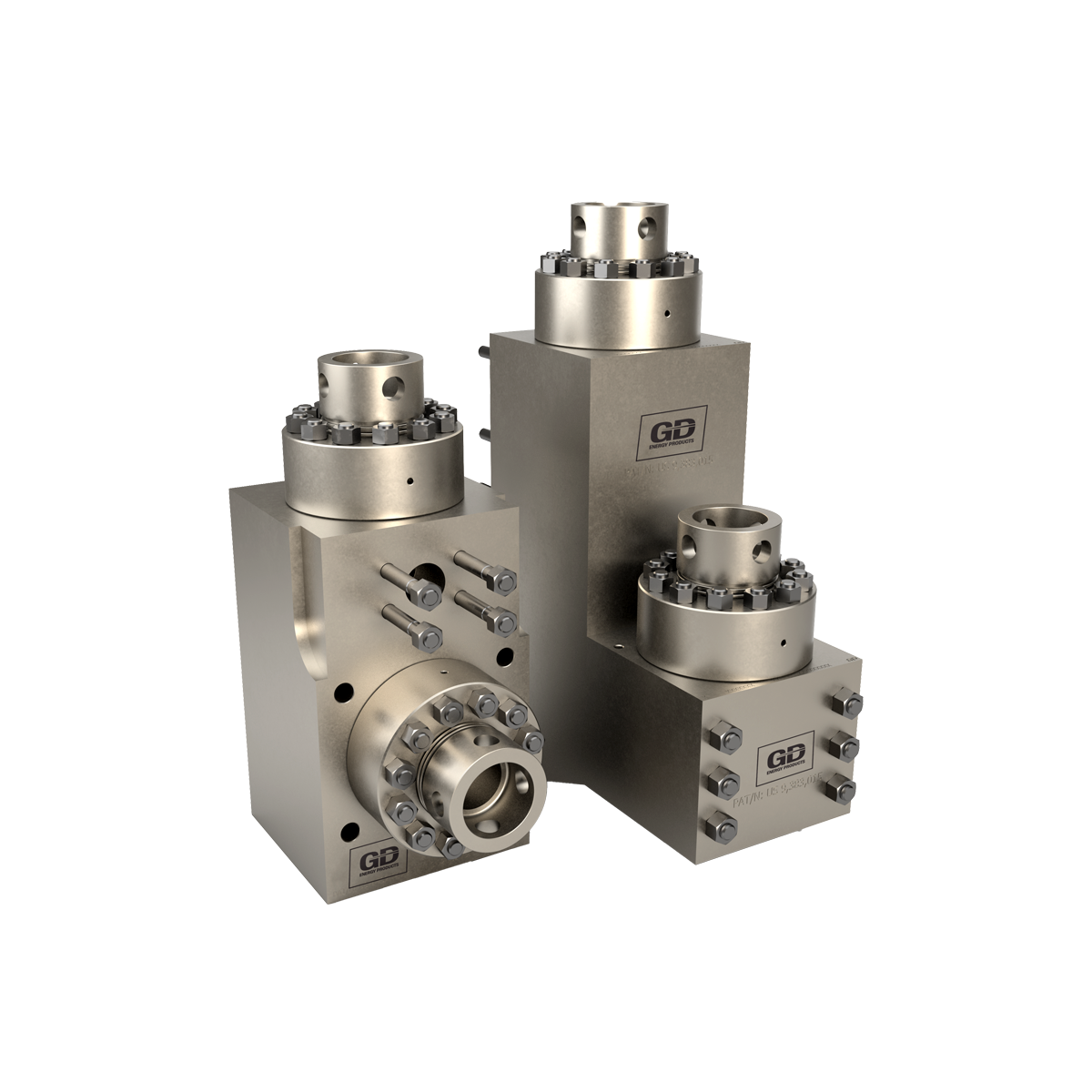
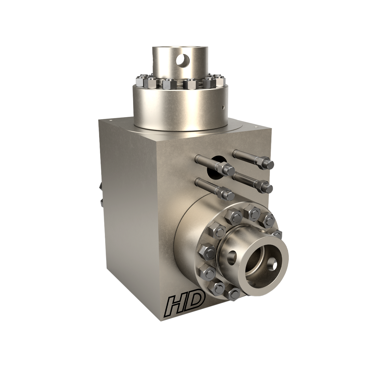
Designed to circulate drilling fluid under high-pressure up to 7500 PSI towards the drill string and backup the annulus, Mud pumps are workhorses that are crucial in drilling rigs. We, at Shalepumps have consistently aided oil and gas exploration with the most rugged and reliable mud pumps. One of the two distinct ends is mud pump fluid end modules, which plays an important role in the function of the pumps. We take a good look at the overall working of the mud pumps.
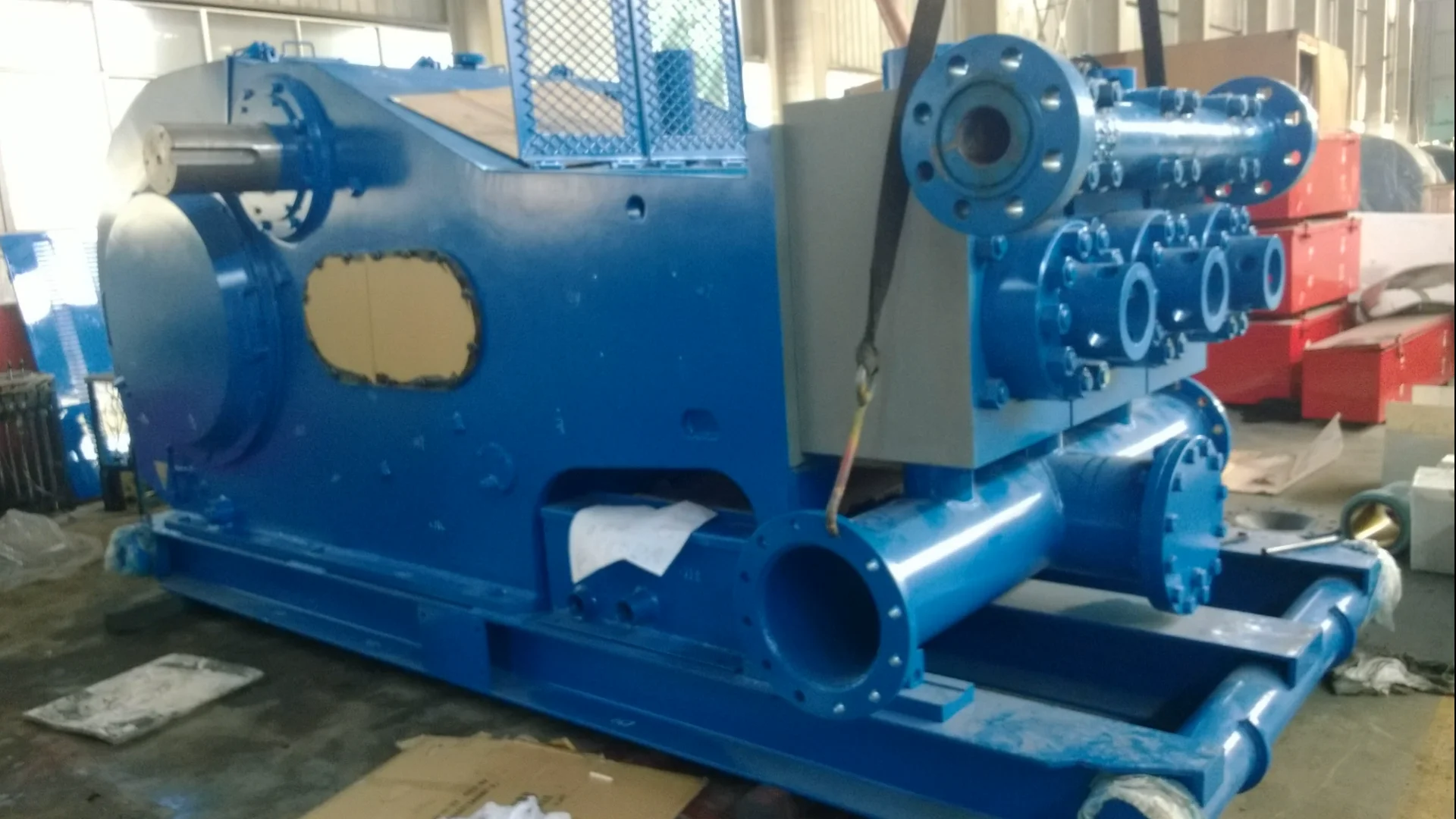
Operational parameters of displacement and pressure – The displacement is calculated on the basis of the diameter of the borehole, and the pressure mainly depends on the depth of the borehole. Deeper boreholes translate into higher resistance and higher pressure. The pump or the power end incorporates adjustable mechanisms that to adjust the pump displacement. The gearbox or hydraulic motor helps in adjusting the speed to meet requirements. At Shalepumps, we take great pride in the fact that the adjustable mechanism we put into the mud pumps offer greater flexibility in quickly adjusting the displacement.
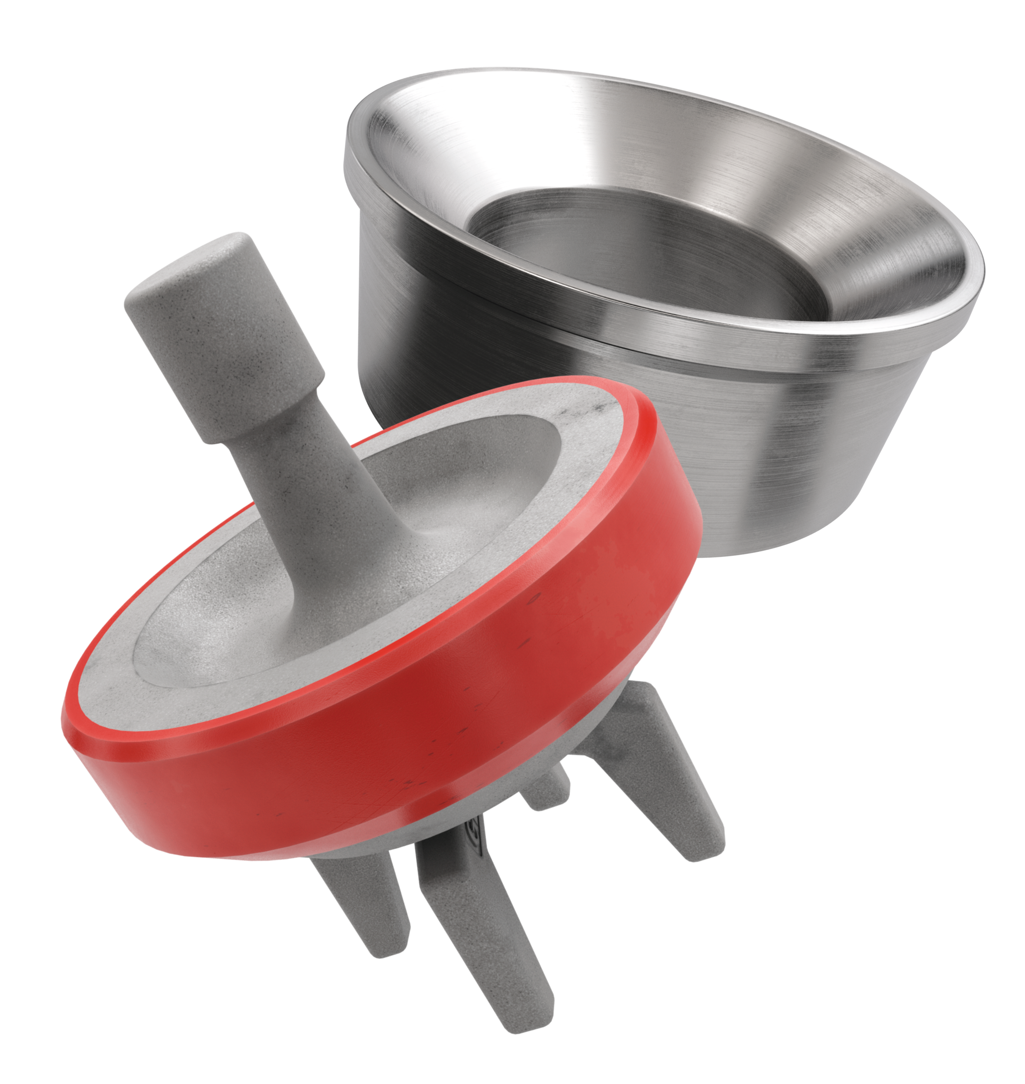
Double acting reciprocating pumps – Inside a mud pump, pistons operate in cylinders to produce pressure. This pressure is used to suck mud and the suction valve is closed and moves to the left. When the pressure in the pipeline increases, the valve is forced open, and as a consequence, mud gets released. This, in a nutshell is the reciprocating action. The mud pump fluid end modules work in perfect unison and synchronization with the power end to produce harmonious reciprocating action and result.
Mud pumps comprise hydraulics such as hydraulic inlet, cylinders, outlet valve, cooling unit, pistons, pneumatic compressor, safety etc. The pump mechanics include casing, reduction, gear, slide crank mechanism, transmission shaft, drive pulley etc. At Shalepumps, each component is tested and rated to function with great efficiency, with longer runs in the most demanding conditions. The mud pumps that we manufacture at Shalepumps make good use of the suction and pulsation dampeners to keep vibration levels low. With lesser vibrations operations are unhindered by frequent maintenance or repairs.
Electronic Pump Stroke Counters are a vital part to any drilling rig operation. When a mud pump is in operation, the driller must know how much mud is flowing down hole in order to keep the operation running at peak efficiency. Pump stroke counters assist the driller by measuring the mud pump’s strokes per minute and total strokes. So, how does a pump stroke counter tally the mud pump’s strokes
Electronic Pump Stroke Counters are a vital part to any drilling rig operation. When a mud pump is in operation, the driller must know how much mud is flowing down hole in order to keep the operation running at peak efficiency. Pump stroke counters assist the driller by measuring the mud pump’s strokes per minute and total strokes. So, how does a pump stroke counter tally the mud pump’s strokes, and why it is important? In order to understand that, you’ll need to know some basic information about mud pumps.
Knowing how a mud pump functions is important in understanding the role a pump stroke counter plays in rig operations. Mud pumps act as the heart of the drilling rig, similar to how our heart works. Just as our heart circulates blood throughout our bodies, a mud pump circulates essential drilling mud down the hole and back up to the surface. Mud tanks house drilling mud, and a mud pump draws the fluid from the mud pump. A piston draws mud in on the backstroke through the open intake valve and pushes mud through the discharge valve and sends it towards the rig. By circulating fluid, the mud pump ensures that the drill bit is cool and lubricated and that cuttings are flushed from the hole. The two main kinds of pumps used are duplex and triplex pumps, where the duplex pump has two pistons and the triplex pump has three. Whether the rig is using a duplex or triplex pump, it is important to know how many strokes per second the pistons are moving. The driller monitors strokes per minute to determine how much costly, yet essential, mud is being pumped into the system with the use of a mud pump stroke counter system. Now, that you know about mud pumps, you’ll need to know what’s in a stroke counter system.
Stroke Counter — The stroke counter stainless steel box is mounted on the driller’s console and is either square or rectangular in shape, depending on the number of pumps it is monitoring. Stroke counters will show strokes per minute and total strokes, and when a particular mud pump is operating the strokes/minute and total strokes will be displayed. Power is supplied by a 3.6 volt lithium battery, and the counter contains a crystal-controlled real time clock with 100 parts per million accuracy or better. Each counter is mounted to the console with 1/4” stainless steel hex head bolts, lock washers and nuts.
Micro Limit Switch — The micro switch is connected to a c clamp near the mud pump piston. The micro switch stainless steel rod (sometimes called a whisker) sticks out in the piston housing near the piston. As the piston passes the rod, it moves the rod and the switch sends an electronic signal back to the counter. The counter increases by one each time the piston moves the rod, counting the mud pump’s strokes. The switch’s signal is then transmitted to the stroke counter. These micro switches are built to stand up to demanding outdoor conditions. They can withstand shock, equipment vibration, extreme temperatures, water and dust.
Cable and Junction Box – A cable is connected to the back of the pump stroke counter and then to the junction box. From the junction box, the cables travel to the limit switches.
Pump Stroke Counters are like a blood pressure machine. Each time our heart pumps, a blood pressure machine reads our systolic and diastolic blood pressure by way of our pulse. A mud pump stroke counter functions in much the same way. Just as a blood pressure machine detects our pulse so too does a limit switch rod detect the movement of the piston. When the stainless steel rod is moved, the micro limit switch detects the movement. The signal is sensed as a contact closure, and it is transmitted to the stroke counter where the contact closure is converted to a logic pulse. The pulse feeds two separate circuits. The total strokes circuit reads and displays the closures one at a time, totaling them up to reveal the total strokes in the LED window. The second pulse is sent along a separate circuit which is a rate circuit. This rate circuit will average the closures against the real time clock. The result is displayed as the total strokes per minute.
Pump stroke counters are essential to drilling rig operations because they measure the efficiency of mud pumps. Knowing strokes per minute and total strokes of the pistons helps the driller to determine if the correct amount of mud is going down hole. Having this information aids in running a drilling rig at peak efficiency, assists in extending drill bit life, and avoids costly overuse of drilling rig mud. Unsure which pump stroke counter is right for your application? Give our friendly, knowledgeable staff a call or email. We’ll keep you turning right.
The drilling industry has roots dating back to the Han Dynasty in China. Improvements in rig power and equipment design have allowed for many advances in the way crude oil and natural gas are extracted from the ground. Diesel/electric oil drilling rigs can now drill wells more than 4 miles in depth. Drilling fluid, also called drilling mud, is used to help transfer the dirt or drill cuttings from the action of the drilling bit back to the surface for disposal. Drill cuttings can vary in shape and size depending on the formation or design of the drill bit used in the process.
Watch the video below to see how the EDDY Pump outperforms traditional pumps when it comes to high solids and high viscosity materials commonly found on oil rigs.
The fluid is charged into high-pressure mud pumps which pump the drilling mud down the drill string and out through the bit nozzles cleaning the hole and lubricating the drill bit so the bit can cut efficiently through the formation. The bit is cooled by the fluid and moves up the space between the pipe and the hole which is called the annulus. The fluid imparts a thin, tough layer on the inside of the hole to protect against fluid loss which can cause differential sticking.
The fluid rises through the blowout preventers and down the flowline to the shale shakers. Shale shakers are equipped with fine screens that separate drill cutting particles as fine as 50-74 microns. Table salt is around 100 microns, so these are fine cuttings that are deposited into the half-round or cuttings catch tank. The drilling fluid is further cleaned with the hydro-cyclones and centrifuges and is pumped back to the mixing area of the mud tanks where the process repeats.
The drill cuttings contain a layer of drilling fluid on the surface of the cuttings. As the size of the drill cuttings gets smaller the surface area expands exponentially which can cause rheological property problems with the fluid. The fluid will dehydrate and may become too thick or viscous to pump so solids control and dilution are important to the entire drilling process.
One of the most expensive and troubling issues with drilling operations is the handling, processing, and circulation of drilling mud along with disposing of the unwanted drill cuttings. The drilling cuttings deposited in the half round tank and are typically removed with an excavator that must move the contents of the waste bin or roll-off box. The excavators are usually rented for this duty and the equipment charges can range from $200-300/day. Add in the cost for the day and night manpower and the real cost for a single excavator can be as much as $1800/day.
Offshore drilling rigs follow a similar process in which the mud is loaded into empty drums and held on the oil platform. When a certain number of filled drums is met, the drums are then loaded onto barges or vessels which take the drilling mud to the shore to unload and dispose of.
Oil field drilling operations produce a tremendous volume of drill cuttings that need both removal and management. In most cases, the site managers also need to separate the cuttings from the drilling fluids so they can reuse the fluids. Storing the cuttings provides a free source of stable fill material for finished wells, while other companies choose to send them off to specialty landfills. Regardless of the final destination or use for the cuttings, drilling and dredging operations must have the right high solids slurry pumps to move them for transport, storage, or on-site processing. Exploring the differences in the various drilling fluids, cutting complications, and processing options will reveal why the EDDY Pump is the best fit for the job.
The Eddy Pump is designed to move slurry with solid content as high as 70-80 % depending on the material. This is an ideal application for pumping drill cuttings. Drill cuttings from the primary shakers are typically 50% solids and 50% liquids. The Eddy Pump moves these fluids efficiently and because of the large volute chamber and the design of the geometric rotor, there is very little wear on the pump, ensuring long life and greatly reduced maintenance cost for the lifetime of the pump.
plumbed to sweep the bottom of the collection tank and the pump is recessed into a sump allowing for a relatively clean tank when the solids are removed. The Eddy Pump is sized to load a roll-off box in 10-12 minutes. The benefit is cuttings handling is quicker, easier, safer, and allows for pre-planning loading where the labor of the solids control technician is not monopolized by loading cuttings. Here, in the below image, we’re loading 4 waste roll-off bins which will allow the safe removal of cuttings without fear of the half-round catch tank running over.
Mud cleaning systems such as mud shaker pumps and bentonite slurry pumps move the material over screens and through dryers and centrifuges to retrieve even the finest bits of stone and silt. However, the pump operators must still get the raw slurry to the drill cuttings treatment area with a power main pump. Slurry pumps designed around the power of an Eddy current offer the best performance for transferring cuttings throughout a treatment system.
Options vary depending on whether the company plans to handle drill cuttings treatment on-site or transport the materials to a remote landfill or processing facility. If the plan is to deposit the cuttings in a landfill or a long-term storage container, it’s best to invest in a pump capable of depositing the material directly into transport vehicles. Most dredging operations rely on multiple expensive vacuum trucks, secondary pumps, and extra pieces of equipment.
Using an EDDY Pump will allow a project to eliminate the need for excavators/operators to load drill cuttings, substantially lowering both labor and heavy equipment costs. The EDDY Pump also allows a company to eliminate vacuum trucks once used for cleaning the mud system for displacing fluids. Since the pump transfers muds of all types at constant pressure and velocity throughout a system of practically any size, there’s little need for extra equipment for manual transfer or clean up on the dredge site.
The EDDY Pump can fill up a truck in only 10 minutes (compared to an hour) by using a mechanical means such as an excavator. For this reason, most companies can afford one piece of equipment that can replace half a dozen other units.
This application for the Eddy Pump has the potential to revolutionize the drilling industry. Moving the excavator out of the “back yard” (the area behind the rig from the living quarters) will make cuttings handling a breeze. Trucking can be easier scheduled during daylight hours saving on overtime and incidences of fatigued driving. Rig-site forklifts can move the roll-off boxes out of the staging area and into the pump loading area. The operator can save money on excavators rental, damages, and keep the technician operating the solids control equipment.
The EDDY Pump is ideal for drilling mud pump applications and can be connected directly onto the drilling rigs to pump the drilling mud at distances over a mile for disposal. This eliminates the need for costly vacuum trucks and also the manpower needed to mechanically move the drilling mud. The reasons why the EDDY Pump is capable of moving the drilling mud is due to the hydrodynamic principle that the pump creates, which is similar to the EDDY current of a tornado. This tornado motion allows for the higher viscosity and specific gravity pumping ability. This along with the large tolerance between the volute and the rotor allows for large objects like rock cuttings to pass through the pump without obstruction. The large tolerance of the EDDY Pump also enables the pump to last many times longer than centrifugal pumps without the need for extended downtime or replacement parts. The EDDY Pump is the lowest total life cycle pump on the market.

Centerline Manufacturing has been involved in the design, manufacture and production of drilling equipment and tooling for the water well industry. I have had the pleasure of knowing and working with Cory Miller of Centerline Manufacturing over the past 15 years. As the Senior Design Engineer for Ingersoll-Rand’s Deephole Drilling Business Unit, I had the distinct pleasure to work with Cory and integrate his Centerline Mud Pump into our drilling rig platforms. I am recommending Cory for this award and recognition because after decades in this business, I have not seen such an innovative design become a reality and commercialized such as the Centerline Mud Pump.
The true innovation is providing well drillers a size and weight solution for their mud pump requirements. Centerline Mud Pumps integrate into both existing and new drilling rigs. Regardless of drill rig manufacture and hydraulic system design, Centerline provides mud pump integration on hundreds of customer’s drilling rigs. Both Mono Cylinder and Duplex Cylinder Pumps can fit nicely on the deck, across the frame or even under deck mounting configurations. This would not be possible with conventional mud pump designs.
The design features of the Centerline Mud Pump include a matched displacement ratio between the mud pump cylinder and the hydraulic drive cylinder. This is critical to the constant and smooth transition of movement back and forth. It provides a steady discharge flow of mud.
What I dignifies Cory Miller and points to his character? It is how Centerline stuck with their original design through all of the typical trials and tribulations that come with a new product integration. The first several years were challenging. Cory found out that even the best quality hydraulic cylinders and valves and seals were not good enough quality. He then set off on an endeavor to bring everything in house. He began manufacturing all of his own components including hydraulic valves. This gave him complete control over the quality of very component that goes into the Centerline Mud Pump and the finished product.
By the late 90’s, Ingersoll-Rand had tried several times to develop a hydraulic driven mud pump. The goal was to create a mud pump that would last an acceptable life and duty cycle for well drilling contractors. With all of our resources and design wisdom, we were unable to solve this problem. Not only did Cory Miller provide a solution, thus saving the size and weight of a typical gear driven mud pump, he also provided a new offering of a mono cylinder mud pump. This double acting piston pump provided as much mud flow and pressure as a standard 5 X 6 duplex pump. It also came with an incredible size and weight savings.
The second generation design for the Centerline Mud Pump is coming out later in 2018. It will be a true game changer for this industry. It also will open up the application into many other industries that require a heavier duty cycle for a piston pump application.
Whether onshore or offshore, well drilling sites rely on a multitude of systems to successfully perform the drilling operation. The mud pump is a key component tasked with circulating drilling fluid under high pressure downhole. The mud pump can be divided into two key sections: the power end or crosshead and the fluid end. Proper alignment of the pump’s crosshead to the fluid end liner is necessary to maximizing piston and liner life. Misalignment contributes to
accelerated wear on both the piston and the liner, and replacing these components requires downtime of the pump. Traditional methods of inspecting alignment range from using uncalibrated wooden rods, Faro Arms and micrometers to check the vertical and horizontal alignment of the piston rod OD to the piston liner ID. These are time consuming and cumbersome techniques that are ultimately not well suited to troubleshoot and solve alignment issues.
A “Mud Pump Laser Alignment Kit” enables you to measure where the piston will run through the liner at various positions along the pump’s stroke. It will also project a laser centerline from the fluid end back towards the rear power end of the pump that can be used to determine how much shimming is required to correct any alignment issues. The kit can include either a 2-Axis receiver or a 4-Axis which accepts the laser beam and documents where it falls on the active surface of the receiver. The 4-Axis receiver can decrease alignment time by as much as 50% as it will measure angularity as well as X and Y while the 2-Axis does not and will need multiple measurement locations to get the same information. In addition, the alignment system is a non-intrusive service requiring the removal of only the piston rod which allows for much quicker service and less down time on the pump. As the mud pumps in question are located globally both on and offshore, having a small, portable system is another great advantage. Our recommendation would be Pinpoint laser System’s “Mud Pump Alignment Kit”. They are being used by many of the leading repair service companies and have been their main alignment tool for over 15 years. Manufacturers are also utilizing these for new pump set-up.

Mud Pump Pulsation Dampener is usually installed on the discharge line to reduce the fluctuation of pressure and displacement of the drilling mud pump.
Mud Pump Pulsation Dampener is a pneumatic device built into the outflow line of each UUD pump to dampen the pressure fluctuations resulting from the action of the pump. Although presented as a surge tank, this device is really a device that can be tuned to greatly diminish the output pulsations transmitted downstream from the mud pump. Unfortunately, the effectiveness of the pulsation dampener is a function of both output pump pressure and frequency of the pump pulsations.

Kill manifold consists of check valves, gate valves, line pipes, pressure gauges. In case of increase in well head pressure, the kill manifold can provide a means of pumping heavy drilling fluid into the well to balance bottom hole pressure so that well kick and blowout can be prevented. In this case, by using blow down lines connected to the kill manifold, the increasing well head pressure also can be released directly for bottom hole pressure release. or water and extinguishing agent can be injected into the well by means of kill manifold.

Drilling in the North Sea is confronted with an ever more challenging pressure-management issue because of narrow geopressure windows in depleted reservoirs. Further, the occurrence of packoffs can cause serious damage to the formation and contribute to nonproductive time. To address these problems, automation of mud-pump management has been developed over the last 4 years to minimize the chance of fracturing the formation while starting the mud pumps or circulating. To account for abnormal flow restrictions in the annulus, automatic actions are also an integral part of the mud-pump automation described in this paper.
Since the downhole conditions are continuously changing (e.g., depth, temperature, flow-rate, gel time, cuttings proportion), the necessary safeguards to operate the mud pumps need to be updated constantly. Advanced transient temperature and hydraulic models are used to estimate, in real-time, the downhole situation. On the basis of the current context, evaluations of maximum pump rates and acceptable flow accelerations are performed and sent to the mud-pump control system to be used as an envelope of protection. Furthermore, to assist the driller during connections, the pump-startup procedure has been semiautomated to decrease connection time. Finally, an automatically triggered pump-shutdown procedure is also available to minimize the consequences of a packoff on formation fracturing.
A first version of the system has been tested during the drilling of one well in 2008 in the North Sea. Based on the initial experience, a revised version has been used during the drilling of three wells drilled on the Norwegian continental shelf in 2009. The feedback from the drillers involved in the testing has been used to improve the user friendliness of the system. The automation of the mud-pump management has been well accepted by the drilling crews. However, the testing has shown that additional instrumentation at the rigsite is necessary before such automation can be rolled out safely.

When it comes to the process of Mud pump repair, our expertise is second to none. Unlike smaller machine shops, We are pump repair specialists with expertise in repairing and rebuilding Mud pumps. We offer several level of rebuild options in order to make your Mud pump repair is as efficient and as economical as possible. We can manufacture many of the required components in-house for a Mud pump repair and or Mud pump rebuild as well.
You can trust the knowledge and expertise of your Mud pump repair in our hands. We have decades of qualified experience in the troubleshooting of your Mud pump repair, view our
We know the ins and outs of what made the Mud gearbox to fail, from the erosion that happens, to wear and tear of seals, it’s a common thing. That’s why trusting your Mud pump repair in our shop can only bring life to your Mud.
It’s not uncommon for other machine shops just trying to figure it out. Not here. We don’t have to figure out what happened to your Mud pump, again we have years and years of experience with Mud pumps and the Mud pump repair process. Although sometimes the Mud pump rebuild is a little bit different, we can ensure you that your Mud pump will be restored. It’s not uncommon for the Mud pump repair to suddenly turn into a process of rebuilding the Mud pump due to a further analysis of the breakdown in our shop.
We don’t take a first option of a rebuild due to it’s expense, because sometimes that can become a re-manufacturing process especially if the pump is very aged, but in the end, if a rebuild is needed for any type of re-manufacturing needs, you can count on MER to get the job done, that’s why we have a full facility dedicated to re-manufacturing these types of equipment to ensure the proper repair of your Mud pump. Nevertheless, we will let you know in what category it falls in before we even start the process of the Mud pump repair or the Mud pump rebuild.


 8613371530291