
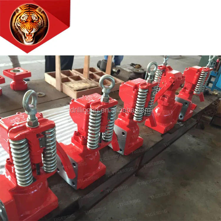
mud pump pressure relief valves free sample

30 pressure relief valve for mud pump products are offered for sale by suppliers on Alibaba.com, of which mud pump accounts for 36%, pumps accounts for 23%.
A wide variety of pressure relief valve for mud pump options are available to you, You can also choose from new, pressure relief valve for mud pump,as well as from energy & mining, construction works , and machinery repair shops pressure relief valve for mud pump,and whether pressure relief valve for mud pump is 1.5 years, or 3 months.

For 50 years, Giant Pumps has offered the most dependable positive displacement high-pressure triplex pumps available. Designed and built to the highest quality standards, customers count on Giant Pumps products to keep their equipment running. Every design detail of Giant Pumps products is optimized for long-life and reliable performance, making Giant Pumps the most trusted name in high-pressure pumps and systems.

The invention related to drilling fluid or “mud” systems; to relief valves for such systems; and to apparatus, systems and methods for relieving fluid pressure in pressurized devices or systems.
In certain typical wellbore drilling situations using a drilling rig, drilling fluid or “mud” is pumped by a pumping system with one or more “mud” pumps (e.g. some systems have a triplex mud pump). The mud pump system delivers a large volume of mud flow under pressure for operations of the drilling rig. The mud is delivered to the drill stem to flow down the string of drill pipe and out through the drill bit appended to the lower end of the drill stem. It flows through the drill bit. The flow of mud cools the drill bit and reduces the temperature so that it lasts longer. Also, in certain situations, the mud flow is jetted out through a set of openings in the drill bit so that the mud hydraulically washes away the face of the well borehole if it is formed of soft materials. In addition, it washes away debris, rock chips and cuttings which are generated as the drill bit advances. Then, the mud flow returns to the surface in an annular space on the outside of the drill stem and on the interior of the open hole formed by the drilling process. While portions of the borehole may be cased from the surface, is of sufficient velocity that the mud is returned to the surface so that debris, chips and cuttings which are heavier than the mud are moved to the surface. This requires a substantial flow velocity. The cooling necessary also requires a substantial velocity. A relatively high volume of mud is needed to achieve these flow velocities. Typical mud pump systems can deliver 500 to 1,000 gallons per minute through the drill stem. The flow of mud must be delivered under control. The mud pump system can be required to deliver mud flow at 1,000 psi and higher. The wellhead pressures at the pump must be much higher if there is substantial flow pressure resistance along the flow path. The pump therefore is often operated at a very high pressure. The drill stem in a deep well is an impediment to flow, thereby resulting in higher back pressures. The impediment to flow is overcome by applying greater pressures at the surface. In this regard, the mud pump system can typically be operated at pressures as high as 5,000 psi output. Because of the great variety of circumstances in which the drilling rig may be used, the output pressure of the mud pump may vary widely. In one aspect, the mud pump output pressure varies with the change in pump speed. Mud pumps can operate with pressure peaks that can be excursions as great as 200 or 300 psi on top of the prevailing baseline pressure. Thus mud pump output pressure can vary significantly.
The prior art discloses a variety of mud systems, relief valves and regulators, and systems to control and stabilize the pressure downstream of mud pump systems; see, for example, and not by way of limitation, U.S. Pat. Nos. 5,063,776; 5,616,009; 5,975,129; 7,055,623; 5,715,861; 4,638,978; and in U.S. application Ser. No. 11/098,166 filed Apr. 4, 2005 (co-owned with the present invention), all incorporated fully herein for all purposes. In many prior art systems, a mud pump output manifold is input to a pressure relief valve which is operated so that the output pressure is controlled to a desired level, thus allowing a mud pump system to operate with a controlled pressure level to insure that the pressure experienced down hole at the drill bit and in the formations penetrated by the drill bit is regulated and to protect the mud pump system itself.
Various operations involve the use of pressurized systems and/or devices. For example, many different components used in the petroleum drilling and production industries, such as fluid pumps and mud pumps, are used in pressurized systems and subject to potentially significant internal fluid pressures. It is often desirable or necessary to relieve these systems and devices from excessive pressure to prevent equipment damage and failure, personal injury or for other reasons. To assist in relieving undesirable fluid pressure in pressurized systems and devices, pressure relief technology is commonly used.
Currently available versions of pressure relief valves, systems and methods have various disadvantages. For example, many pressure relief valves wear and fail quickly due to high pressure fluid passing therethrough. For another example, various versions of pressure relief valves are large and bulky and require extensive space for operation. For still another example, many pressure relief valves are difficult to disassemble for servicing and maintenance. For an even further example, some pressure relief valves throttle between open and closed positions during operation, which is undesirable in many applications. For still another example, some pressure relief valves are purely mechanical in operation, which may contribute to inaccurate valve operation and overall poor or erratic performance. There are yet other potential disadvantages of presently available pressure relief valves, systems and methods. It should be understood, however, that each embodiment of the present invention and each claim of this patent does not necessarily address or solve every, or any particular, disadvantage of the existing technology.
Thus, there remains a need for pressure relief valve assemblies, systems and methods having one or more of the following attributes, capabilities or features: may be easily disassembled and reassembled; is easy to inspect and service, adjust and/or repair in the field; allows for the repair and replacement of internal valve components without removing the valve body from the line or equipment to which it is attached; has reduced likelihood of damage to internal valve components when discharging fluids; is not difficult to manufacture; includes a valve that is easily opened to allow access for inspection or removal of internal components; includes a valve having an angle-body configuration and/or a fluid flow path with approximately a ninety degree turn; includes a valve having a “flow-to-close” and/or a “fail-to-open” arrangement; includes a valve that opens rapidly and resets easily; includes a snap or pop acting valve; includes a valve having increased longevity; includes a valve that does not throttle between open and closed positions so that when the fluid pressure in the pressurized device is too high, the valve stays fully open until closed; includes a valve actuator that is integral to the valve; includes a reciprocating valve actuator stem or piston that does not protrude from the valve assembly; includes a valve actuator that is electronically controllable; includes an actuator piston engaged with and moveable on the same axis as the valve piston; includes an actuator piston actuated based upon the actual measured pressure of fluid in the pressurized device or system; includes a solenoid valve useful to assist in controlling movement of an actuator piston; includes a valve piston and/or actuator piston that is mechanically-biased in one direction; includes a valve piston and/or actuator piston that is controllably movable in one direction by fluid pressure; includes a valve piston and/or actuator piston that is internally sealed without metal seating; or any combination thereof. BRIEF SUMMARY OF THE PRESENT INVENTION
The present invention, in certain embodiments, discloses pressure relief valve assemblies useful for relieving fluid pressure in a pressurized device (e.g., but not limited to, mud pump systems with at least one mud pump), the pressure relief valve assemblies having: a valve body with an inlet passageway in fluid communication with an outlet passageway; a valve member within the valve body for selectively controlling fluid flow from the inlet passageway to the outlet passageway, the valve member having a first end and a second end, the outlet passageway having an entrance end and an exit end; the first end of the valve member movable into the outlet passageway to prevent fluid flow from the inlet passageway through the outlet passageway; a wear member around a portion of the entrance end of the outlet passageway; the wear member having an interior surface; the valve member movable within and sealingly contacting the interior surface of the wear member; the outlet passageway having a length, the wear member extending into the outlet passageway a distance less than the length of the outlet passageway; the valve body having an interiorly threaded portion at the entrance of the outlet passageway; the wear member having an exteriorly threaded portion; and the wear member releasably secured to the valve body by threaded engagement of the wear member"s exteriorly threaded portion with the valve body"s interiorly threaded portion.
Various embodiments of the present invention involve a pressure relief valve assembly useful for relieving fluid pressure in a pressurized device. The pressure relief valve assembly, in certain aspects, includes an angle-body valve having a valve piston disposed therein and being movable between at least one closed position and at least one open position. The closed position of the valve piston prevents fluid flow through the valve from the pressurized device and the open position allows fluid flow through the valve from the pressurized device.
At least one electronic pressure measuring device is separate from and associated with certain embodiments of the remotely-operated directional control valve and monitors pressure within the pressurized device. The position of the remotely-operated directional control valve is varied based upon power supplied to the control valve that is based upon at least one reading taken by the electronic pressure measuring device.
In some embodiments, a pressure relief valve assembly useful for relieving fluid pressure in a pressurized device includes an unintelligent angle-body valve having a flow-to-close arrangement. The valve includes a valve piston capable of moving between open and closed positions. The valve piston in the open position allows venting of fluid from the pressurized device through the valve. Movement of the valve piston into an open position does not depend upon internal fluid pressure within the unintelligent angle-body valve. At least one electronic pressure measuring device is capable of monitoring pressure within the pressurized device. An electronic controller is capable of causing the opening and closing of the valve piston based upon pressure readings of the electronic pressure measuring device.
Accordingly, the present invention includes features and advantages which are believed to enable it to advance pressure relief valve technology. Characteristics and advantages of the present invention described above and additional features and benefits will be readily apparent to those skilled in the art upon consideration of the following detailed description of preferred embodiments and referring to the accompanying drawings.
Referring to FIG. 1, a system S according to the present invention includes a mud system M with mud pits 28 for containing and storing drilling fluid; mud pumps 16 for pumping the drilling fluid to drillstring 18 and back to the mud pits 28; and a relief valve 8 according to the present invention for relieving pressure in the system. The drilling fluid or “mud” flows down the drill string 18 and then up in an annulus 20 between casing 22 and the drill string 18 to a bell nipple 24. The mud then flows in a return line 26 to the mud pits 18.
Initially mud flows into the valve 8 through a line 21 that is in communication with the line 19. A pressure sensor 23 senses a signal indicative of the pressure in the line 19, via the line 21, to a control system 14 which controls operation of the valve 8 and controls an air supply 12 which provides air under pressure to maintain the valve 8 closed until a pre-selected mud pressure is exceeded. When the mud pressure exceeds the pre-selected pressure, the valve 10 opens and the mud that was previously flowing to the drill stem 18 flows through the inlet 13 of the valve 8 and exits through an outlet 15 into an exit line 17. When pressure in the line 19 again falls below the pre-selected pressure, the control system 14 signals the air supply 12 to close the valve 8 (as will be described in more detail for certain embodiments described below).
FIG. 2 shows schematically the mud flow path for the system M. As shown in FIG. 2, the system M (like numerals indicate like parts) includes a degasser 25 which reduces the gas content of the mud. In certain aspects, the control system (“CONTROLLER”) includes an automatic reset function and also permits manual resetting (“ReSet,” FIG. 2), e.g. to re-close the valve after it has relieved pressure; and/or the possibility of two settings (“Hi,” “Low,” FIG. 2) corresponding to two different pressure setpoints (e.g. a high setting, e.g. 7500 psi, at which the valve opens for relief and a low setting, e.g. below 400 psi). The valve is operable by manually pressing an “Operate” button. The controller can be a computerized system and/or PLC appropriately programmed.
Referring now to FIGS. 3A-3C, a relief valve 100 (one embodiment of the relief valve 8, FIG. 1) includes a valve 120 and an actuator 160. In the embodiment shown, the valve 120 is an angle-body, two-way valve that includes a valve body 126 having intersecting first and second passageways 130, 140. The first passageway 130 is in fluid communication with a pressurized device (not shown) (e.g. a mud pump or pumps) and allows fluid flow (arrow 131) into the valve body 126 from the pressurized device. The second passageway 140 extends to an exit port 144, allowing the exhaust (arrow 146) of fluid from the valve body 126. In an “angle-body” valve, the axis of the first passageway 130 is not concentric or coaxial with, but is approximately in the same plane as, the axis of the second passageway 140. Nuts 132 aare used on valve body studs 132 b; and nuts 142 aare used on valve body studs 142 b.
The actuator piston 174 may be actuated in any desired manner. In the embodiment shown in FIG. 3A, the actuator piston 174 is single acting, being fluid-powered in one direction (e.g. by pneumatic or hydraulic pressure) and mechanically-biased in the opposite direction. In one aspect when the pressurized device is a mud pump or pumps, the power fluid is air, e.g. air supplied by a rig air supply. For example, air or pneumatic pressure may be provided from an external source (not shown) into an outer portion 172 of the central cavity 170 of the actuator housing 164 to act upon an outer side 178 of the actuator piston 174 and move and hold the actuator piston 174 in an “extended” position and the valve piston 148 in a closed position (e.g. FIG. 3A). In the illustrated embodiment, in one normal operating state of the valve assembly 100 has the actuator piston 174 in an extended position and the valve piston 148 in a closed position.
The mechanical-biasing force on the actuator piston 174 (and effectively on the valve piston 148), when included, may be provided in any suitable manner. For example, one or more spring element or spring-like devices may be used to provide the sufficient biasing forces on the actuator piston 174 and move and hold the actuator piston 174 in a retracted position and the valve piston 148 in an open position, regardless of the system pressure or fluid pressure in the valve assembly 100.
In another independent aspect of the invention, the actuator 160 may be controlled to move the valve piston 148 between open and closed positions in any desired manner. For example, referring to FIG. 3A, the actuator 160 may be controlled based upon the fluid pressure within, or coming from, the pressurized device (not shown), referred to herein and throughout this patent as the “relevant pressure.” Such a control scheme is referred to herein and throughout this patent as a “pressure-based” system. For example, when the valve assembly 100 of FIG. 3A is used with a fluid pump, the relevant pressure may be the upstream pressure of fluid flow into the first passageway 130 of the valve body 126 from the fluid pump. When the relevant pressure is at an acceptable or desirable value (or range), the actuator 160 retains the valve piston 148 in a closed position, not relieving pressure from the fluid pump. If the relevant pressure increases to a certain level or range, the actuator 160 is triggered to move the valve piston 148 to an open position, allowing fluid pressure relief for the fluid pump. After a certain period or, alternately, when the relevant pressure returns to a certain level or range, the actuator 160 of this example is adjusted to allow the valve piston 148 to move back to a closed position, and so on.
Any suitable components and techniques may be used in a pressure-based system. For example, a directional control valve may be used to control fluid power acting upon the actuator piston to allow it to move from an extended position to a retracted position. For example, referring to FIG. 3A, the directional control valve is a three-way, two position solenoid valve (not shown) used to control pneumatic or other fluid pressure in the outer portion 172 of the central cavity 170 of the actuator housing 164. The exemplary solenoid valve is connected with the actuator end cap 182 and actuated based upon the relevant pressure of the pressurize device (not shown). In the embodiment shown, the solenoid valve is maintained in a fluid-to-cylinder/exhaust-blocked position that allows pressurized fluid to the outer portion 172 of the outer cavity 170 through at least one port 166 to act upon the outer side 178 of the actuator piston 174 and move or retain the actuator piston 174 in an extended position. For example, air pressure in the outer portion 172 of the central cavity 170 may, in certain applications, be maintained at approximately 90 psig.
If the relevant pressure reaches a certain value (or range), the solenoid valve is actuated to move to a supply-fluid-blocked/cylinder-exhausted position, blocking or preventing pressurized fluid from acting upon the outer side 178 of the actuator piston 174 and allowing pressurized fluid from the outer portion 172 of the central cavity 170 to be exhausted from the actuator 160. This permits the actuator piston 174 to move into a retracted position, opening the valve piston 148. When the relevant pressure returns to a desired level or range, the solenoid valve is actuated to allow fluid back into the outer portion 172 of the central cavity 170 of the actuator 160. In the embodiment shown, the mechanical forces on the actuator piston 174 are overcome and the actuator piston 174 returns to an extended position, closing the valve piston 148.
In yet another independent aspect of the invention, the actuator 160 may be electronically controlled by an electronic control device or system, if desired, e.g. the “CONTROLLER” of FIG. 2 which may be any suitable control system, computerized system, and/or PLC, on-site or remote. In conjunction with the embodiment of FIG. 3A, a control valve according to the present invention is on-site or remotely-operated by a programmable logic controller (PLC) that receives relevant pressure readings from one or more electronic pressure measuring devices (e.g. “SENSOR,” FIG. 2). For example, the electronic pressure measuring device may be a pressure transducer that accurately measures, detects or reads fluid pressure in the pressurized device or the upstream pressure of fluid within, or proximate to, the first passageway of the valve body. If desired, the electronic pressure measuring device may either continuously or intermittently monitor such pressure. The position of the exemplary remotely-operated directional control valve is varied based upon electrical, mechanical, fluid power or a combination thereof supplied to it based upon at least one reading taken by the electronic pressure measuring device.
In operation of the illustrated embodiment used in conjunction with the valve assembly 100 of FIG. 3A, the PLC is powered by any suitable power supply and receives input indicating the relevant pressure from the electronic pressure measuring device. The PLC compares the received fluid pressure value(s) with one or more pre-programmed set point values or ranges (the “set point”). If the relevant pressure reaches the set point, the PLC closes a relay (not shown), providing electric power to the directional control valve, causing it to function to temporarily block the fluid supply, such as from a rig air source, into the central cavity outer portion and allow the fluid in the outer portion to exhaust out of the actuator through the directional control valve. The actuator piston is then allowed to move into a retracted position, opening the valve piston.
Thereafter, when the PLC detects that the relevant pressure has returned to a desired value/range, or based upon some other criteria, the PLC resets, or opens, the relay, reducing or eliminating power to the directional control valve. This causes the valve to function to allow fluid back into the outer portion of the central cavity, which moves the actuator piston back to an extended position. If desired, multiple set points may be used. In one example, a 0-8,000 p.s.i. pressure relief valve assembly 100 snaps open quickly (with minimal throttling) based upon a signal from a pressure transducer at a degree of accuracy of with 20% (±16 psig) of the set point pressure value. However, the present invention is not limited to such electronic control or the control components and techniques described above.
Referring initially to FIG. 1, an embodiment of a pressure relief valve assembly 10 in accordance with the present invention is shown. The pressure relief valve assembly 10 is capable of relieving fluid pressure in a device or system which is desired to be relieved of pressure (referred to herein and throughout this patent as a “pressurized device”). As used herein and throughout this patent, the term “fluid” means one or more gas, liquid, or a combination thereof, and may, if desired and suitable, also include material or particles, or slurries thereof. The pressurized device may, for example, include a triplex or duplex mud pump that may experience overpressure situations. In various embodiments, the valve assemblies of the present invention relieves such overpressure situations. However, the present invention is not limited to such use with mud pumps.
The present invention, therefore, in some, but not necessarily all embodiments, provides pressure relief valve assemblies useful for relieving fluid pressure in a pressurized device, the assemblies having: a valve body with an inlet passageway in fluid communication with an outlet passageway; a valve member within the valve body for selectively controlling fluid flow from the inlet passageway to the outlet passageway, the valve member having a first end and a second end, the outlet passageway having an entrance end and an exit end; the first end of the valve member movable into the outlet passageway to prevent fluid flow from the inlet passageway through the outlet passageway; a wear member around a portion of the entrance end of the outlet passageway; the wear member having an interior surface, the valve member movable within and sealingly contacting the interior surface of the wear member; the outlet passageway having a length, the wear member extending into the outlet passageway a distance less than the length of the outlet passageway; the valve body having an interiorly threaded portion at the entrance of the outlet passageway; the wear member having an exteriorly threaded portion, and the wear member releasably secured to the valve body by threaded engagement of the wear member"s exteriorly threaded portion with the valve body"s interiorly threaded portion. Such assemblies may have one or some (in any possible combination) of the following: wherein the wear member has a length which is less than half the length of the outlet passageway; an actuator connected to the second end of the valve member for selectively actuating the pressure relief valve assembly; the actuator including an actuator housing with a flange, the flange having bolt holes therethrough, the flange releasably bolted to the valve body; a first cap at the first end of the valve member, and a second cap at the second end of the valve member; a bore through the valve body, the wear member accessible through the bore for installation and removal thereof; a bore through the valve body, the wear member accessible through the bore for installation and removal thereof, the actuator having an actuator housing bolted to the valve body, part of the actuator housing projecting into the bore, the bore accessible when the actuator housing is unbolted from the valve body and the actuator is removed therefrom; a controller for selectively moving the valve member; the controller includes an automatic reset function to automatically close the pressure relief valve assembly following the pressure relief valve assembly acting to relieve pressure in a pressurized device; the controller programmable to reset at one of a plurality of different measured pressures at the inlet passageway; the controller able to reset the pressure relief valve assembly automatically; the pressure relief valve assembly is resettable manually; the fluid pressure is pressure of drilling fluid and the pressurized device includes apparatus for the flow of drilling fluid under pressure; the pressurized device includes at least one mud pump; wherein the wear member is made of INCONEL material; and/or the actuator is initially acted upon by fluid under pressure to maintain the valve member in a valve-closed position.
The present invention, therefore, provides pressure relief valve assemblies useful for relieving fluid pressure in a pressurized device, the assemblies having: a valve body with an inlet passageway in fluid communication with an outlet passageway; a valve member within the valve body for selectively controlling fluid flow from the inlet passageway to the outlet passageway, the valve member having a first end and a second end, the outlet passageway having an entrance end and an exit end; the first end of the valve member movable into the outlet passageway to prevent fluid flow from the inlet passageway through the outlet passageway; a wear member around a portion of the entrance end of the outlet passageway; the wear member having an interior surface, the valve member movable within and sealingly contacting the interior surface of the wear member; the outlet passageway having a length, the wear member extending into the outlet passageway a distance less than the length of the outlet passageway; the valve body having an interiorly threaded portion at the entrance of the outlet passageway; the wear member having an exteriorly threaded portion; the wear member releasably secured to the valve body by threaded engagement of the wear member"s exteriorly threaded portion with the valve body"s interiorly threaded portion; wherein the wear member has a length which is less than half the length of the outlet passageway; an actuator connected to the second end of the valve member for selectively actuating the pressure relief valve assembly; a bore through the valve body; the wear member accessible through the bore for installation and removal thereof; the actuator having an actuator housing bolted to the valve body, part of the actuator housing projecting into the bore; and the bore accessible when the actuator housing is unbolted from the valve body and the actuator is removed therefrom.
The present invention, therefore, provides in at least some embodiments, but not necessarily all, pressure relief valve assemblies useful for relieving fluid pressure in a pressurized device, the pressure relief valve assemblies having: a valve body with an inlet passageway in fluid communication with an outlet passageway; a valve member within the valve body for selectively controlling fluid flow from the inlet passageway to the outlet passageway, the valve member having a first end and a second end, the outlet passageway having an entrance end and an exit end; the first end of the valve member movable into the outlet passageway to prevent fluid flow from the inlet passageway through the outlet passageway; a wear member around a portion of the entrance end of the outlet passageway; an actuator connected to the second end of the valve member for selectively actuating the pressure relief valve assembly; wherein the actuator includes an actuator housing with a part, e.g., but not limited to, a flange; the part having bolt holes therethrough; and the part and therefore the housing releasably bolted to the valve body. Such an assembly may have: fluid pressure which is pressure of drilling fluid, and the pressurized device including apparatus for the flow of drilling fluid under pressure; and/or the pressurized device including at least one mud pump.
In many liquid piping systems, it is vital that line pressure is maintained within relatively narrow limits. This is the function of the 108 Pressure Relief / Back Pressure Series of the OCV control valves. Installed in the main flow line, the standard Model 108-2 acts as a backpressure or pressure sustaining valve. In this configuration, the valve maintains a constant upstream pressure regardless of fluctuating downstream demand. When used in a bypass line, the same model will function as a relief valve, protecting the system against potentially damaging surges.
Protects system from over pressure by exhausting excess pressure. The valve may only have to operate intermittently to prevent pressure surges that might occur on pump start, pump stop, or sudden downstream valve closure.
Valve allows flow when inlet pressure is above the set-point thus preventing inlet pressure from falling too low. Prevents demand from “robbing” the source, or keeps pump “on its curve.”
RELIEF VALVE – Closed under normal operating pressures. Valve opens when pressure rises to the set point. Valve will close when system pressure drops below set point.
2.) Model 1330 Pressure Relief Pilot, a two-way, normally-closed pilot valve which senses upstream pressure under its diaphragm and balances it against an adjustable spring load. An increase in upstream pressure tends to make the pilot open.
3.) Model 126 Ejector, a simple “tee” fitting with a fixed orifice in its inlet port. It provides the proper pressure to the diaphragm chamber of the main valve depending on the position of the pressure relief pilot.
5.) Model 159 Y-Strainer (standard on water service valves) or Model 123 Inline Strainer (standard on fuel service valves). The strainer protects the pilot system from solid contaminants in the line fluid.
6A / 6B.) Two Model 141-4 Ball Valves (standard on water service valves, optional on fuel service valves), useful for isolating the pilot system for maintenance or troubleshooting.
The Model 1330/2400 Pressure Sustaining Pilot controls the amount of pressure in the upper chamber of the Main valve(s). (Hence, the degree of opening or closing of the Main valve). The upstream pressure increases, the pilot begins to open, decreasing the amount of pressure in the upper chamber of the main valve allowing it to open a proportionate amount, in order to maintain a constant inlet pressure. As the upstream pressure decreases, the pilot begins to close, allowing the pressure in the upper chamber of the main valve to increase causing it to close. This is a constant modulating action compensating for any change in upstream pressure.
For the most comprehensive procedure in sizing Series 108 control valves, it is best to use our ValveMaster software or the guidelines shown here in conjunction with the Performance Charts in the Engineering Section of the OCV catalog.
Bypass pressure control valves are sized based on maximum flow and pressure drop across the valve. The maximum flow through the valve is the pump flow at the desired set point (from the pump curve) minus the minimum system flow. The pressure drop across the valve is the set point minus the pressure at the valve discharge (typically pump suction or storage tank head). Determine the valve’s operating Cv using the maximum flow and pressure drop from the formula:
Size is determined by the amount of flow required to lower the inlet pressure. This relief flow can be difficult to determine, so a general guideline is to use 60% of the rated pump flow. The 108 Series valve is capable of intermittent flows up to 45 ft. per second. Relief valve sizes are typically 50-60% of the mainline size.
Many surge relief, and some bypass pressure control valves are, by their application, subject to pressure differentials that may induce cavitation. When these conditions exist, it may be only on an intermittent basis, causing minimum concern for valve deterioration.
This complex phenomenon cannot be predicted by charts, which index only inlet and outlet pressures. The easiest way to predict cavitation is to let us do the calculation. Simply fax, e-mail or call us and we will provide a graphical analysis and a solution. Provide us:
By combining various control pilots, multiple valve functions can be performed on a single Series 108 Pressure Relief Valve. To find the combination function valve, select the desired features and then the model number. This chart shows only a sample of those most often specified valves. Consult the factory for specific data on the model you selected.
Combination valves can often reduce or eliminate other equipment. Example: If the system requires a Back Pressure Valve and a Check Valve, the check feature can be added as a function of the Back Pressure, Model 108-3.
When valve inlet pressure requires the model 2400 High Pressure Relief pilot, an HP is added to the end of the model number. Example: Standard model 108-2 (inlet ranges from 5 – 300 psi) Model 108-2HP (outlet ranges 200-750 psi)
For maximum efficiency, the OCV control valve should be mounted in a piping system so that the valve bonnet (cover) is in the top position. Other positions are acceptable but may not allow the valve to function to its fullest and safest potential. In particular, please consult the factory before installing 8″ and larger valves, or any valves with a limit switch, in positions other than described. Space should be taken into consideration when mounting valves and their pilot systems.
Series Number – Valve size – Globe or Angle – Pressure Class – Screwed, Flanged, Grooved – Trim Material – Adjustment Range – Pilot Options – Special needs / or installation requirements.

“OCV and Jim Gibson are the #1 supplier of control valves in our circle of vendors. Their integrity is never compromised as they strive for Complete Customer Satisfaction. Their word is their bond and they live by it. Their intimate knowledge of their products and our industry is unsurpassed and we look forward to many years of a mutually successful relationship as we continue to grow together and discover new markets.”
“Since 1996DakotaPump & Control has partnered with OCV. DPC takes who we represent on our line card very seriously, and we couldn’t be happier with this partnership. OCV has a catalog that covers all our needs, as well as the support a service based company like ours demands. We look forward to whatever valve challenges are presented to us, because we have the right manufacturer that can support us every step of the way.”
“The Otoe-MissouriaTribe of Oklahoma has been doing business with OCV since 1993. We have utilized them for all types of valves, as well as parts. OCV always has the answers. Working with Robert and Jarrod has been a pleasure!”
“A lotof companies preach customer service, but their actions don’t reflect it. That’s not the case when it comes to OCV. I have met many associates at OCV, from Plant to Sales to Engineering – all are focused on taking care of their customers. OCV is expedient in quoting projects and has even been known to troubleshoot valves from other manufacturers and construct valves in an emergency to get a city out of a jam. OCV practices what they preach!”
“As an inside salesman for a pump company located in Southern Illinois, I am always looking for various pumping related parts and materials. Jim Gibson and the fine folks at OCV Fluid Solutions were ready to meet my needs. The service is great and the price is even better!”
“OCV Control Valves delivered the products on time, made them perform as proposed and helped answer our questions. There was good teamwork all around.”
“Personally having 18 years of verifiable field experience, OCV is very easy to work with. They have knowledgeable tech support, their sales team is exceptional, and there have been no hiccups with lead times. Everyone I talk to at OCV knows the valves and know the equipment they are selling.”
“OCVwas very helpful. Not only did they always answer our questions and make sure the valves were exactly what we needed. but they were also able to provide us with two new pre-set valves in about three to four weeks.”
What"s the best way to avoid trouble? Seek the path of least resistance. While this may not be the best advice for all situations, it is helpful for us to know that fluids follow this cliché with predictable behavior. Applying this knowledge to your pump/system can prevent expensive downtime when component failure is caused by unavoidable or unexpected high pressure spikes. How do you compensate for high pressure spikes? A simple, but very effective, way is to install a relief valve.
The relief valve (also called a bypass valve) is a mechanism used to control or limit pressure by allowing the fluid to flow into an auxiliary passage, away from the main flow path. The relief valve is designed or set to activate at a predetermined pressure. When this pressure setting is exceeded, the relief valve becomes the “path of least resistance” as the valve is forced open and a portion of the fluid is diverted through the auxiliary route. The diverted fluid is usually returned back to either the reservoir or the pump inlet. Generally, the relief valve is used as a safety precaution bysetting a limit for the maximum operating pressure of the system or pump, ready to operate should the system exceed its pressure limits. The relief valve and bypass path can be internal (an integral part of the pump) or external (installed as a component in the fluid path).
An internal bypass simply recirculates the fluid within the pump, returning the fluid from the outlet chamber to the inlet chamber. Cut-away views of a Series GJ and GB pump (see Fig. 1) show how discharge fluid fills the magnet cup. As the discharge pressure on the outlet side of the pump increases, so does the pressure within the magnet cup. When this pressure exceeds the force of the bypass spring holding down the poppet, it pushes the poppet off its "seat," allowing fluid to move through the auxiliary passage to the pump inlet. Bypass spring tension (and, consequently, bypass opening pressure) can be increased or decreased externally by adjusting the bypass screw (see Fig. 1).
This recirculation of fluid takes place in a small area (Fig. 1a) of the bypass. When the bypass remains open and the fluid is recirculated over a prolonged period, the energy of fluid movement and fluid friction will cause an increase in fluid temperature. Users should be aware that even when the fluid temperature in the system does not exceed recommended values, bypass conditions may create a sufficient temperature rise to cause significant swelling in PTFE-geared pumps. Fluid heating is a primary concern when the bypass is used to recirculate a large percentage of pumped fluid in small volume, closed-loop systems.
The external bypass is created by installing a relief valve in the system. Relief valves are available from several sources and typically operate on the same principle as explained previously: a poppet held in place with a spring is activated when the fluid pressure overcomes the force exerted by the spring. An external bypass is usually designed with the relief valve located close to the pump outlet and upstream of any other valves in the system. The diverted fluid should be directed back to the supply reservoir to avoid any possibility of fluid temperature problems as described previously. Figure 2 shows a possible bypass configuration.
Closed bypass This is when the relief valve is closed. In our pumps, this occurs when the adjusting screw is turned all the way in (clockwise), compressing the bypass spring all the way, and the pump experiences full-flow and pressure-producing capabilities.
Full-flow bypass pressure This is the fluid pressure when maximum flow is passing through the relief valve and bypass path. In our pumps, 100% of the bypass output is recirculated.
Relief valves should be “set” to open at a pressure above the operating pressure. This provides system safety. Care should be taken when determining the maximum system pressure. Use the component with the lowest pressure rating as a guide for establishing your limit. Don"t forget, this component could be the tubing!
In fluid handling applications, many markets have systems where high flow/low pressure is needed in one phase, followed by low flow/high pressure needs in the next phase. As always, the system and pump designer must conserve power, prevent temperature increases, and provide reliable solutions immediately (or sooner). The bypass valve offers a means of solving system problems and providing safety in a practical manner, without breaking tight budgets. So consider the path of least resistance on the way to your next solution. You may find relief!
RM2CD8621–Crude oil stack valve, blowout preventer, gas flare, flare stack, pressure relief valve, stack valve, crude oil, valve, crude oil tank valve, valves
RMCYXCDA–A very well detailed model triple expansion vertical reversing condensing marine engine,Built by H.Wall 1970 ¦S.D.S.M.E with brass bound,blued steel clad cylinders 1.5in,1.75in and 2.25in bores x 1.75in stroke,cylinder head lubricators and pressure relief valves,piston HP and slide IP and LP valves with hand wheel operated Stephenson"s link reverse,main stop and sampling valves,oil boxes and fine pipe work,crankshaft with six main bearings and marine type big ends,barring gear and disc flywheel.Further details include rear frame incorporated surface ,Additional-Rights-Clearences-Not Available
RM2CNPY75–. Railway and locomotive engineering : a practical journal of railway motive power and rolling stock . ible) block intercepting valve incompound position by slipping piece ofgas pipe over stem of intercepting valve March, 1904. RAILWAY AND LOCOMOTIVE ENGINEERING and fasten with a nut; leave separateexhaust valve shut. If the valve onhigh pressure side is broken steam willpass to high pressure cylinder thenthrough the receiver to low pressureside. As the pressure relief valves onlow pressure cylinder will only allowabout 45 per cent, boiler pressure tostay in cylinder, regulate opening ofthrott
RMCYXCDJ–A very well detailed model triple expansion vertical reversing condensing marine engine,Built by H.Wall 1970 ¦S.D.S.M.E with brass bound,blued steel clad cylinders 1.5in,1.75in and 2.25in bores x 1.75in stroke,cylinder head lubricators and pressure relief valves,piston HP and slide IP and LP valves with hand wheel operated Stephenson"s link reverse,main stop and sampling valves,oil boxes and fine pipe work,crankshaft with six main bearings and marine type big ends,barring gear and disc flywheel.Further details include rear frame incorporated surface ,Additional-Rights-Clearences-Not Available
RM2AM3J7B–The Locomotive . the safety valves soon began to blow. Thesevalves were said to have been set to relieve the pressure at no lbs.In spite of the relief afiforded by the safety valves, the pressure on theboilers continued to rise, 140 lbs. having been noted shortly beforethe explosion by one of the survivors. A few moments after thisobservation both boilers exploded. The foregoing evidence, togetherwith the violence of the explosion, would seem to indicate over-pressure,resulting from insufficient safety valve capacity, as the cause of theaccident. As all of the mill employees were at work at th
RM2AKNG6F–National boilers, radiators, and specialties: catalog no26 . The Honeywell Vapor Relief is designed andconstructed to be placed on atmospheric vaporheating boilers. This extremely simple and inexpensive devicecontains no valves or mechanical parts of anykind —just three open tubes through whichvapor and water circulate when the relief isoperating. It is made entirely of cast iron intwo parts and will last indefinitely, With the Honeywell Vapor Relief properlyinstalled it is unnecessary to place check valvesin the return mains near the boiler to preventwater from backing out under pressure, ast
RM2AN1YHE–Handbook for heating and ventilating engineers . purpose oftaking up the expansion. It will be noticed that the two-pipe steam systems have sealed returns where they enterthe main return above the water line of the boiler. In some steam systems where atmospheric pressure ismaintained, special valves with graduated control admit steamto the upper part of the radiator. The returns enter into areceiver near the boiler with a vapor and air relief to theatmosphere through some form of condenser, having an out-let pipe leading to an air shaft or to a chimney. The pres-sure upon this return is mainta
RM2AG7YTN–. Mechanical appliances, mechanical movements and novelties of construction; a complete work and a continuation, as a second volume, of the author"s book entitled "Mechanical movements, powers and devices" ... including an explanatory chapter on the leading conceptions of perpetual motion existing during the past three centuries. 160. FRICTION RELIEF IN DVALVES. This novel method of relievingthe friction of slide valves consists in cuttingdiagonal grooves in the outer bearings of theport face of the steam chest, as shown at a, a.This relieves the pressure of the valve andfacilitates lubricatio
RM2AM5NGP–Steam turbines; a practical and theoretical treatise for engineers and students, including a discussion of the gas turbine . g bar running in the bearing housing so as toinsure a concentric bore. Manholes are provided at each endof the cylinder to permit access for interior examination, andauxiliary relief valves are fitted in each of the manhole covers toprevent the pressure in the exhaust passages from rising to adangerous point in case of failure of the condensing apparatusor the sticking of the atmospheric relief valve in the exhaustpiping as otherwise dangerous pressure would result in th
RM2AWEKAF–Handbook for architects and builders . G.M.DAVIS REGULATOR CO. 422 MILWAUKEE AVE., CHICAGO Manufacturers of Steam Heatipg and Power Plant Specialties Pressure Regulators Balanced Valve Back Pressure Valve Float Valve Exhaust J^elief Valves Damper RegulatorSteam Trap Pump Governor Stop and Check Valves Water Relief ValveRadiator JUr Valves Receiver and Pump Governor Vacuum Pump GovernorESTABLISHED 1875 CATALOG ON APPLICATION DAVIS PRESSURE REGULATOR Specifications should read G. M. Davis Valves. OUR WORK IS OUR SUCCESS. The Chas. D. Ranney Co. STEAM AND HOT WATERHEATING Phone Edgevvater 2731513
RM2AFXRHE–. Hot water supply and kitchen boiler connections : a text book on the installation of hot water service in residences and other buildings and methods of connecting range boilers, steam and gas water heaters. Pig. 5 34. Two Types of Relief Valves. and lack of pressure in the supply. From the top of the boilerto the level of the water in the tank, as shown in the illustra-tion, would hardly be over 6 feet. Using the thumb rule ofwater pressure of % pound to each foot in height, a pressureof only 3 pounds would be exerted at the top of the boiler bythe supply. The large water heating surface exp
RM2AKNM49–National boilers, radiators, and specialties: catalog no26 . Nov us Pop Safety ValveLow Pressure List Price, Pop Safety Valves Nov us Water Relief Valve Size, Inches ] 1M 1M 2 m 3 3V2 4 Price, each $6.00 $6.75 $8.2£ $11 75 $26.0C $37.5C $50.0C >$80.00 List Price, Water Relief Valves Size, Inches.. , 1 m m 2 2V2 3 3H 4 Price, each.... $12 00 $15.00 $18.00 $27.00 $43.00 $72.00 $95.00 $120.00 Brass Water Gauges Self-Cleaning 4
RM2AKNKXM–National boilers, radiators, and specialties: catalog no26 . Nov us Pop Safety ValveLow Pressure List Price, Pop Safety Valves Nov us Water Relief Valve Size, Inches ] 1M 1M 2 m 3 3V2 4 Price, each $6.00 $6.75 $8.2£ $11 75 $26.0C $37.5C $50.0C >$80.00 List Price, Water Relief Valves Size, Inches.. , 1 m m 2 2V2 3 3H 4 Price, each.... $12 00 $15.00 $18.00 $27.00 $43.00 $72.00 $95.00 $120.00 Brass Water Gauges Self-Cleaning 4. Size, Y2 Gauge Glass, % x 12List Price 12.60 Size, Y2 Gauge Glass, % x 12List Price $3.00 71 NATIONAL HEATING SPECIALTIES Bronze and Bronzing Liquid
RM2AM46J5–The Locomotive . S. Sre/fM Bo/LEK^ II <& Fig. I. The heater was not equipped with the regulation water relief valvenor had it a pressure gauge, thermometer or temperature regulator.However, there was a relief valve fitted on the inlet pipe leading to thepipe coil in the firebox of the steam boiler. The relief valve was stampedto release at 125 lbs. pressure, while the normal city water pressure was85 lbs. It will be observed that stop valves are fitted in all pipe connec-tions between the boiler and the relief valve. The hot water supply heater was installed during the fall of 1925and, as p
RM2CGWWR6–. American engineer and railroad journal . Section Through Cylinders and Steam Chests.. LLJ LU UJ Combination By-Pass and Relief Valves for High Pressure Cylinders.Four-Cvlinder Tandem Compound Locomotive—Northern Pacific Railwav. September, 1901. AMERICAN ENGINEER AND RAILROAD JOURNAL. 277 J :; • -L—4=— i - I. t> -7 n Sectionot OilCv/>. -v, U^VJ i. H7P • -
RM2CEMJF9–. The story of the exposition; being the official history of the international celebration held at San Francisco in 1915 to commemorate the discovery of the Pacific Ocean and the construction of the Panama Canal. THE 20,000-HOESE-POWEE TURBINE. STORAGE-BATTERY TRUCKS WATER AND ELECTRICITY i79 The important thing about this wheel was that it was equipped with anoil-pressure governor and the latest pattern of water-economizing needlenozzle and relief valves; for two of the serious problems of the hydro-electricengineer were regulation of speed under fluctuating loads, and water econ-omy under th
RM2CH0PKW–. The science of railways . any kind, steam orwater. The spring in the water relief valves onthese engines is made to carry a pressure enoughgreater than the boiler pressure to prevent theirdischarging steam and water ordinarily in start-ing the engine simple. In all other respects the locomotive is the sameas the ordinary single expansion locomotive. Operation of the Baldichi Four-Cylinder Com-pound.—When starting the locomotive, the engi-neer should, ordinarily, pull the cylinder cocklever way back and thus open the cylinder cocksin order to relieve the cylinders of condensation,and, as the
RM2CH10EY–. American engineer and railroad journal . r. The extraction of air and water from each radiatorand coil is controlled by special Webster thermostatic waterand air relief valves, attached to the return end of the unitin place of the ordinary air valves. By the use of the Webster system, exhaust steam is usedto the fullest extent, and when not sufficient is supplementedbj live steam from the boilers under a reduced pressure. Thecirculation is accomplished under a pressure below that of theatmosphere, all air and water being extracted, the formerescaping to the atmosphere and the latter entering
RM2CH5B8D–. Railway age . g so as to Insure a truly con-centric bore. Manholes are provided at eaxh end of the cylinderfor Interior examination, and relief valves are fitted In each of themanhole covers to prevent the pressure In the exhaust passagesrising to a dangerous point in case of failure of the condensingapparatus and sticking of the atmospheric relief valve. A Y-connectlon fitted with two corrugated copper expansionjoints below the base of the turbine connects the separate exhauststo the main exhaust nozzle. An atmospheric exhaust nozzle opensout ot the side of the exhaust Y to permit non-conde
RM2CEJFX9–. A manual of marine engineering: comprising the design, construction, and working of marine machinery. Fig. 94.—Martin and Andrews Valve Relief.. Fig. 94a.—Transverse Section of Martin and Andrews Valve. There are many other plans for preventing slide-valves from pressingunduly on the cylinder face, some by means of springs, and some by pistonsacting perpendicularly to the direction of motion of the valves, but none ofthem are free from objection, nor have any given greater satisfaction thanChurchs (fig. 95) very ingenious arrangement. Through Exhaust Valve.—Fig. 96 shows a low-pressure doubl
RM2CR47TN–. American engineer and railroad journal . ssation of the injection water supply, the exhauststeam from the engine accumulates in the condenser and ex-haust pipe, increasing the pressure and shortly stopping theengine. Also the hot steam passing into the air pump de-stroys the rubber valves and removes the load from the airpump, causing it to race and do serious damage. To preventthis and give the accumulated steam free admission to the at-mosphere, the Knowles automatic exhaust relief valve wasdesigned. The valve proper is practically a cheek valve com-posed of a material unaffected by steam
RM2CEHD31–. Mechanical appliances, mechanical movements and novelties of construction; a complete work and a continuation, as a second volume, of the author"s book entitled "Mechanical movements, powers and devices" ... including an explanatory chapter on the leading conceptions of perpetual motion existing during the past three centuries. 160. FRICTION RELIEF IN DVALVES. This novel method of relievingthe friction of slide valves consists in cuttingdiagonal grooves in the outer bearings of theport face of the steam chest, as shown at a, a.This relieves the pressure of the valve andfacilitates lubricatio
RM2CH6GJR–. Railway mechanical engineer . inders arefitted with the Robinson pressure release valve, the two valvesat each end of the cylinder being combined in a single casting; thai is to say, there are two such castings, each containing two valves which communicate by means of a perforated connecting pipe. These pressure release valves combine thefunctions Of air valves, water relief valves and compression release valves when running without steam. The valve spindle packing, which is exposed to the super-heated steam, is composed of a special bronze instead of theusual lead and antimony white metal.
RM2CRDXTF–. American engineer and railroad journal . s much ingenuity, sincethe whole cage and valve were arranged to lift inside the chest,to give relief in the same manner as the slide valve. It was notuntil several years later that the Brooks Works commencedbuilding bona-fide piston valve engines, which became increas-ingly popular. Those concerns interested in cross-compounds soon adaptedthe piston valve for the high-pressure cylinder, because of the difficulty experienced in balancing the large slide valve neces-sary against the high pressure used. These valves were of theoutside admission type, be
RM2CEHD9J–. Mechanical appliances, mechanical movements and novelties of construction; a complete work and a continuation, as a second volume, of the author"s book entitled "Mechanical movements, powers and devices" ... including an explanatory chapter on the leading conceptions of perpetual motion existing during the past three centuries. 160. FRICTION RELIEF IN DVALVES. This novel method of relievingthe friction of slide valves consists in cuttingdiagonal grooves in the outer bearings of theport face of the steam chest, as shown at a, a.This relieves the pressure of the valve andfacilitates lubricatio
RM2CH39FT–. Locomotive engineering : a practical journal of railway motive power and rolling stock . s. The standard throughout the world. Crosby Pop Safety Valves For all kinds of boilers. Crosby Water Relief Valves For pumps, hydrants, hose, etc. Crosby Improved Steam Gages, And all other pressure and vacuum gages. Crosby Single Bell Chime Whistles For railroads, mills, factories, marine buoys, etc. Crosby Spring-Seat Valves, Globe and angle, for high pressures. Warranted. Crosby Patent Gage Testers. Accurate and altogether reliable. Revolution Counters, Pressure Recorders,Blow-Off Valves. The Crosby
RM2CGWWYX–. The street railway review . owing the companys 2S-kv.set. This set consists of a Sliirtcvant g.xS-in. single, vertical, en-closed automatic engine, direct connected to a Sturtevant 9-100M. P. 8 compound wound generator; the engine operates at 350r. p. m. with go lb. steam pressure at the throttle. The vertical single engines are designed for continuous operation,it high speed. Relief valves of large diameter, adjustable to openautomatically at any desired pressure, are provided at each end ofthe cylinder. The piston is cored out and provided with internalribbing. The guides are cast in one
RM2CGWT62–. Science of railways . Sectional View of a Syracuse Packless High Pressure Valve. This top disc also screws into the bonnet, forming a lock-nut feature that prevents its getting loose. In case of renewals, this top disc can be replaced withpressure on the valve. 580 LOCOMOTIVE APPLIANCES. STEAM CHEST VACUUM VALVES. The purpose of these valves is to permit air toenter the steam chest and thence the locomotivecyhnder when the engine is drifting or running withsteam shut off. These valves are often termed relief valves, butshould more properly be known as vacuum relief. Fig. 4.Steam Chest Vacuum
RM2CGXYHP–. Railway and locomotive engineering : a practical journal of railway motive power and rolling stock . /i ins. at thethreaded ends. The piston valves havecast-iron bodies and L-shaped pack-ing rings, and the drifting valves are ofPennsylvania Railroad style with flatplati over the relief ports. Vacuum re-hef valves are placed in the live 5ti ampassages and a safety valve, set for 225pounds pressure is screwed into each cyl-inder head. The cylinder heads arc ofcast steel, and the steam-chest heads ofcast iron. I he frames, where they are secured to teel. Each link 1i by two longitudinal castbea
RM2CR6TEE–. American engineer and railroad journal . Intercepting Valve for Compound Locomotives.—Great Southern & Western Railway, Ireland, of the high-pressure cylinder; at the same time it closes the com-munication from the high pressure exhaust to the low-pressuresteam chest, and opens a connection for live steam from the steampipe to the low-pressure steam chest. This supply of live steam iswiredrawn so as not to exceed about 75 pounds pressure on the low-pressure side, and low-pressure cylinder and steam chest are, asusual, provided with relief valves, set to blow at 75 pounds in casethe pressure
RM2CGXKWP–. Locomotive text for engineers and firemen; a complete treatise on the engine, electric head-light and standard code of train rules . PLATE 77. Cracked or Broken Steam-Chest. A cracked orbroken steam-chest is usually caused by reversing theengine when running at a high rate of speed, with thethrottle closed. This causes the cylinders to becomeair compressors. High pressure is forced into thesteam-chest, and, having no means of escape, accumu-lates at a higher pressure than the steam-chest is de-signed to withstand. Modern locomotives are pro-vided with steam-chest relief valves for the purpos
RM2CGWR42–. Electric railway journal . exhaust lines are connected. Anatmospheric relief valve is in each linenear the receiver. This is a stand-ard relief valve weighted to open on about 28 lb. persquare inch absolute pressure by means of a hydraulicpiston and standpipe accumulator. The three lines leadinto a tapered header, from which two 30-in. risers,sealed with back pressure valves, extend above theroof. From the header a 42-in. pipe leads to the feed-water heater. This is also protected with a riser andvalve. Between the receiver and the feed-water heater isa thermal or heat-balance valve for equa
RM2CGWW8B–. Locomotive engineering : a practical journal of railway motive power and rolling stock . ater Relief Valves For pumps, hydrants, hose, etc. Crosby Improved Steam Gages, And all other pressure and vacuum gages. Crosby Single Bell Chime Whistles For railroads, mills, factories, marine buoys, etc. Crosby Spring-Seat Valves, Globe and angle, for high pressures. Warranted. Crosby Patent Gage Testers. Accurate and altogether reliable. Revolution Counters, Pressure Recorders,Blow-Off Valves. The Crosby Locomotive Pop Safety Valve. Our claims for merit in a Locomotive Poj> Safety Valve are as fol
RM2CGXM5W–. Railway track and track work . BE* m NO TANKS required with PATENT COUNTER-BALANCED Valve and Water Column Connected direct to High Pressure Mains flFrilKP {t is the only SINGLE CHAMBER VALVEDLUfiU JL that will close with absolutely NO SHOCK. Requires no relief-valve. We also make Gulland 13« Valves HESTON BLOW-OFF VALVES BEST GATE VALVES for all Purposes Best Manufacturing Co. Correspondence Solicited Pittsburg, Pa. WWOOOOOOOOOOOOCKKKX Why Not Use a Gasoline Engine In Your Repair Shops and Save Money ?. We would like to correspond with you in regard to your pumping plants. We make a speci
RM2CF5WM1–. Boston register and business directory. THE ASHTON VALVE CO, i Manufacturers of the Highest Grade I Pop Safety Valves I CO— Water Relief Valves 9 Casting* Pressure and Recording9 Gages „ on ^ , -^teeZ Coil Springs No. 20 Valve ^ * etatiocery Boiler, THE ASHTON VALVE CO. 161 FIRST STREET .. .. CAMBRIDGE C, BOSTON, MASS.. Steam Specialties—Stenographers—Storage—Store Fixtures BOSTON BUSINESS DIRECTORY G. P. ANDERSON & CO. Dealers in Steam Specialties, Engineers and


 8613371530291