
mud pump pressure relief valves brands

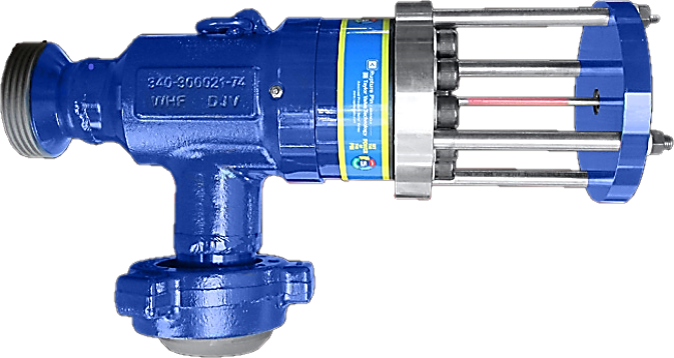
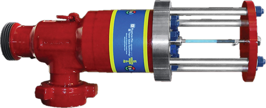
The Premium Oilfield Technologies Caliber® RV7500 Relief Valve was designed for today"s higher-pressure drilling conditions. The valve utilizes a pin buckling system to determine the relief pressure. Each pin is designed to deform when the pressure reaches a predetermined load. All pins go through a stringent quality control process and batch testing to ensure performance at the correct pressure rating.

30 pressure relief valve for mud pump products are offered for sale by suppliers on Alibaba.com, of which mud pump accounts for 36%, pumps accounts for 23%.
A wide variety of pressure relief valve for mud pump options are available to you, You can also choose from new, pressure relief valve for mud pump,as well as from energy & mining, construction works , and machinery repair shops pressure relief valve for mud pump,and whether pressure relief valve for mud pump is 1.5 years, or 3 months.
Note: The FMC Technologies valve is not considered a full flow relief valve; therefore, its main function is a tattletale which indicates the set pressure has been reached. To keep the pressure from continuing to increase, other measures must be taken.

In many liquid piping systems, it is vital that line pressure is maintained within relatively narrow limits. This is the function of the 108 Pressure Relief / Back Pressure Series of the OCV control valves. Installed in the main flow line, the standard Model 108-2 acts as a backpressure or pressure sustaining valve. In this configuration, the valve maintains a constant upstream pressure regardless of fluctuating downstream demand. When used in a bypass line, the same model will function as a relief valve, protecting the system against potentially damaging surges.
Protects system from over pressure by exhausting excess pressure. The valve may only have to operate intermittently to prevent pressure surges that might occur on pump start, pump stop, or sudden downstream valve closure.
Valve allows flow when inlet pressure is above the set-point thus preventing inlet pressure from falling too low. Prevents demand from “robbing” the source, or keeps pump “on its curve.”
RELIEF VALVE – Closed under normal operating pressures. Valve opens when pressure rises to the set point. Valve will close when system pressure drops below set point.
2.) Model 1330 Pressure Relief Pilot, a two-way, normally-closed pilot valve which senses upstream pressure under its diaphragm and balances it against an adjustable spring load. An increase in upstream pressure tends to make the pilot open.
3.) Model 126 Ejector, a simple “tee” fitting with a fixed orifice in its inlet port. It provides the proper pressure to the diaphragm chamber of the main valve depending on the position of the pressure relief pilot.
5.) Model 159 Y-Strainer (standard on water service valves) or Model 123 Inline Strainer (standard on fuel service valves). The strainer protects the pilot system from solid contaminants in the line fluid.
6A / 6B.) Two Model 141-4 Ball Valves (standard on water service valves, optional on fuel service valves), useful for isolating the pilot system for maintenance or troubleshooting.
The Model 1330/2400 Pressure Sustaining Pilot controls the amount of pressure in the upper chamber of the Main valve(s). (Hence, the degree of opening or closing of the Main valve). The upstream pressure increases, the pilot begins to open, decreasing the amount of pressure in the upper chamber of the main valve allowing it to open a proportionate amount, in order to maintain a constant inlet pressure. As the upstream pressure decreases, the pilot begins to close, allowing the pressure in the upper chamber of the main valve to increase causing it to close. This is a constant modulating action compensating for any change in upstream pressure.
For the most comprehensive procedure in sizing Series 108 control valves, it is best to use our ValveMaster software or the guidelines shown here in conjunction with the Performance Charts in the Engineering Section of the OCV catalog.
Bypass pressure control valves are sized based on maximum flow and pressure drop across the valve. The maximum flow through the valve is the pump flow at the desired set point (from the pump curve) minus the minimum system flow. The pressure drop across the valve is the set point minus the pressure at the valve discharge (typically pump suction or storage tank head). Determine the valve’s operating Cv using the maximum flow and pressure drop from the formula:
Size is determined by the amount of flow required to lower the inlet pressure. This relief flow can be difficult to determine, so a general guideline is to use 60% of the rated pump flow. The 108 Series valve is capable of intermittent flows up to 45 ft. per second. Relief valve sizes are typically 50-60% of the mainline size.
Many surge relief, and some bypass pressure control valves are, by their application, subject to pressure differentials that may induce cavitation. When these conditions exist, it may be only on an intermittent basis, causing minimum concern for valve deterioration.
This complex phenomenon cannot be predicted by charts, which index only inlet and outlet pressures. The easiest way to predict cavitation is to let us do the calculation. Simply fax, e-mail or call us and we will provide a graphical analysis and a solution. Provide us:
By combining various control pilots, multiple valve functions can be performed on a single Series 108 Pressure Relief Valve. To find the combination function valve, select the desired features and then the model number. This chart shows only a sample of those most often specified valves. Consult the factory for specific data on the model you selected.
Combination valves can often reduce or eliminate other equipment. Example: If the system requires a Back Pressure Valve and a Check Valve, the check feature can be added as a function of the Back Pressure, Model 108-3.
When valve inlet pressure requires the model 2400 High Pressure Relief pilot, an HP is added to the end of the model number. Example: Standard model 108-2 (inlet ranges from 5 – 300 psi) Model 108-2HP (outlet ranges 200-750 psi)
For maximum efficiency, the OCV control valve should be mounted in a piping system so that the valve bonnet (cover) is in the top position. Other positions are acceptable but may not allow the valve to function to its fullest and safest potential. In particular, please consult the factory before installing 8″ and larger valves, or any valves with a limit switch, in positions other than described. Space should be taken into consideration when mounting valves and their pilot systems.
Series Number – Valve size – Globe or Angle – Pressure Class – Screwed, Flanged, Grooved – Trim Material – Adjustment Range – Pilot Options – Special needs / or installation requirements.

The RV10 safety relief valve is well-suited for overpressure protection of production equipment, including compressors, scrubbers, separators, pipelines or anywhere overpressure protection may be required.

Taylor Valve Technology® is a manufacturer leader in high-quality industrial valves. We deliver safety relief, high-pressure relief, and back pressure relief valves. Our wide array of choke and control valves and pilot-operated valve products are second to none. Products are designed for demanding industrial needs, meeting quality API and ASME Code requirements. High-demand oil & gas industry, chemical plants, power generators, and the processing industry depend on our valves for consistency and durability. Get effective flow control of liquid, steam, and gas. Valves ship from the Taylor Valve Technology, Inc. United States facility. Delivering worldwide, you can depend on quick turnaround times.
Taylor Valve Technology® is a manufacturer leader in high-quality industrial valves. We deliver safety relief, high-pressure relief, and back pressure relief valves. Our wide array of choke and control valves and pilot-operated valve products are second to none. Products are designed for demanding industrial needs, meeting quality API and ASME Code requirements. High-demand oil & gas industry, chemical plants, power generators, and the processing industry depend on our valves for consistency and durability. Get effective flow control of liquid, steam, and gas. Valves ship from the Taylor Valve Technology, Inc. United States facility. Delivering worldwide, you can depend on quick turnaround times.
The RV10 safety relief valve is well-suited for overpressure protection of production equipment, including compressors, scrubbers, separators, pipelines or anywhere overpressure protection may be required.
A relief valve is a Valve which is installed on a pump or pipework to relieve excessive pressure in a positive displacement pump which could cause damage to a pump or system. Relief valves (also known as bypass valve or safety valve) are known as an Internal Relief Valve if installed on the pump itself, and if installed on the system they are known as an External Relief Valve.
Such valves are used on positive displacement pumps as the pumps are designed to prevent recirculation of fluid back to the inlet, meaning the displacement is always forward. However if a valve is closed on the outlet of the pump, or a blockage occurs the pump will continue to build pressure in the outlet pipework and within itself. This can cause pressures to reach dangerously high levels, and the pressure will vent at the weakest part of the system, causing a leak, damage or pump failure.
Such valves work in different ways depending on where they are installed. If installed on a pump the fluid is recirculated within the pump head, preventing the buildup of pressure, however the fluid begins to heat up, and is something which should only be done temporarily as it can lead to pump failure. External relief valves should be used in conjunction with internal relief valves to relieve any excessive pressure in the pipework either back to a vented tank or to dump contents in an emergency to atmosphere.
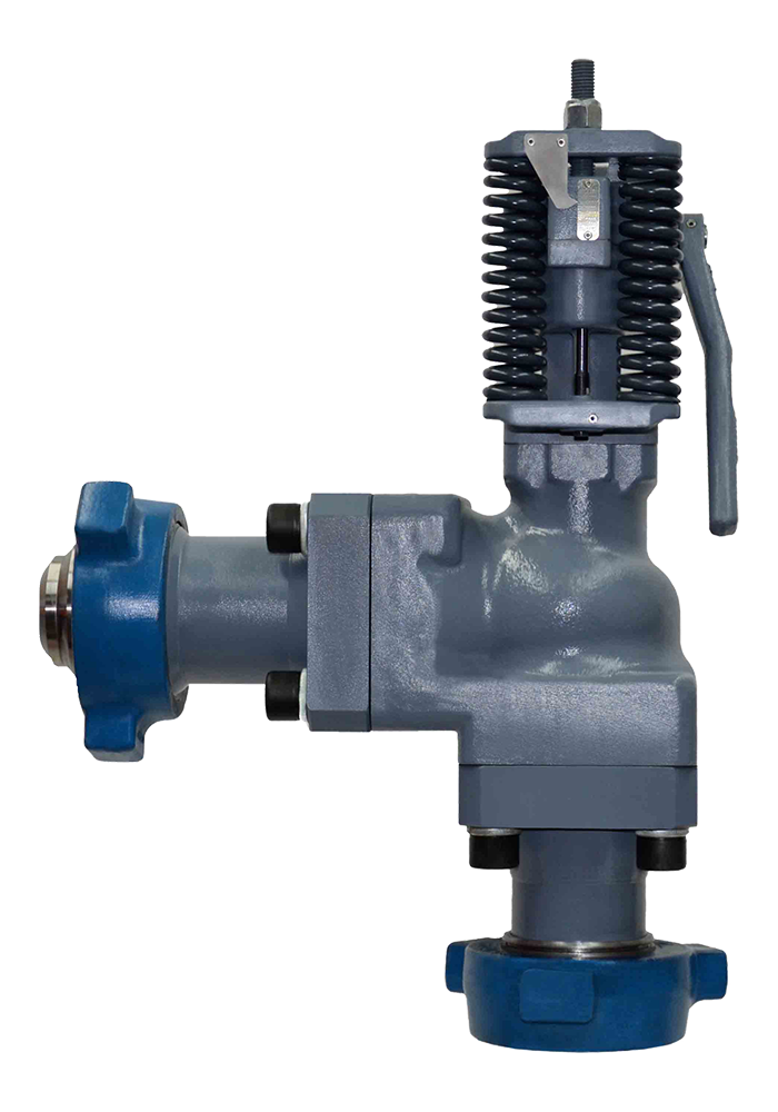
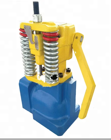
A relief valve design consists of a housing with inlet and outlet connections, a spring within a chamber which keeps a plate in place sealing the discharge. When the valve reaches the set relief pressure, the pressure plate causes the spring to compress revealing the discharge, causing the pressurised contents to vent through the discharge. A set screw or nut is used to set the relief pressure, at the top of the housing and when screwed clockwise, compresses the spring increasing the amount of pressure required to compress the spring and open the valve.
Internal relief valve set pressure is usually set at 10% above the operating pressure of the pump, and external relief valves should be set at 10% higher than the relief valve on the pump to prevent nuisance tripping. Valves are typically calibrated during manufacture and can be set on site with the use of pressure gauges during commissioning. Valves are rated in ranges such as from 0-10 bar, or 10-15 bar so should a valve pressure rating require recalibrating, checks should be made to ensure the setting is inline with the rating of the valve. Equipment should be checked at regular intervals to ensure succesful operation during an emergency.
Relief valves are not always required if the pressure capability of the pump is low, but also if used in conjunction with a product which can solidify when cooled if it enters the relief valve such as Chocolate or Bitumen. If fluid sets within a relief valve this will prevent it from operating as normal as any material which hardens will form a plug and can also cause contamination as it can be very difficult to clean thoroughly.
On some pumps a pressure relief valve is used in conjunction with a pressure regulator which regulates the pump to deliver the required pressure for the system. An analogy often used to describe a pressure regulator is akin to brakes in a car, with and the relief valve being the seat belt. A relief valve should only be relied on for use in emergencies to prevent damage to the pump or system and not as frequent protection for the system.
Power washer pressure relief safety valves from trusted brands such as General Pump, Giant, Fluid Controls, and more are available in options from 1/4 to 1/2 inches and 1200 - 6000 psi. Contact us for help choosing the right pressure unloader valve to suit your pressure washing application.
Pressure-Washer-Parts.com may store and sell products and chemicals that are known to the State of California to cause cancer, birth defects, and other reproductive harm.
New replacement air compressor pressure safety relief valves. Using the correct one for your application is critical for safety. If you need help picking the right one, please call us for assistance.
Safety relief valves help keep pressure washers When predetermined pressure is reached, valve opens and release excess pressure. Installs in outlet of pump head or near burner/coil inlet or outlet on hot water units.

The Dragon’s teams field service team is happy to announce the launch of their full pressure safety valve service both on customer location with mobile testing and at our service facility located at 4500 33 Mile Rd. in Casper, Wyoming. Our “VR” certified shop’s capabilities include repair of all manufacturers’ brands of pressure relief valves ½” up to 8” in size for air, gas, and liquid applications up to 3,000 PSI. Tests and repairs completed are performed and documented in compliance with ASME and NBIC code. With this new service offering, our technicians can assist with new pressure safety valves, tests, repairs, and conversions. Each technician undergoes an extensive training program to ensure that only qualified technicians work on customers’ valves and on their locations. We have the ability to test and repair relief valves which complements our comprehensive well pad maintenance service that includes Quad O-A Flir testing, flame arrestor testing, production equipment preventative maintenance, cathodic protection, valve greasing, and PM program implementation/tracking. We also offer device tracking and accurate data management using the company’s Data Acquisition System. We can track by PSV, location, serial number, and more. Join us for a customer appreciation open house on Friday, April 24th from 11:00 am to 2:00 pm at the Casper facility!


 8613371530291