
mud pump pulsation dampener precharge price

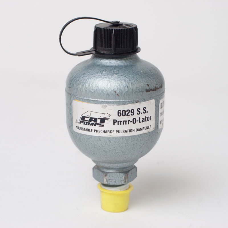
The Pulsation Dampener 3375-0015-3 from the Hypro series assures smooth discharge from piston and plunger pumps. It also reduces peak loading on pump bearings and other internal parts. The Pulsation Dampener 3375-0015-3 extends the system life and minimizes maintenance costs.
As a general guideline, when using two cylinder or four cylinder piston pumps, the dampener charge should be approximantely 1/2 of the pump operating pressure. When using a three or six cylinder pump, te dampener charge should be approximately 2/3 of the pump operating pressure. This pump is rated for up to 1500 psi.

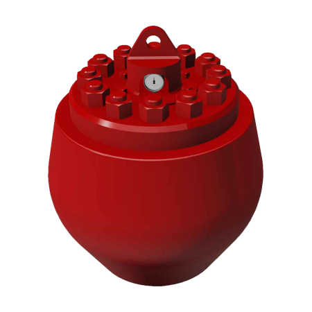
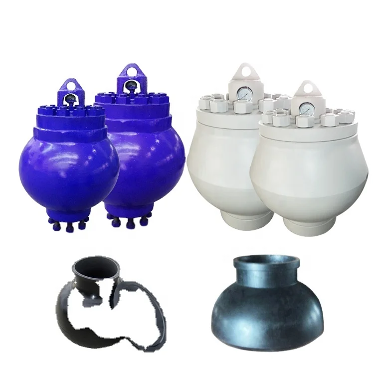
Mud pump pulsation dampeneris the mud pump discharge end main component, installs in the hydraulic end discharge pipe one end, plays the stable pressure and the pressure compensation function, the air bag work pressure is the mud pump work pressure 80%.Attention should be paid to the use of air bag, must be the first pressure relief.The mud pump of F500/F800 USES kb-45 air bag, and the mud pump of F1000/F1300/F1600 USES kb-75 air bag.The middle tie rod produced by our company is made of 35CrMo material, which has a smooth surface after chrome plating and fine grinding, greatly improving the wear resistance and corrosion resistance.
Proper installation and use of pulsation dampener can effectively reduce pressure fluctuations in the discharge system, thus achieving a more uniform fluid flow.In order to achieve a high service life of the air bag, always maintain the recommended ratio between the pump pressure and the air bag precharge pressure (generally not more than 2/3 of the pump discharge pressure, the maximum should not exceed 4.5mpa).
2. In the maintenance of air bag, air bag pressure must be zero, the pump pressure must be zero.Cannot rely on the pressure gauge to judge, because the residual pressure is small, the pressure gauge can not be displayed, but this low pressure will also lead to accidents!

A properly serviced pulsation dampener is critical for your mud pumps’ efficiency, safety, and performance. Unfortunately, there aren’t many resources available to educate personnel on executing safe and effective servicing procedures. Please review the following steps with your personnel for safe pulsation dampener maintenance.
Should you or your personnel have any questions regarding pulsation dampener maintenance, please don’t hesitate to ask. Sigma is more than happy to help you to ensure safe and proper care is being completed on your pulsation dampening equipment.

A well-placed suction stabilizer can also prevent pump chatter. Pump chatter occurs when energy is exchanged between the quick opening and closing of the reciprocating pump’s valves and the hammer effect from the centrifugal pump. Pump isolation with suction stabilizers is achieved when the charge pumps are isolated from reciprocating pumps and vice versa. The results are a smooth flow of pumped media devoid of agitating energies present in the pumped fluid.
Suction stabilizer units can mitigate most of the challenges related to pulsations or pressure surges, even in the most complex piping conditions. The resulting benefits prevent expensive unplanned downtime and decrease costs and inconvenience associated with system replacements and repairs.

Our custom-designed systems will absorb excess energy pulsing through the pump and piping system by creating a low-pressure area to dampen the excess shocks and vibrations. Because a pulsation dampener regulates the release of energy, your system will be better protected and run more smoothly. After installing a pulsation dampener, customers notice that their system:
The pulsation dampeners shall be installed properly to reduce the pressure fluctuation and smooth the liquid flow. In order to extend the lifespan of the air bag, it is highly recommended to maintain the suggested proportion of the pump pressure to the pre-charge pressure of the air bag for the pulsation dampeners. Generally, the pump pressure shall be 2/3 that of the discharge pressure and no more than 4.5MPa.
2. During maintenance, the pump pressure and the pressure inside the pulsation dampeners shall be zero. Since the residual pressure is generally small and can not be indicated on the pressure gauge, user shall confirm the pressure carefully to avoid accident caused by low pressure.

For both onshore and offshore drilling applications, American Block’s pulsation dampeners are manufactured and hydro-tested by our legacy in-house team of experts. These dampeners are designed to meet the most demanding large-volume and high-slurry pump applications and provide ease of installation and elongated service life for the Operator.
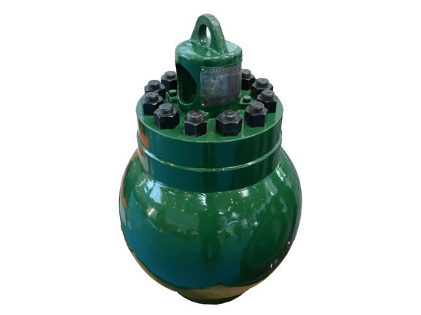
ATO supplies forged and casted steel pulsation dampeners which are inter-changeable and compatible with Hydril series "K" dampeners, Emsco series "PD" dampeners and Bomco series "KB" dampeners. These units are dependable and reliable with API connections
should be mounted in the vertical position (refer to Figure 1-3 and 1-4 for mounting options) with the mating flange connection at the bottom. The discharge dampener should be mounted as close as possible to the discharge port of the pump. If possible, it is advantageous that the dampener be mounted in such a way that the fluid stream is directed towards the fluid opening (see Figures 1-3 and 1-4) for maximum performance.
The correct precharge is vital for maximizing efficiency of the pulsation dampener. Generally, precharge pressure is based on the average operating pressure of the system, but precharge can be affected by other system parameters; for example. the use of MWD tools. For these applications, consult qualified Hydril personnel for correct precharging instructions.
We always think and practice corresponding to the change of circumstance, and grow up. We purpose at the achievement of a richer mind and body as well as the living for Mud Pump Pulsation Dampener Precharge Pressure, , , , First company, we understand each other. Further more company, the trust is getting there. Our enterprise normally at your provider anytime.

The installation of properly sized pulsation dampeners minimize vessel costs while protecting the pump and piping system and improving process efficiency and accuracy.
A pulsation dampener reduces or eliminates the variations in pressure and flow produced by reciprocating pumps. In many applications, low frequency pressure waves cause problems within a given piping system and/or process. Eccentric, cam-driven pumps are probably the most commonly applied for services that require pulsation dampening, e.g., metering pumps and reciprocating (power) pumps.
Pulsation dampeners are found in a variety of designs, but for our purposes we will focus on only gas-charged pulsation dampeners, which rely on a calculated volume of compressed gas, usually Nitrogen, which is alternately compressed and expanded in synchronization with the pump plunger to reduce or eliminate pressure pulsations. This gas volume is normally separated from the process fluid by a flexible membrane. Common membrane designs include elastomeric bladders, PTFE diaphragms, PTFE bellows or stainless steel bellows.
Pressure waves or pulses are a consequence of the alternating acceleration and deceleration of fluid velocity corresponding to the travel of the piston or plunger. The pattern and amplitude of these pulses varies with pump configuration, specifically the number and size of pistons, as well as fluid compressibility factors.
It is precisely the fluid volume above mean on the discharge cycle of each stroke, which induces these pressure pulsations into a piping system. The number of pistons offered by the pump-given that all are of identical diameter and equally phased-displace a known peak volume above mean. These constants may be influenced by fluid compressibility, but for the purpose of this explanation we’ll assume none at this point. A pulsation dampener absorbs only that portion of piston displacement above mean flow, and then stores it momentarily before discharging it during the portion of the cycle below mean flow (on the suction stroke).
A simplex pump displaces a volume of fluid above mean that is equal to about 60 percent of total displacement. A duplex pump displaces a lower fluid volume above mean, approximately half that of a simplex pump. Pumps of three or more pistons of equal diameter, stroke length and proportionally phased will always present a very small fluid volume above mean to the piping system. A triplex pump, for example, produces about a 4 percent peak, as long as fluid compressibility factors and pump efficiencies are not at issue.
These smaller fluid volumes are accounted for by the crank angle of each of the cylinders. Triplex pumps are offset by 120-deg. Quadruplex pumps are set apart at 90-deg offsets; quintuplex pumps are offset 72-deg, and so on. It is the resulting overlap in pulses that yield the smaller fluid volumes above mean.
Fluid velocity gradients follow the same mechanical velocity gradients of the eccentric cam that drives the piston(s). Halfway through the piston’s forward travel (discharge stroke), fluid velocity between the discharge check valve and the pulsation dampener begins to decay. The corresponding drop in pressure causes the membrane inside the dampener to expand since the internal gas pre-charge pressure is now higher than the line pressure. The (stored) fluid now being displaced by the pulsation dampener maintains velocity downstream of the dampener thereby reducing, if not eliminating, any downstream pulsations.
Note: A pulsation dampener removes pulses only from the line downstream of the dampener-not upstream. That’s why it’s always recommended that discharge dampeners be installed as close to pump discharge nozzles as possible. In an application of a dampener for suction stabilization (reduction of acceleration head losses), it is the velocity gradient between the supply vessel and the suction nozzle that is minimized.
Let’s begin by defining the pump details required to properly size a pulsation dampener. We will use these values in a sample calculation to help clarify the process.
The result of the previous calculation is then divided by a constant. As noted previously, the constant is a function of pump configuration. We use a conservative 1.5 for simplex pumps, 2 for duplex pumps, and 7 for triplex pumps. Remember-if the fluid is compressible, then the constant may have to be adjusted downward.
Fluid volumes above mean are well within the range of these constants. The fluid pulse above mean flow from a simplex pump, for example, is about 60 percent. When we divide full stroke displacement by 1.5 the result is a conservative 67 percent. The divisor 7 that we use for triplex pumps allows for a nominal 14 percent fluid volume above mean. While 14 percent is far above the actual 4 percent produced by triplex pumps, the higher volume is an allowance for practical reasons, specifically size and nozzle limits. Otherwise, the result would be a very small dampener relative to pump size.
Ranges of (process) temperature and pressure must be considered in any sizing calculations for pulsation dampeners. Compensations must be made for temperature variations, which affect gas density, and dynamic variations in system pressure, since sizing is based on a set pre-charge pressure.
The objective is to select a dampener that is adequately sized to handle a range of operating pressures with a single pre-charge pressure. Remember that the gas pre-charge pressure should always be based on the minimum operating pressure as the pulsation dampener will have no effect when the system pressure is below the pre-charge pressure.
Changes in ambient temperature can also influence gas density, but they’re generally disregarded for the purposes of pulsation dampener sizing. It is usually sufficient to make seasonal adjustments to pre-charge pressures, if necessary. Temperature and pressure calculations are recommended to be done using absolute values (Kelvin for temperature and BarA or PSIA for pressure).
Some fluids are highly compressible, such as cryogenics, olefins, liquefied gases, anhydrous ammonia, etc. In these instances, the benefit of lower pulsations from multiple piston pumps may be somewhat compromised. Fluid compression occurs during the leading edge of the (eccentric) crank angle. Given sufficient pressure and a high enough compressibility factor, there may be little or no overlap of pulses at all-in which case, adjustments have to be made and pulsation dampeners with larger gas volumes should be selected.
By installing a properly-sized pulsation dampener, users can reduce or eliminate pipe shake, vibration and noise. The result is a continuous flow of product which is required in many metering, mixing and spraying applications. Reduced pressure pulsations minimize long-term damage to instrumentation and pump components while improving the accuracy of many flowmeters and increasing pump efficiency.
6500 Brittmoore Houston, Texas 77041-5109 281-931-8550 888-MUD-PUMP www.lewco-equip.com FAX 713-856-5341February 24, 2003 Page 1 of 9 Table of Contents
The Model L20-7500-DNV Discharge Pulsation Dampener....................................3Assembly Drawing ........................................................................................................4Parts List ........................................................................................................................5Mounting Instructions ..................................................................................................6Precharge Pressure Levels ...........................................................................................7Overhaul Kit ..................................................................................................................8Recommended Spare Parts ..........................................................................................9
6500 Brittmoore Houston, Texas 77041-5109 281-931-8550 888-MUD-PUMP www.lewco-equip.com FAX 713-856-5341February 24, 2003 Page 2 of 9 The Model L20-7500-DNV Discharge Pulsation DampenerThe LEWCO pulsation dampener is designed to counter the effect of pulsations often associatedwith positive displacement reciprocating pumps. The L20-7500-DNV has a dampening volumeof 20 gallons and is rated for a maximum allowable working pressure of 7,500 psi. The L20’sdesign focuses on durability and simplicity. Since the L20 uses a minimum number of parts, it iscompletely field serviceable, thereby eliminating costly shop repairs and down time. Areplaceable bottom plate having a 4 1/16” API 10,000 connection comes as a standard feature,which is ideal when working with abrasive or corrosive fluids. The large top flange allows forreplacement of the diaphragm bladder without removing the unit from the line. The stainlesssteel charge valve and pressure gage are located on the top flange and protected by a heavy-dutycover that also serves as a lifting eye. Each complete unit is hydrostatically tested to 11,250 psibefore shipment. Ask for LEWCO part number C305026
6500 Brittmoore Houston, Texas 77041-5109 281-931-8550 888-MUD-PUMP www.lewco-equip.com FAX 713-856-5341February 24, 2003 Page 3 of 9 Assembly Drawing Model L20-7500-DNV Discharge Pulsation Dampener P/N C305026
6500 Brittmoore Houston, Texas 77041-5109 281-931-8550 888-MUD-PUMP www.lewco-equip.com FAX 713-856-5341February 24, 2003 Page 4 of 9
Read All Instructions Before Attempting to Install This Dampener.Use Safe Lifting Practices Whenever The Dampener Is Installed Or Moved. The Dampener Lifting Cap Is Designed To Lift The Dampener Only. The Dampener Must Be Completely Unflanged Before It Is Lifted.
The LEWCO Model L20-7500-DNV dampener should be mounted preferably in the verticalposition. When other conditions exist, an angular or inverted installation is acceptable and doesnot impede dampener performance. However, increased corrosion could occur due to trappedfluid.
LEWCO dampeners use ANSI and API flanged connections and NPT type threaded connections.For flanged connections, position the dampener on a gasket and mating flange so that it iscentered. Install nuts hand tight. Cross-tighten nuts one turn at a time to proper torque to insureuniform load. The torque value for the 1-1/8” stud is 778 ft. lbs.
6500 Brittmoore Houston, Texas 77041-5109 281-931-8550 888-MUD-PUMP www.lewco-equip.com FAX 713-856-5341February 24, 2003 Page 6 of 9 Precharge Pressure Levels Model L20-7500-DNV Discharge Pulsation Dampeners
x For maximum operating efficiency, the precharge pressure should be 75 percent of the minimum operating system pressure or 2,000 psig* , whichever is lower.
x For normal operating conditions, the precharge pressure should be 50 percent to 60 percent of the average operating system pressure or 2,000 psig*, whichever is lower.
x For limited operating conditions, the precharge pressure should be maintained between 30 percent to 75 percent of the average system operating pressure or 2,000 psig*, whichever is lower.
PRECHARGING General Precharging Directions Model L20-7500-DNV Discharge Pulsation DampenerThe charging valve and the pressure gauge are located under the dampener lifting cap, and theyare exposed by removing the lifting cap. Before precharging the dampener, make sure all coverstud nuts are tightened evenly and no pressure is on the operating system.
Connect one end of the hose assembly to a standard commercially available nitrogen bottle andthe other end to the charging valve located at the top of the dampener. Precharge from a standard224 cubic foot 2,200 psig nitrogen bottle equipped with a pressure regulator. Open the bottleregulator valve until recommended precharge pressure shows on the regulator gauge. Slowlyopen the charging valve on the dampener by turning the top hex nut 3 to 4 complete turnscounter-clockwise.
Allow pressure to increase in the dampener until dampener pressure gauge reads specifiedprecharge pressure. This process normally takes 5 to 15 minutes. Dampener gauge and regulatorgauge should read the same and be equal to the specified precharge pressure. Close theprecharge valve, then close the regulator valve at the nitrogen bottle. The sound of escaping gasmay be heard at the charging valve until the regulator is closed.
6500 Brittmoore Houston, Texas 77041-5109 281-931-8550 888-MUD-PUMP www.lewco-equip.com FAX 713-856-5341February 24, 2003 Page 7 of 9 Overhaul Kit Model L20-7500-DNV Discharge Pulsation Dampener
6500 Brittmoore Houston, Texas 77041-5109 281-931-8550 888-MUD-PUMP www.lewco-equip.com FAX 713-856-5341February 24, 2003 Page 8 of 9 Recommended Spare Parts Model L20-7500-DNV Discharge Pulsation Dampener
6500 Brittmoore Houston, Texas 77041-5109 281-931-8550 888-MUD-PUMP www.lewco-equip.com FAX 713-856-5341February 24, 2003 Page 9 of 9


 8613371530291