
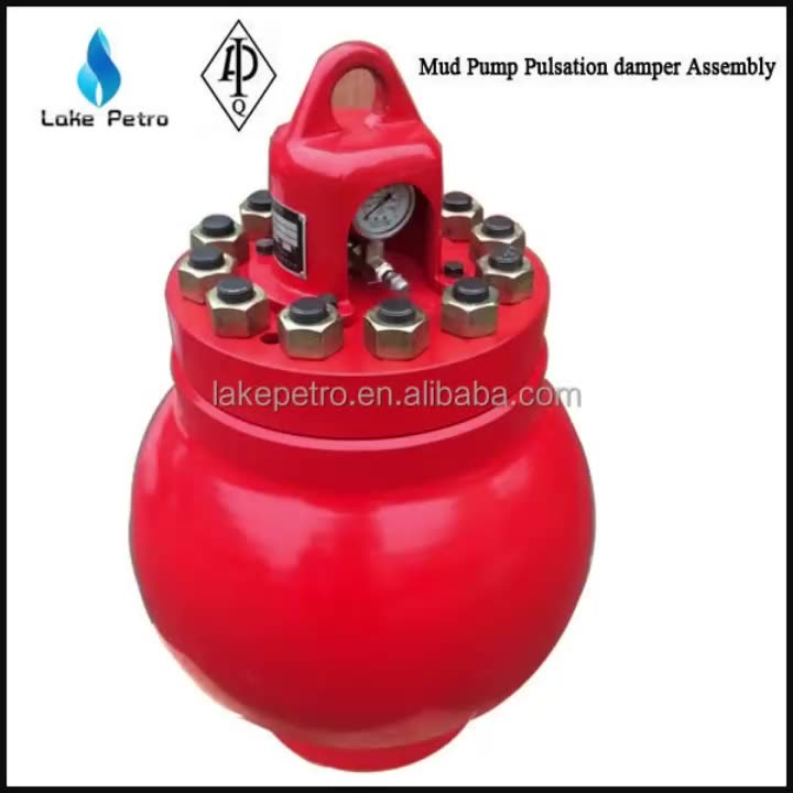
mud pump pulsation dampener precharge pressure supplier
A properly serviced pulsation dampener is critical for your mud pumps’ efficiency, safety, and performance. Unfortunately, there aren’t many resources available to educate personnel on executing safe and effective servicing procedures. Please review the following steps with your personnel for safe pulsation dampener maintenance.
Should you or your personnel have any questions regarding pulsation dampener maintenance, please don’t hesitate to ask. Sigma is more than happy to help you to ensure safe and proper care is being completed on your pulsation dampening equipment.
Premium is proud to offer a full-line of Pulsation Dampener Solutions. Our PD series dampeners are available in 5 ,10 & 20 gallon models and are rated for 5000 or 7500psi.
They are available in 1500 psi, 3000 psi, and 5000 psi ratings. Replacement diaphragms and parts are offered for 10 and 20 gallon, Mattco and Hydril pulsation dampeners. Also available are stabilizers, bottom plate gaskets, charging valves, pressure gauges (0-6000 psi), plates, screws, and lock washers.
Our custom-designed systems will absorb excess energy pulsing through the pump and piping system by creating a low-pressure area to dampen the excess shocks and vibrations. Because a pulsation dampener regulates the release of energy, your system will be better protected and run more smoothly. After installing a pulsation dampener, customers notice that their system:
Our well-equipped facilities and superb good quality control throughout all stages of manufacturing enables us to guarantee total buyer gratification for Mud Pump Pulsation Dampener Precharge Pressure, , , , We welcome shoppers, enterprise associations and buddies from all areas of your environment to speak to us and request cooperation for mutual gains.
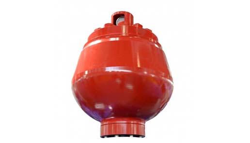
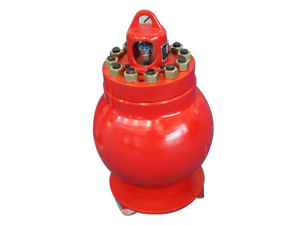
Mud Pump Pulsation Dampener is usually installed on the discharge line to reduce the fluctuation of pressure and displacement of the drilling mud pump.
Mud Pump Pulsation Dampener is a pneumatic device built into the outflow line of each UUD pump to dampen the pressure fluctuations resulting from the action of the pump. Although presented as a surge tank, this device is really a device that can be tuned to greatly diminish the output pulsations transmitted downstream from the mud pump. Unfortunately, the effectiveness of the pulsation dampener is a function of both output pump pressure and frequency of the pump pulsations.
The pulsation dampeners shall be installed properly to reduce the pressure fluctuation and smooth the liquid flow. In order to extend the lifespan of the air bag, it is highly recommended to maintain the suggested proportion of the pump pressure to the pre-charge pressure of the air bag for the pulsation dampeners. Generally, the pump pressure shall be 2/3 that of the discharge pressure and no more than 4.5MPa.
2. During maintenance, the pump pressure and the pressure inside the pulsation dampeners shall be zero. Since the residual pressure is generally small and can not be indicated on the pressure gauge, user shall confirm the pressure carefully to avoid accident caused by low pressure.
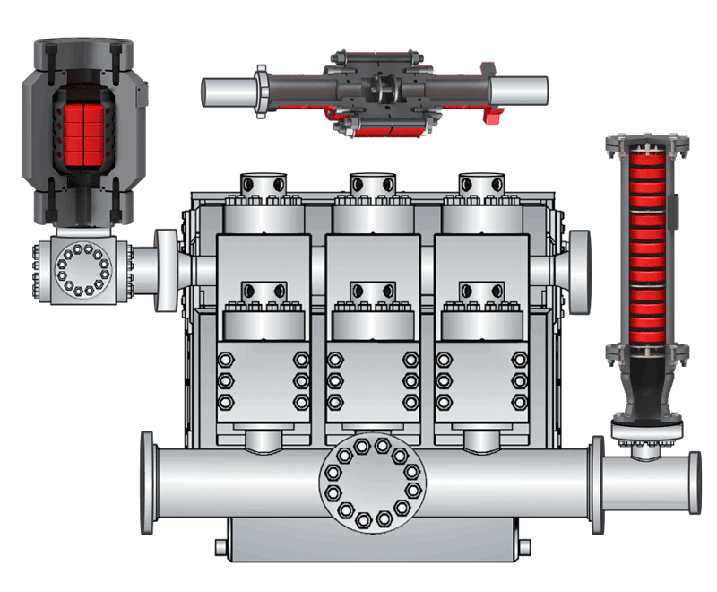
ATO supplies forged and casted steel pulsation dampeners which are inter-changeable and compatible with Hydril series "K" dampeners, Emsco series "PD" dampeners and Bomco series "KB" dampeners. These units are dependable and reliable with API connections
should be mounted in the vertical position (refer to Figure 1-3 and 1-4 for mounting options) with the mating flange connection at the bottom. The discharge dampener should be mounted as close as possible to the discharge port of the pump. If possible, it is advantageous that the dampener be mounted in such a way that the fluid stream is directed towards the fluid opening (see Figures 1-3 and 1-4) for maximum performance.
The correct precharge is vital for maximizing efficiency of the pulsation dampener. Generally, precharge pressure is based on the average operating pressure of the system, but precharge can be affected by other system parameters; for example. the use of MWD tools. For these applications, consult qualified Hydril personnel for correct precharging instructions.

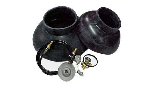
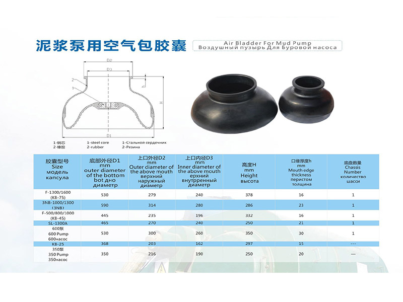
Mud pump pulsation dampeneris the mud pump discharge end main component, installs in the hydraulic end discharge pipe one end, plays the stable pressure and the pressure compensation function, the air bag work pressure is the mud pump work pressure 80%.Attention should be paid to the use of air bag, must be the first pressure relief.The mud pump of F500/F800 USES kb-45 air bag, and the mud pump of F1000/F1300/F1600 USES kb-75 air bag.The middle tie rod produced by our company is made of 35CrMo material, which has a smooth surface after chrome plating and fine grinding, greatly improving the wear resistance and corrosion resistance.
Proper installation and use of pulsation dampener can effectively reduce pressure fluctuations in the discharge system, thus achieving a more uniform fluid flow.In order to achieve a high service life of the air bag, always maintain the recommended ratio between the pump pressure and the air bag precharge pressure (generally not more than 2/3 of the pump discharge pressure, the maximum should not exceed 4.5mpa).
2. In the maintenance of air bag, air bag pressure must be zero, the pump pressure must be zero.Cannot rely on the pressure gauge to judge, because the residual pressure is small, the pressure gauge can not be displayed, but this low pressure will also lead to accidents!

A Pulsation Dampener is an inline dampening device used to smooth out pulsations in a pump’s output. They are used alongside a pump as a mounted accessory to help achieve certain flow rates for an application. They can be used with a variety of Positive Displacement Pumps which typically generate a pulsed flow (Diaphragm Pumps, Peristaltic Pumps, Dosing Pumps, Piston Pumps etc)
Pulsation Dampeners are required in some process applications when the customer needs smooth flow into the next phase of the production line, for example, to get an accurate reading through a flow meter or to fill a hopper consistently. On the flip side, Dampeners can be used to reduce water hammer effects through pipework. Water hammer is where the pump causes the pipes to vibrate and potentially fail, a smooth flow from a Pulsation Dampener reduces this.
For example, Diaphragm Pumps inherently produce a very turbulent discharge flow meaning that in some instances a Pulsation Dampeners are required to give a smooth pulse-free flow.
In the Tapflo UK range, we focus on Pulsation Dampeners for Diaphragm and Peristaltic Pumps, although we can also supply them for other pump technologies.
The Active Pulsation Dampener works by supplying an equal pressure to the pulsation supplied by the pump. The Dampener supplies this pressure during the low-pressure points of the pump’s operation, as the pressure drops between pump strokes creating a pulsating flow. The pressure supplied by the dampener decreases pressure variations, therefore producing a steady flow from your Diaphragm Pump. You can see the pressure drops and Pulsation Dampener benefits in action in the diagram below.
Tapflo supplied a 2” Air Operated Diaphragm Pump to a bleach factory, the customer used the T400 PTT for a couple of days and then called us to explain that the bleach line, running along the roof of his production facility, was shaking. Due to the nature of the product being pumped health and safety on site could not allow this to continue.
To support our Peristaltic Pump customers, Tapflo offers an in-line Pulsation Dampener for our PT and PTL Series’. They can reduce the pulsation of your PT Pump by as much as 90% to reduce the vibration and water hammer effects on pipework. Another benefit of this accessory is its ability to be installed on-site horizontally or vertically for flexible installation.
Pulsation problems often start on the suction side. Pulsation or cavitation is caused by the variation of fluid movement within a contained system. Since fluid is non-compressible, the energy produced by this pulsation or cavitation must be compensated for. With the introduction of pulsation equipment into a system this energy now has a place to expend itself. Without the pulsation equipment involved in your pumping system, the pulsation or cavitation that is present can lead to the following:
For more information about pulsation dampeners, we sat down with Brandon Dalrymple and Nathan Ackeret fromBlacoh Fluid Control(manufacturer of pulsation dampeners, surge suppressors, and inlet stabilizers), and asked them to answer a few of our customers’ most common questions about pulsation dampeners.
Pulsation dampeners absorb the energy from the pulse wave created by a positive displacement pump, much like a shock absorber on a vehicle. Absorbing those pulse waves protects pipe welds and supports, and system components from damage due to pressure or excess movement.
A pulsation dampener creates an area of low pressure in the system with enough volume to absorb the pulsation. The pulsation dampener has a membrane with a "cushion" of compressible gas/air behind it that flexes to absorb the pulse, allowing a laminar flow downstream of the dampener.
Pulsation dampeners are commonly used wherever a positive displacement pump discharges flow in an unsteady manner, and where the pulse is not desired for the piping system. Air operated double diaphragm, metering and hose/peristaltic pumps typically benefit from a pulsation dampener.
The type of pulsation dampener used is typically defined by where they are placed in the system, and what they need to do. For example, "pulsation dampeners" are on the downstream side of the pump, "inlet stabilizers" are on the inlet side of the pump, and an accumulator or "surge suppressor" is used next to a valve or other device that restricts the flow in a system.
This video shows where you would place an inlet stabilizer, and how it is used to reduce the pulsation with an air operated diaphragm pump in suction lift conditions.
If you"re experiencing problems with rattling pipes, intermittent flow, water hammer, or pulsations in your system, don"t ignore it. Take the steps necessary to control these symptoms to prevent system deterioration down the road.
Need help with pulsations or water hammer problems? Ask us about it! We gladly provide technical assistance to businesses in Wisconsin and Upper Michigan.

[0001] The present application relates generally to the operation of fluid transfer systems and, more specifically, to providing a precharge manifold decrease ramp-up time in a fluid transfer system.
[0002] Fluid transfer systems circulate fluid from a pump to downstream equipment. Pulsations within the fluid can deteriorate the integrity of the pump and that of other equipment downstream from the pump. Pulsation control is the process of reducing pulsations within the fluid of a fluid transfer system. Reducing pulsations within a fluid transfer system can increase the longevity of the equipment as well as the efficiency of the overall system. Among the improvements desirable are reduced pulsation amplitudes from pumps to the downstream system and greater flexibility in integration of pulsation dampeners with other elements of an overall pump system.
[0003] A pulsation control device is designed to reduce pulsations in a fluid transfer system based on parameters of the fluid transfer system while the system is fully operational. During various periods of operation, such as while the fluid transfer system is ramping up or ramping down, the fluid transfer system might operate under different parameters and as such, the pulsation device does not perform at the peak efficiency. Therefore, there is a need for improved control to ensure that a pulsation control device performs under near operational status during period of when the system is not actually under fully operational conditions.
[0004] In one aspect thereof, a pulsation dampener system includes a pump that pumps fluid through the pulsation dampener system and a pulsation dampener, located downstream from the pump, for dampening residual pulsations within the fluid. The system also includes a wye pipe located downstream of the pulsation dampener that splits the fluid into two or more flow paths. A first flow path for the fluid is located at the wye, wherein the first flow path and increases the pressure of the fluid. A second flow path for the fluid is located at the wye, that allows the fluid to flow unrestricted. The system also includes piping that receives the fluid from the first flow path and the second flow path and discharges the fluid further downstream. The system also includes a pressure sensor located upstream of the wye pipe and configured to detect the pressure of the fluid at the pulsation dampener. The system also includes a second sensor or some user supplied monitor downstream of the Wye to monitor system pressure.
[0005] In another aspect thereof method for dampening pulsation includes receiving fluid from a pump. The method also includes dampening pulsations in the fluid, using a pulsation dampener. The method further includes detecting a pressure of the fluid at the pulsation dampener. The method also
includes splitting the fluid into two or more paths downstream of the pulsation dampener, the two or more paths include a first flow path and a second flow path. Additionally, the method includes increasing the pressure of the fluid, when the fluid flows through the first flow path.
[0008] FIG. 1 illustrates a simplified cross-sectional and somewhat schematic view of a reciprocating pump system employed within pulsation dampener system with multiple flow paths according to an embodiment of the present disclosure;
[0009] FIG. 2 illustrates a simplified, somewhat cross sectional view of a typical pulsation dampener employed within pulsation dampener system with multiple flow paths according to an embodiment of the present disclosure;
[0010] FIG. 3A illustrates diagrammatic view of a pump dampener system including a pulsation dampener installed between a pump and a multiple flow paths according to various embodiments of the present disclosure;
[0012] FIG. 4 illustrates a flowchart of a fluid delivery and pulsation dampening system with multiple flow paths according to various embodiments of the present disclosure; and
[0013] FIG. 5 illustrates a flowchart of a fluid delivery and pulsation dampening system with multiple flow paths according to various embodiments of the present disclosure.
be construed in any way to limit the scope of the disclosure . Those skilled in the art will understand that the principles of the present disclosure may be implemented in any suitably arranged piping manifold dampener that can be used to control or partially control pulsation amplitudes.
[0015] Reciprocating systems, such as reciprocating pump systems and similar equipment, operate in many types of cyclic hydraulic applications. For example, reciprocating mud pump systems are used to circulate the mud or drilling fluid on a drilling rig. Pressure peaks as well as the magnitude of pressure pulsations within the pumped fluid hasten the deterioration of the pump, the pump’s fluid end expendable parts, and equipment downstream from the pump, such as measurement equipment used to determine drilling parameters. Failure to control such pressure peaks and the magnitude of the pulsation inevitably affects the operating performance and operational life of the pump, pump fluid end expendable parts and all upstream or downstream components. Additionally, pressure peaks as well as the magnitude of pressure pulsations within the pumped fluid can interfere with instrument signal detection and/or quality of the signal detection.
[0016] Pulsation control equipment is typically placed immediately upstream or downstream from a reciprocating pump. Pulsation control equipment aids in reducing pump loads and minimizing pulsation amplitudes to the pump, the pump’s fluid end expendable parts, and to equipment upstream or downstream from the pump. As a result, pulsation control equipment increases the relative operating performance and life of the pump, the pump’s fluid end expendable parts, and any equipment upstream or downstream from the pump. The size and configuration of pulsation control equipment is proportional to the volume of desired fluid displacement per stroke of the pump and the maximum allotted magnitude of the pressure peaks and magnitude of the pressure pulsations that may be experienced by the pump system during each pulsation.
[0017] Different pulsation dampening systems have been developed. Common types of pulsation dampeners are a hydro-pneumatic dampener, or a gas-charged pressure vessel. A gas-charged pressure vessel contains compressed air or nitrogen and a bladder or bellows that separates the process fluid from the gas charge. A gas-charged pressure vessel can be cylindrical or roughly spherical shaped. Gas-charged pulsation dampeners may be either flow through or appendage type devices. To optimize the pulsation dampening effect, it is often preferable that the pulsation dampener be installed as close as possible to the pump discharge. At such locations, however, the presence of the pulsation dampener may interfere with installation of other system components, such as a strainer.
[0018] Regardless of the type of dampener, the performance of a pulsation dampener diminishes when the pressure of the fluid from the pump is too far from the gas precharge pressure range that the dampener is designed to handle. For example, the gas-charged pulsation dampener design typically requires the gas precharge pressure be slightly below the system pressure during normal operations, and that the pulsation dampener be properly sized for the system. Even when a pulsation dampener is installed in a drilling system, pulsations may be experienced further downstream from the pumps when the pulsation dampener is not properly sized or precharged for the system. For example, an undersized
dampener cannot adequately compensate for pressure and flow fluctuations, while an oversized dampener will act as an accumulator, storing too much fluid and causing slow stabilization and delayed response to system changes. Another example is the dampener precharge pressure is too high for the system pressure, thus the system pressure cannot compress the discharge dampener precharge pressure to engage the gas to allow pulsation control to take place. When the pressure of the fluid within the pipeline is ramping-up to a pressure suitable for the drilling operation (which corresponds to a proper sized pulsation dampener), the pulsation dampener can be considered oversized since the pressure of the fluid is less than the pressure that is suitable for drilling operations. As a result, pulsations can progress downstream, since the pulsation dampener is oversized during the ramp-up period. These downstream pulsations can cause damage to the various downstream components (both equipment and sensors), increased audible noise, increase noise in sensor readings related to the drilling operation, and reduce performance of the drilling operation, when the pressure of the system is not within the pressure range the pulsation dampener is designed to handle.
[0019] FIG. 1 illustrates a simplified cross-sectional and somewhat schematic view of a reciprocating pump system 100 employed within a pulsation dampener system with multiple flow paths, according to an embodiment of the present disclosure. Generally, the reciprocating pump system 100 includes a pump suction and/or discharge pulsation control product including a gas-charged pulsation dampener or a reactive pulsation dampener according to an embodiment of the present disclosure. The reciprocating pump system 100 may employ a reciprocating pump of a type well-known and commercially available. The pump within the reciprocating pump system 100 is configured to reciprocate one or more plungers or pistons 101 (only one shown in FIG. 1). Each piston or plunger is preferably connected by a suitable rotatable crankshaft (not shown) mounted in a suitable“power end” housing 102. Power end housing 102 is connected to a fluid end structure 103 configured to have a separate pumping chamber 104 for each piston or plunger 101. Pumping chamber 104 is exposed to its respective piston or plunger 101. One such chamber 104 is shown in FIG. 1.
[0020] More specifically, FIG. 1 illustrates a simplified cross-sectional view through a typical pumping chamber 104. Fluid end 103 includes housing 105. Pumping chamber 104 receives fluid from inlet manifold 106 by way of a conventional poppet type inlet or suction valve 107 (only one shown). Piston or plunger 101, projecting at one end into chamber 104, connects to a suitable crosshead mechanism, including crosshead extension member 106. Crosshead extension member 106 is operably connected to a crankshaft or eccentric (not shown) in a known manner. Piston or plunger 101 also projects through a conventional liner or through conventional packing 109, respectively. Each piston or plunger 101 is preferably configured to chamber 104. Each piston or plunger 101 is also operably connected to inlet manifold 106 and discharge piping manifold 110 by way of a suitable suction valve 107 or discharge valve 111, as shown. Inlet manifold 106 can include a suction piping manifold that typically receives fluid from suction stabilizer (not shown in FIG. 1) or a suction piping with a suction stabilizer. Discharge piping manifold 110 typically discharges into a discharge dampener (not shown in FIG. 1). Valves 107 and 111 are of conventional design and typically spring biased to their respective closed positions. Valves
[0021] Those skilled in the art will recognize that the techniques of the present disclosure may be utilized with a wide variety of single and multi-cylinder reciprocating piston or plunger power pumps as well as possibly other types of positive displacement pumps. As one example, the number of cylinders of such pumps may vary substantially between a single cylinder and essentially any number of cylinders or separate pumping chambers. Those skilled in the art will also recognize that the complete structure and operation of a suitable pump system is not depicted or described herein. Instead, for simplicity and clarity, only so much of a pump system as is unique to the present disclosure or necessary for an understanding of the present disclosure is depicted and described.
[0022] Conventional pump systems, such as the reciprocating pump system 100 shown in FIG. 1, typically include a dampener system. FIG.2 illustrates a simplified dampener system 200. The dampener system 200 is a cross sectional view of a typical pulsation dampener 205, according to an embodiment of the present disclosure. Pulsation dampener system 200 includes a pulsation dampener 205 affixed to a pipeline 212. The pulsation dampener 205 includes a diaphragm 202, a liquid chamber 204 containing a liquid, a gas pressure chamber 206 containing a gas, and an inlet 210. FIG. 2 does not limit the scope of this disclosure to any particular implementation of a drilling system.
[0023] Pulsation dampener 205 dampens low frequency pulsations and pressure pulsations by reducing the lower frequency energies created by the pumping actions. Pulsation dampener 205 dampens pulsations contained within the fluid flowing through the pipeline 212. In certain embodiments, pulsation dampener 205 is located above the pipeline 212.
[0024] Pulsation dampeners, such as the pulsation dampener 205, are either directly attached to the discharge manifold 110 of FIG. 1, or located downstream of the pump. Generally, the pulsation dampener 205 receives“fluid” (which may be entirely liquid or which may include suspended solids - i.e., a slurry) at an inlet 210. The inlet 210 can be connected to the discharge piping manifold 110 of the reciprocating pump system 100 of FIG. 1 either directly or by intervening piping (not shown). The connection allows pumped fluid to enter the liquid chamber 204, via the inlet 210, of the pulsation dampener 205.
[0025] Fluid enters and exits the liquid chamber 204 via the inlet 210. The gas pressure chamber 206 is filled with pressurized gas to a predefined pressure, known as precharge. In certain embodiments, the pressurized gas is nitrogen (N2) or another gas. A diaphragm 202 separates the gas pressure chamber 206 from the liquid chamber 204. The pressurized gas in the gas pressure chamber 206 minimizes pressure variation of the fluid by absorbing system shocks, pipe vibration, water hammering, pressure fluctuations, and the like. By minimizing pulsation in the system, the longevity of various components such as regulators, pumps, valves, sensors, and so forth is increased since wear on the components caused by the pulsations is reduced.
[0026] As the fluid passes into the liquid chamber 204 pressure from the liquid can be exerted on the diaphragm 202 causing the diaphragm 202 to compress the gas within the gas pressure chamber 206. When the pressure of gas within the gas pressure chamber 206 is increased, the gas occupies less volume, thereby increasing the volume of the liquid chamber 204. Pulsations within the fluid are then dispersed across the volume of the pressurized gas in the gas pressure chamber 206. The volume and subsequent pressure of the gas in the gas pressure chamber 206 increases and reduces in response to pressure variances of the fluid. For example, as the pressure of the fluid within the pulsation dampener 205 fluctuates, the gas in the gas pressure chamber 206 compresses thereby decreasing the pressure variance and pulsations within the fluid flowing through the pipeline 212. That is, by increasing and decreasing the volume of the gas within the gas pressure chamber 206, the amount of pressure variation in the fluids contained within the liquid chamber 204 and the pipeline 212 are reduced. The pressure pulsations of the fluid are reduced, if not negated, by increasing and decreasing the volumes of the gas within the gas pressure chamber 206. When the precharge pressure is near the system pressure, performance of the pulsation dampener 205 is improved..
[0027] The fluid that enters the liquid chamber 204 is affected by the pressure changes within the fluid. The pressure changes within fluid cause the diaphragm 202 to move, which in turn compresses and decompresses the gas in the gas pressure chamber 206. Compressing and decompressing the gas in the pressure chamber 206 dampens the pulsations within the fluid. For example, when energy from the pulsations within the fluid is transferred to the gas in the pressure chamber 206, the gas compresses, absorbing the pressure spikes from the fluid.
[0028] The precharge pressure of the gas within the gas pressure chamber 206 is preset. The precharge pressure is dependent on the anticipated pump discharge pressures (also referred to as the pump pressure) of the system. For example, if the pump discharge pressure is 5,000 pounds per square inch (PSI), then the precharge pressure of the gas is less than 5,000 PSI. However, if the precharge pressure is too low (in comparison to the pump discharge pressure), then the pulsation dampener 205 does not sufficiently dampen the flow of the fluid and internal damage can occur to components downstream as well as the dampener 205 itself. That is, when the pump discharge pressure of the fluid compresses the precharge gas beyond a threshold, the volume of the precharge gas occupied within the discharge dampener is negligible. Additionally, the bladder containing the pressurized gas, within the gas pressure chamber 206, can sustain damage from impact or it can become‘unseated.’ Alternatively, if the precharge pressure is the same or higher than the pump discharge pressure then the pulsation dampener 205 does not perform any dampening.
[0029] When the pump is ramping up for a drilling operation, the current pump discharge pressure is less than the intended downstream system pressure (also referred to as system pressure) while under drilling operations. Consequently the pulsation dampener 205 does not perform any dampening, as its internal gas charge pressure could be higher than the current pump discharge pressure of the drilling system. Only after the internal pressure of the pulsation dampener 205 (which is often fixed) is less than
the current pump discharge pressure, does the pulsation dampener 205 dampen pulsations within the fluid. It is noted that the pump discharge pressure is the pressure of the fluid as it is discharged from the pump, upstream of the orifice, and the downstream system pressure is the pressure of the fluid downstream of the orifice.
[0030] FIG. 3A illustrates diagrammatic view of a pump dampener system 300 including a pulsation dampener installed between a pump and a multiple flow paths, according to various embodiments of the present disclosure. FIG. 3A does not limit the scope of this disclosure to any particular embodiments of a precharge manifold system.
[0031] The pump dampener system 300 reduces pressure pulsation generated by the pumping motion of pump 310. The pump dampener system 300 is design to increase a pressure of the fluid during ramp-up operations, thereby dampening pressure pulsations earlier. The pump dampener system 300 is located before a drilling rig or system that requires a pumped fluid for operating. Pump dampener system 300 includes at least one pump 310 (similar to the reciprocating pump system 100 of FIG. 1), at least one pulsation dampener 312 (similar to the pulsation dampener system 200 of FIG. 2), at least valves 320, 322, and 324, at least pipelines 302A, 302B, 302C, 302D, and 302E as well as at least one flow restricting device, such as an orifice 326.
[0032] Pipelines 302A, 302B, 302C, 302D, and 302E represent conduit type tube to convey the fluid for the drilling operation from a first location to a second location. The pump dampener system 300 can encompass a plurality of pipelines and is not limited to pipelines 302A, 302B, 302C, 302D, and 302E. Pipelines 302A, 302B, 302C, 302D, and 302E can be made of various materials (such as steel or aluminum) and strong enough to withstand the internal pressures of the fluid from the drilling operation.
[0033] The pump 310 can be a reciprocating pump or another type of device that causes pulsations in fluids be transferred through a pipeline. The pump 310 is connected to a reservoir or other fluid containing system to move the fluid in the reservoir downstream through pipeline 302A. In certain embodiments, pump 310 represents a plurality of pumps connected to a plurality of pipelines 302A.
[0034] In certain embodiments, pulsation dampener 312 is connected to pump 310 via pipeline 302A. For example, pipeline 302A is attached to the discharge piping manifold of pump 310 (similar to discharge piping manifold 110 of FIG. 1) and the intake piping manifold of pulsation dampener 312 (similar to inlet 210 of FIG. 2). In another embodiment, pulsation dampener 312 is directly connected to pump 310, and pipeline 302A is omitted. In certain embodiments, pulsation dampener 312 represents a plurality of pulsation dampeners.
[0035] In certain embodiments, pipeline 302A includes a pressure sensor 315 to detect the pump pressure of the fluid leaving the pump 310 and entering the pulsation dampener 312. The pump pressure is important for determining the efficiency of the pulsation dampener 312. The pulsation dampener 312 is “precharged” at a certain pressure level to be optimized at the operating pressure of the fluid discharged. The efficiency of the pulsation dampener 312 is greatly reduced when the pressure of the fluid in the pipe is below the precharge pressure of the pulsation dampener 312.
[0036] The pulsation dampener 312 is also connected to the wye pipe 303 via pipeline 302b. Based on the reading from the pressure sensor 315 the pump dampener system 300 determines whether the pulsation dampener 312 will dampen pulsations from the pump 310. For example, based on the precharge pressure of the pulsation dampener 312 coupled with pump pressure of the fluid (as indicated by the pressure sensor 315), the pulsation dampener 312 may or may not dampen pulsations within the fluid. The pump pressure is defined as the pressure of the fluid before the wye pipe 303. The pump pressure is measured to determine the pressure of the fluid at the pulsation dampener 312.
[0037] In certain embodiments, pipeline 302B includes a pressure sensor (not shown) to detect the pressure of the fluid leaving the pulsation dampener 312 and entering the wye pipe 303. In certain embodiments, the pressure sensor 315 is located along pipeline 302B instead of pipeline 302A, as depicted.
[0038] When pump 310 is running, during a drilling operation, at its scheduled PSI, pump 310 transmits fluid into the fluid chamber (similar to liquid chamber 204 of FIG. 2) of pulsation dampener 312. The pulsation dampener 312 can include a diaphragm (similar to the diaphragm 202 of FIG. 2), and/or a pressure chamber (similar to the gas pressure chamber 206 of FIG. 2). Fluid entering the pulsation dampener 312 can contain unwanted pressure pulses and pulsations. Once the fluid is within the pulsation dampener 312, pulsations can be transmitted to the gas within the pressure chamber, dependent on various parameters such as the precharge pressure of the gas within the pressure chamber and the pump discharge pressure of the drilling operation. The pulsation dampener 312 is selected to match the operating output pressure from the pump 310. For example, if the pressure of the fluid in the pipeline is at 5,000 PSI, then the gas chamber within the pulsation dampener 312 could be precharged to a comparable pressure, such as 2,500 PSI, to reduce low frequency pulsations, pressure pulsations as well as reduces the lower frequency energies created by the pumping actions.
[0039] Typically, the fluid leaves the pulsation dampener 312 via pipeline 302B and continues through additional components and equipment used in a drilling operation (not shown in FIG. 3A).
[0040] Embodiments of the present disclosure recognize and take into consideration that when pump 310 is ramping -up at the start of a drilling operation or any other low pressure occurrence during the drilling operation, the output pressure from the pump 310 can be less than or equal to the precharge gas pressure set for the pulsation dampener 312. When the pressure in the pipeline is less than the precharge gas pressure or designed pressure of the pulsation dampener 312, the ability of the pulsation dampener 312 to reduce pulsations is decreased as the gas chamber of the pulsation dampener 312 is over pressurized as compared to the pressure of the fluid moving within the fluid chamber of the pulsation dampener 312. The greater the difference between the pressure in the pipeline as compared to the pressure in the gas chamber of the pulsation dampener 312 the effectiveness of the pulsation dampener 312 to reduce pulsations is reduced.
pipe 303. In certain embodiments, the wye pipe 303 is a traditional wye fitting. Wye pipe 303 could represent any type of pipe fitting that can diverge the pressurized the fluid into multiple paths or directions such as, a diverter tee, a tee fitting, or a cross fitting, to name a few. Pump dampener system 300 illustrates pipeline 302B splitting into pipeline 302C and pipeline 302D. By utilizing multiple flow paths, where at least one of the flow paths include a restriction such as orifice 326, the pump discharge pressure of the fluid can be artificially increased. By artificially increasing the pump discharge pressure of the fluid over that of the actual pump discharge pressure, the pulsation dampener 312 can be triggered earlier as the artificially increasing pump discharge pressure exceeds the precharge pressure earlier. By engaging the pulsation dampener 312 earlier, pressure pulsations from the pump can be reduced earlier, even when the pump 310 is not functioning within the intended PSI. Eventually, the multiple flow paths return to a single pipeline 302E, where the flow outputs and continues through additional components necessary in a drilling operation (not shown in FIG. 3A).
[0043] Pipeline 302C, referred to as a first flow path, includes valves 320 and 322 and a restriction device such as orifice 326. Pipeline 302D, referred to as a second flow path includes valve 324. In certain embodiments, pipeline 302C includes only one valve, either valve 320 or valve 322. It should also be understood that pump dampener system 300 illustrates both valves 320 and 322 to isolate orifice 326. Valves 320, 322, and 324 are of conventional design and typically spring biased to their respective closed positions. Valves 320, 322, and 324 can include a variety of valve types including, but not limited to, a ball valve, a butterfly valve, a chock valve, a gate valve, and the like. Valves 320, 322, and 324 may preferably have a seal member (not shown) formed thereon to provide fluid sealing when the valves are in their respective closed and seat engaging positions. Pipeline 302C is individually controlled by valves 320 and 322. Pipeline 302D is individually controlled by valve 324. While pump 310 is operating at lower pumping pressure (such as in the initial startup phase), both pipelines 302C and 302D are not closed via valve 320, 322, or 324 at the same time.
[0044] Orifice 326 represents an orifice that restricts the flow of the fluid moving through pipeline 302C. FIG. 3B illustrates an example cross section of pipe restriction similar to orifice 326. In certain embodiments, the orifice 326 is an orifice plate that reduces pressure and restricts flow downstream. Since there is a direct correlation between the pressure, volume and the velocity of a fluid moving through a pipe, the orifice 326 interrupts the standard flow of the fluid. For example, when velocity of a fluid increase, the pressure increases. In contrast, when the pressure increases, the velocity increases. That is,
when the flow increases or decreases the pressure will proportionally increase or decrease when the pump is a positive displacement pump. For example, when fluid passes through orifice 326, the pressure decreases and the velocity increases downstream of the orifice 326. Similarly, upstream of the orifice 326, the pressure increases and the velocity decreases as compared to downstream conditions. Increasing the pressure upstream of the orifice 326 artificially raises the pump discharge pressure. Thereby the pump 310 is pumping against a higher pressure than the pump 310 is otherwise generating. Increasing the upstream pressure allows the pulsation dampener 312 to engage and reduce pulsations earlier. By varying the size of the orifice 326, different back pressures can be attained. Specifically, varying the size of the hole in orifice 326 can vary the flow and thereby increase the back pressure by varying degrees.
[0045] Pipeline 302C is referred to as the first flow path, as the flow initially is directed through first through pipeline 302C. For example, while the pump 310 is ramping-up, in order to increase the pressure at the pulsation dampener 312 beyond the pressure as generated by the pump 310 a restriction, such as orifice 326 is utilized to increase the pressure upstream. Pipeline 302D is referred to as the second flow path, as the flow is directed through pipeline 302D, only after a predetermined downstream system pressure of the fluid is obtained. For example, when the pump 310 is ramped up to generate a pump discharge pressure capable of engaging the pulsation dampener, and the downstream system pressure is sufficient to engage precharge pressure in the discharge dampener, the artificially increased pressure via the orifice in pipeline 302C (to engage the pulsation dampener 312 earlier in the pump 310 ramp-up) is not necessary. The first flow path (via pipeline 302C) containing the orifice 326 can be essentially removed from the pump dampener system 300 by closing one or both valve(s) 320 or 322. It is noted that valve 324 is opened prior to closing valve 320 or 322 or both. By preventing fluid from flowing through the orifice 326, the pressure of the fluid is reduced to that of the pressure generated by the downstream system. By utilizing two flow paths where one flow path includes a restriction, the pressure of the fluid can be increased quicker than the pressure as generated by the pump 310 alone.
[0046] In certain embodiments, pump 310 is a positive displacement pump that displaces a constant fixed volume of fluid regardless of the pressure or velocity. For example, if the pump 310 is a positive displacement pump even though orifice 326 restricts the flow downstream of pump 310, the same volume is displaced through the orifice 326 over the same period of time. By utilizing an orifice 326, the pressure can significantly increase upstream of the orifice 326. The increased pressure allows the pulsation dampener 312 to be engaged earlier, as the pressure of the fluid is higher than the precharged pressure of the pulsation dampener 312. In certain embodiments, the precharge pressure of the pulsation dampener 312 is preset higher to better reduce pulsations when pump 310 is functioning at the system pressure, as the system pressure can be artificially achieved earlier. The pulsation dampener 312 is engaged earlier during the ramp-up and ramp-down of pump 310, and the system spends less time under low pressures. As a non-limiting example, by increasing the precharge pressure from 1,000 psi to a higher pressure such as 2,000 psi, essentially reduces pulsation magnitudes by 50%.
[0047] In certain embodiments, when pump 310 is ramping -up at the start of a drilling operation, shutting down upon completion of a drilling operation, or any other non-intended pressure drop situation, valve 324 on pipeline 302D is closed, and valves 320 and 322 on pipeline 302C are open. When the flow leaves the pulsation dampener 312, via pipeline 302B, the flow is directed to pipeline 302C. The flow is directed to pass through orifice 326. Upstream of orifice 326 (pump 310 and pulsation dampener 312) the pressure is increased. In contrast, downstream of orifice 326 (pipeline 302E) the pressure is decreased and the velocity of the flow increases. For example, when the pump 310 is ramping up, the pump is continually increasing the pressure of the fluid and the volume moving through the pipeline 302B. As the flow passes through orifice 326, the pressure upstream of orifice 326 is artificially increased, above downstream pressure. The artificial increase in pressure is not the true pressure of the drilling operation, as it is the pressure generated by the pump and the pressure created by the orifice 326. Immediately downstream of the orifice 326 the pressure is less than the downstream pressure as the velocity of the fluid increases as it passes through the orifice 326. The pump discharge pressure can be acquired via the pump 310 itself and the downstream system pressure is acquired, by a sensor 316 or other device supplied by user, a distance downstream from the orifice 326 when the flow returns to its system pressure as generated by the pump 310. The system pressure is measured by sensor 316 to determine the pressure of the fluid to be discharge downstream. The system pressure can be used to determine when to close the valve 320 on the pipeline 302C and open the valve 324 on pipeline 302D.
[0048] When then pump discharge pressure is above the precharge pressure of the pulsation dampener 312, the valve 324 is open on pipeline 302D. The flow is then directed to either pipeline 302C or pipeline 302D from pipeline 302B. The pressure of the system returns to the pump discharge pressure, as the flow can bypass the orifice 326 in pipeline 302C by traversing pipeline 302D. Thereafter, the valve 320, the valve 322, or both, is closed to direct the flow only through pipeline 302D. The flow is then directed from the pulsation dampener 312 through pipelines 302B and 302D and the flow is outputted to the remainder of the drilling system (not shown in FIG. 3 A) through pipeline 302E.
[0049] In certain embodiments, multiple flow paths are possible, where each flow path but one includes a restriction of varying amounts to incrementally increase and decrease the upstream pressure. For example, each pipeline can have a set of valves and an orifice of varying diameter size, in order to control the pressure during ramp up or during instances when the operating pressure is less than the pressure that is needed by the pulsation dampener 312 to effectively reduce pulsations. For example, the flow may be split into three or more flow paths, with each path with an increasing (or decreasing) orifice diameter size and one pipeline with no restricting orifice. This allows the transition from a restricted pipe to a free flowing pipe, and a pressure drop associated with the transition to be reduced as the system can transition through multiple restricted pipes (each with a different restriction), and maintain the downstream system pressure within a range to engage the pulsation dampener 312. Each valve(s) associated with a pipe that includes a restriction can open and close to direct the fluid to flow into pipe or
prevent the fluid from flowing into the pipe. This allows more control of the pressure to be obtained to maintain a pressure level above a threshold to keep the pulsation dampener 312 engaged.
[0050] In certain embodiments, valves 320, 322, and 324 can be manual valves or controlled automatically by a drilling system to maintain a pump discharge pressure from the pump through the downstream system. For example, the system monitors the pressure within the pipelines at various intervals, such as at pipeline 302A (downstream of pump 310 as the flow enters pulsation dampener 312) the pressure at pipeline 302B (downstream of pulsation dampener 312), and at pipeline 302E, to identify when the back pressure created by the orifice 326 (the pump discharge pressure that is upstream of the orifice) is no longer necessary to engage the pulsation dampener 312. That is, when the pump 310 generates enough pressure to engage the pulsation dampener 312 without the need of the back pressure created by the orifice 326, the flow can be unrestricted. Thereafter, the system can open the valve 324 on pipeline 302D to allow the flow to pass through both pipelines 302C and 302D. Then the system can close one or both valves 320 and 322, essentially removing the orifice 326 from the system, thereby eliminating the back pressure created by the orifice 326.
[0051] In certain embodiments, the orifice 326 is a restriction device that acts as a pressure increasing apparatus, such as a pressure regulating valve. A pressure regulating valve is a valve that reduces input to a specified output pressure. The pressure increasing unit can have a preset pressure or can be dynamically controlled to increase or decrease the back pressure as needed to engage the pulsation dampener 312.
[0052] In certain embodiments, the orifice 326 can be a variable diameter orifice. A variable diameter orifice can regulate the back pressure without the need for three or more flow paths each with a different sized orifice to incrementally increase or decrease the back pressure.
[0053] FIG. 3B illustrates a cross sectional view 301 of a combination pipeline 302C with a restriction (similar to orifice 326 of FIG. 3A) according to various embodiments of the present disclosure. Cross sectional view 301 is an enlarged view of orifice 326 of FIG 3A. FIG. 3B does not limit the scope of this disclosure to any particular embodiments of a precharge manifold system.
[0054] The cross sectional view 301 illustrates pipeline 302C with a diameter 355 and the direction of flow illustrated by arrow 352. Cross sectional view 301 includes orifice 326, pressure sensor 370, and pressure sensor 375.
[0055] Orifice 326 is an orifice plate that is typically used to measure the rate of flow of a fluid through the plate by placing pressure sensors directly upstream and downstream of the orifice plate. The flow rate through the orifice plate can be derived based on comparing the two diameters that of the pipeline diameter 355 and the orifice diameter 365.
[0056] The pipeline 302C has a center line depicted by dashed line 350. Orifice 326 has an opening that is sized according to the diameter 365. By comparing the pressure via pressure sensor 370 (upstream of the orifice 326) and the pressure sensor 375 (downstream of the orifice 326) along with the ratio of the diameter 355 of the pipeline 302C with the diameter 365 of the orifice 326 the flow rate can be derived
for the fluid flowing through the pipeline 302C. Similarly, based on the ratio of the diameter 355 of the pipeline 302C with the diameter 365 of the orifice 326 the back pressure can be derived as the pump 310 ramps-up. For example, if pump 310 (of FIG. 3A) is a positive displacement pump that displaces an average volume of fluid regardless of the pressure or velocity, and the diameters 355 and 365 are fixed, as the pump 310 ramps-up the pressure increases to engage the pulsation dampener 312, earlier. In certain embodiments, the pressure sensors 370 and 375 can be located further upstream and downstream respectively from the orifice 326. In certain embodiments, additional pressure sensors can be located through 300 of FIG. 3A.
[0057] FIG. 4 illustrates a flowchart of a fluid delivery and pulsation dampening system 400 of the pump dampener system 300 with multiple flow paths, according to various embodiments of the present disclosure. FIG. 4 does not limit the scope of this disclosure to any particular embodiments of a precharge manifold system.
[0058] In operation 402, the piping with the restriction is opened via valve 320, 322, or both, while the piping without the restriction (such as a free flowing pipe) is closed. Prior to engaging the pump (similar to pump 310 FIG. 3 A) to commence ramping -up to the pump discharge pressure, the fluid is pre directed to flow from the pump to the pulsation dampener (similar to the pulsation dampener 312 of FIG. 3 A) to the pipeline with the restriction. For example, the fluid is pre-directed to flow from the pump 310 to pipeline 302C (of FIG. 3A) via wye pipe 303 (of FIG. 3A), in order for the back pressure to be increased via the orifice 326 (of FIG. 3A).
[0059] A controller 380 can monitor the sensors 315 and 316, receive operation information, and control valves 320, 322 and 3234.“Receive” can mean that receiving from a memory, receiving inputs from a user, etc. The operation information can include a pressure threshold, precharge pressure of the pulsation dampener, etc. The pressure threshold can be a determination of addition of the precharge pressure and the pressure drop in the restricted flow path. For example, when the pressure drop is 2500 psi and the precharge pressure 3000 psi, the pressure threshold would be 5500 psi. The controller 380 can use the pressure threshold in determining when to switch from the restricted flow path to the open flow path.
[0060] In operation 404, the pump (similar to pump 310 of FIG. 3 A) is activated to start the drilling operation, thereby pumping fluid through the pipeline with the restriction (such as pipeline 302C with orifice 326 of FIG. 3). As the pump is ramping -up, the restriction increases the pressure upstream, where the pulsation dampener is located. By the pressure increasing quicker than the pressure that is naturally generated by the system, the pulsation dampener can be engaged earlier in the drilling operation. While the pump is active, the fluid leaves the pipeline 302C and merges into the pipeline 302E and continues through the rest of the system at the downstream system pressure as generated by the pump.
[0061] The controller 380 can determine that the pump pressure is below the operating pressure or the precharge pressure of the pulsation dampener. The controller 380 can close the valve on the open flow path and open the valve or valves on the restricted flow path.
[0062] In operation 406, the pressure is monitored at a pulsation dampener as well as down stream of the orifice. In certain embodiments, the pressure is monitored at the pulsation dampener, upstream of the restriction, or downstream of the restriction or a combination thereof. The pressure is monitored at or near the pulsation dampener to allow an operator or the system to derive when the pulsation dampener is engaged based on the pump discharge pressure of the fluid and the precharge pressure of the pulsation dampener.
[0063] The controller 380 can determine that the pump pressure has reached a pressure threshold. The pressure threshold is a pressure measurement for indicating when the pump pressure is sufficient to switch from the restricted flow path to the open flow path. The pressure threshold is determined using a combination of the precharge pressure of the pulsation device and a pressure drop of the restricted flow path. The controller 380 can also determine that the system pressure after the discharge piping has reached an operating pressure or the precharge pressure of the pulsation dampener.
[0064] In operation 408, when the desired pump discharge pressure is reached, the pipe without the restriction is opened via a valve, thereby allowing the fluid to flow through both the piping with the restriction and the piping without the restriction. For example, the fluid can flow through both pipeline 302C and 302D of FIG. 3. In certain embodiments, both pipelines are opened via valves that are controlled by a control system that monitors the pressure to ensure the pulsation dampener is operating effectively. In certain embodiments, both pipelines are opened for a short period of time to prevent a large pressure drop that would cause the pulsation dampener to become ineffective at dampening pulsations caused by the pump. The fluid leaves the pipeline 302C and 302D and merges together into pipeline 302E where the fluid continues through the rest of the system at the pump discharge pressure. The pump discharge pressure and the downstream system pressure are similar.
[0065] In operation 410, the piping with the restriction is closed via at least one valve. For example, by closing valve 320 or 322 or both, the flow is directed only through pipeline 302D from pipeline 302B. The fluid leaves the pipeline 302D and merges into the pipeline 302E and continues through the rest of the system at the pump discharge pressure.
[0066] Once controller 380 has determined that the pump pressure has reached the pressure threshold or that the system pressure has reached the operating pressure, the controller 380 can open the valve on the unrestricted flow path and close the valve or valve on the restricted flow path.
[0067] Although FIG. 4 illustrates one example of a pulsation dampening system 400, various changes may be made to FIG. 4. For example, while shown as a series of steps, various steps in FIG. 5 could overlap, occur in parallel, or occur any number of times.
[0068] FIG. 5 illustrates a flowchart of a fluid delivery and pulsation dampening system 500 of the pump dampener system 300 with multiple flow paths, according to various embodiments of the present disclosure. FIG. 5 does not limit the scope of this disclosure to any particular embodiments of a precharge manifold system.
[0069] In operation 502, the pump dampener system 300, of FIG. 3A receives a fluid from a pump. The fluid can be used in drilling operations. The pump can be a positive displacement pump, such that the volume of fluid moved by the pump does not change, unless the pump revolutions per minute (RPM) change or the piston diameter changes. For example, when the pump is ramping up, the RPM of the pump is changes as the pump starts from a stationary position to a RPM that is used under general operating conditions.
[0070] In operation 504, a pulsation dampener can be located downstream of the pump and dampens any pulsations generated by the pump. The pulsation dampener can be sized based on the general operating conditions of the system. While the pump is ramping up, the pulsation dampener may not effectively reduce pulsations as compared to the general operating conditions of the system.
[0071] In operation 506, a pressure sensor can detect the pump pressure of the fluid. In operation 508, the fluid can be split into two or more paths. When the fluid is split into two paths, one path is unrestricted while the other path includes a restriction. The restriction can artificially increase the pressure of the fluid to engage the pulsation dampener earlier. When the fluid is split into three or more paths, one path is unrestricted, while every other path includes a restriction to artificially increase the pressure of the fluid, to different pressures to engage the pulsation dampener earlier.
[0072] Although FIG. 5 illustrates one example of a pulsation dampening system 500, various changes may be made to FIG. 5. For example, while shown as a series of steps, various steps in FIG. 5 could overlap, occur in parallel, or occur any number of times.
A pulsation dampener reduces or eliminates the variations in pressure and flow produced by reciprocating pumps. In many applications, low frequency pressure waves cause problems within a given piping system and/or process. Eccentric, cam-driven pumps are probably the most commonly applied for services that require pulsation dampening, e.g., metering pumps and reciprocating (power) pumps.
Pulsation dampeners are found in a variety of designs, but for our purposes we will focus on only gas-charged pulsation dampeners, which rely on a calculated volume of compressed gas, usually Nitrogen, which is alternately compressed and expanded in synchronization with the pump plunger to reduce or eliminate pressure pulsations. This gas volume is normally separated from the process fluid by a flexible membrane. Common membrane designs include elastomeric bladders, PTFE diaphragms, PTFE bellows or stainless steel bellows.
Pressure waves or pulses are a consequence of the alternating acceleration and deceleration of fluid velocity corresponding to the travel of the piston or plunger. The pattern and amplitude of these pulses varies with pump configuration, specifically the number and size of pistons, as well as fluid compressibility factors.
It is precisely the fluid volume above mean on the discharge cycle of each stroke, which induces these pressure pulsations into a piping system. The number of pistons offered by the pump—given that all are of identical diameter and equally phased—displace a known peak volume above mean. These constants may be influenced by fluid compressibility, but for the purpose of this explanation we’ll assume none at this point. A pulsation dampener absorbs only that portion of piston displacement above mean flow, and then stores it momentarily before discharging it during the portion of the cycle below mean flow (on the suction stroke).
A simplex pump displaces a volume of fluid above mean that is equal to about 60 percent of total displacement. A duplex pump displaces a lower fluid volume above mean, approximately half that of a simplex pump. Pumps of three or more pistons of equal diameter, stroke length and proportionally phased will always present a very small fluid volume above mean to the piping system. A triplex pump, for example, produces about a 4 percent peak, as long as fluid compressibility factors and pump efficiencies are not at issue.
These smaller fluid volumes are accounted for by the crank angle of each of the cylinders. Triplex pumps are offset by 120-deg. Quadruplex pumps are set apart at 90-deg offsets; quintuplex pumps are offset 72-deg, and so on. It is the resulting overlap in pulses that yield the smaller fluid volumes above mean.
Fluid velocity gradients follow the same mechanical velocity gradients of the eccentric cam that drives the piston(s). Halfway through the piston’s forward travel (discharge stroke), fluid velocity between the discharge check valve and the pulsation dampener begins to decay. The corresponding drop in pressure causes the membrane inside the dampener to expand since the internal gas pre-charge pressure is now higher than the line pressure. The (stored) fluid now being displaced by the pulsation dampener maintains velocity downstream of the dampener thereby reducing, if not eliminating, any downstream pulsations.
Note: A pulsation dampener removes pulses only from the line downstream of the dampener—not upstream. That’s why it’s always recommended that discharge dampeners be installed as close to pump discharge nozzles as possible. In an application of a dampener for suction stabilization (reduction of acceleration head losses), it is the velocity gradient between the supply vessel and the suction nozzle that is minimized.
Let’s begin by defining the pump details required to properly size a pulsation dampener. We will use these values in a sample calculation to help clarify the process.
We recommend that the gas pre-charge pressure be set to 80 percent of system pressure. Lower pre-charge pressures may be specified elsewhere, but our experiences show that this is a low enough pressure to allow the membrane to move freely during operation while maximizing the gas volume. We will use 0.80 in the formula as the “% Pre-Charge” for 80 percent.
The result of the previous calculation is then divided by a constant. As noted previously, the constant is a function of pump configuration. We use a conservative 1.5 for simplex pumps, 2 for duplex pumps, and 7 for triplex pumps. Remember—if the fluid is compressible, then the constant may have to be adjusted downward.
Fluid volumes above mean are well within the range of these constants. The fluid pulse


 8613371530291