
mud pump pulsation dampener precharge pressure factory

A properly serviced pulsation dampener is critical for your mud pumps’ efficiency, safety, and performance. Unfortunately, there aren’t many resources available to educate personnel on executing safe and effective servicing procedures. Please review the following steps with your personnel for safe pulsation dampener maintenance.
Should you or your personnel have any questions regarding pulsation dampener maintenance, please don’t hesitate to ask. Sigma is more than happy to help you to ensure safe and proper care is being completed on your pulsation dampening equipment.
To create much more price for clients is our company philosophy; purchaser growing is our working chase for Mud Pump Pulsation Dampener Precharge Pressure, , , , To acquire a consistent, profitable, and constant growth by getting a competitive advantage, and by continuously increasing the value added to our shareholders and our employee.

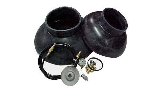
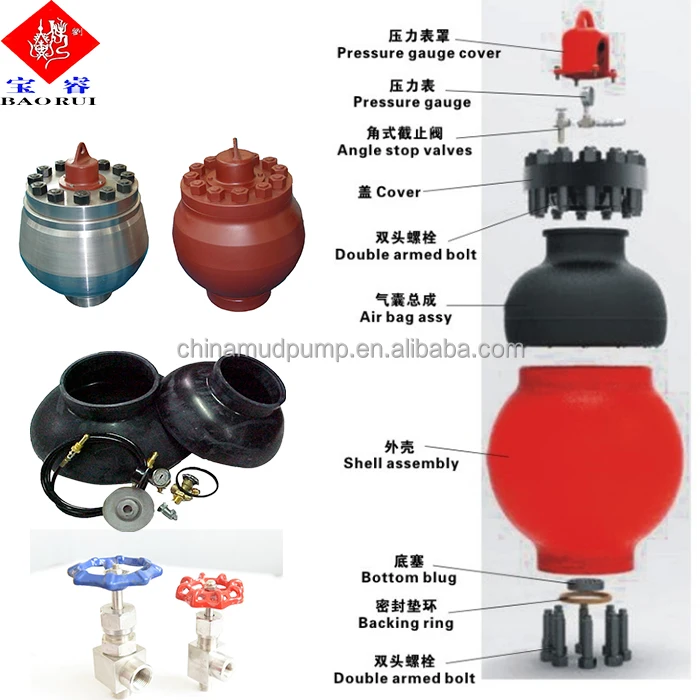
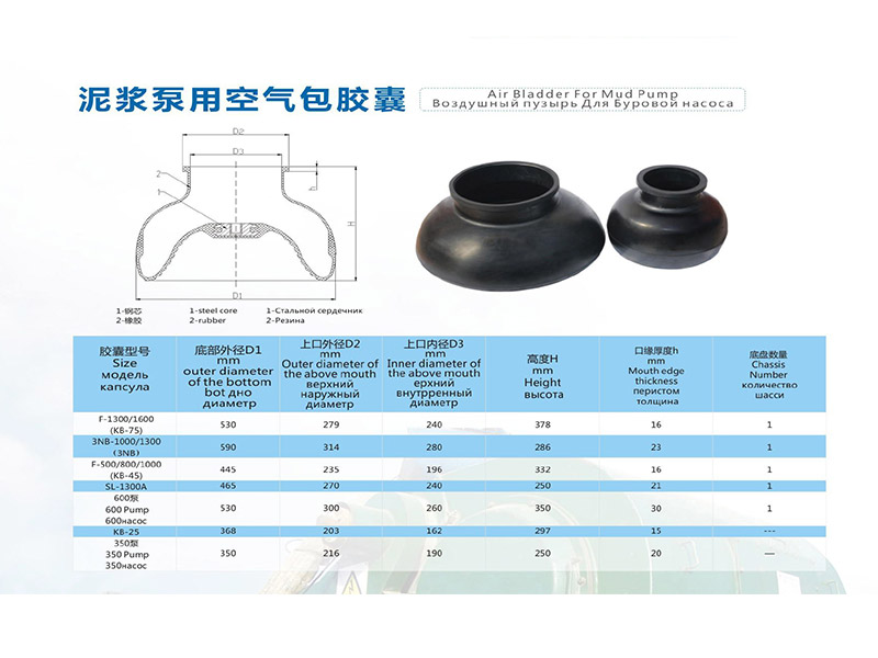
In order to reduce the fluctuation of pressure and displacement of the drilling mud pump, air bag are usually installed on the discharge line. The air bag manufactured by our company has advanced structure and reliable performance, which can make the mud pump achieve the best inhalation effect and is widely used in petroleum, high-pressure pipeline of chemical transportation. This product can also be used as a stabilizer and shock absorber for air extractors.
The pulsation dampener can be divided into discharge pulsation dampener and Suction Dampener.Discharge pulsation dampener- reduces displacement of pump and fluctuation of pressure.
In order to reduce the pressure and displacement of drilling mud pumps, air bags are usually installed on the discharge pipeline. The suction air bags produced by our company have advanced structure and reliable performance, which can make the mud pump achieve the best suction. The effect is widely used in high-pressure pipelines for petroleum and chemical transportation. It can balance the peak pressure of high-pressure fluid in mud pumps, stabilize the pressure, and reduce losses. This product can also be used as a stabilizer and shock absorber for air extractors.
The mud pump is installed on the discharge line, which can balance the peak pressure of the high pressure fluid of the mud pump, play a role in stabilizing the pressure, reducing losses and ensuring safety, so that the mud pump can achieve the best suction effect.
Drain buffer: Installed at the drain end of pumps and compressors, it can avoid fatigue damage of cylinder pistons, valves, bases and pipelines due to pressure fluctuations, thereby extending the service life of the equipment.
Absorption of oscillation: The opening of the valve in the fluid system and the sudden closing of the valve for various other reasons will cause a huge impact pressure to form a water hammer phenomenon, causing the rupture of the pipe and the pipe seat and the damage to the downstream equipment. After installing the suction air bag, it can act as a buffer to avoid this phenomenon.
Reverse Oscillation: When the head of the water pump reaches a certain height, the reverse oscillation caused by the impact of the fluid into the pump valve will cause the pump to suddenly shut down. A suction air bag is installed to absorb part of the vibration.
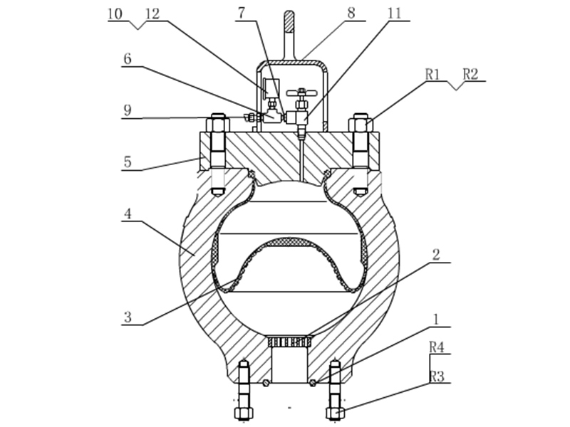
The pulsation dampeners shall be installed properly to reduce the pressure fluctuation and smooth the liquid flow. In order to extend the lifespan of the air bag, it is highly recommended to maintain the suggested proportion of the pump pressure to the pre-charge pressure of the air bag for the pulsation dampeners. Generally, the pump pressure shall be 2/3 that of the discharge pressure and no more than 4.5MPa.
2. During maintenance, the pump pressure and the pressure inside the pulsation dampeners shall be zero. Since the residual pressure is generally small and can not be indicated on the pressure gauge, user shall confirm the pressure carefully to avoid accident caused by low pressure.
For both onshore and offshore drilling applications, American Block’s pulsation dampeners are manufactured and hydro-tested by our legacy in-house team of experts. These dampeners are designed to meet the most demanding large-volume and high-slurry pump applications and provide ease of installation and elongated service life for the Operator.
Mud Pump Pulsation Dampener is usually installed on the discharge line to reduce the fluctuation of pressure and displacement of the drilling mud pump.
Mud Pump Pulsation Dampener is a pneumatic device built into the outflow line of each UUD pump to dampen the pressure fluctuations resulting from the action of the pump. Although presented as a surge tank, this device is really a device that can be tuned to greatly diminish the output pulsations transmitted downstream from the mud pump. Unfortunately, the effectiveness of the pulsation dampener is a function of both output pump pressure and frequency of the pump pulsations.

A pulsation dampener reduces or eliminates the variations in pressure and flow produced by reciprocating pumps. In many applications, low frequency pressure waves cause problems within a given piping system and/or process. Eccentric, cam-driven pumps are probably the most commonly applied for services that require pulsation dampening, e.g., metering pumps and reciprocating (power) pumps.
Pulsation dampeners are found in a variety of designs, but for our purposes we will focus on only gas-charged pulsation dampeners, which rely on a calculated volume of compressed gas, usually Nitrogen, which is alternately compressed and expanded in synchronization with the pump plunger to reduce or eliminate pressure pulsations. This gas volume is normally separated from the process fluid by a flexible membrane. Common membrane designs include elastomeric bladders, PTFE diaphragms, PTFE bellows or stainless steel bellows.
Pressure waves or pulses are a consequence of the alternating acceleration and deceleration of fluid velocity corresponding to the travel of the piston or plunger. The pattern and amplitude of these pulses varies with pump configuration, specifically the number and size of pistons, as well as fluid compressibility factors.
It is precisely the fluid volume above mean on the discharge cycle of each stroke, which induces these pressure pulsations into a piping system. The number of pistons offered by the pump—given that all are of identical diameter and equally phased—displace a known peak volume above mean. These constants may be influenced by fluid compressibility, but for the purpose of this explanation we’ll assume none at this point. A pulsation dampener absorbs only that portion of piston displacement above mean flow, and then stores it momentarily before discharging it during the portion of the cycle below mean flow (on the suction stroke).
A simplex pump displaces a volume of fluid above mean that is equal to about 60 percent of total displacement. A duplex pump displaces a lower fluid volume above mean, approximately half that of a simplex pump. Pumps of three or more pistons of equal diameter, stroke length and proportionally phased will always present a very small fluid volume above mean to the piping system. A triplex pump, for example, produces about a 4 percent peak, as long as fluid compressibility factors and pump efficiencies are not at issue.
These smaller fluid volumes are accounted for by the crank angle of each of the cylinders. Triplex pumps are offset by 120-deg. Quadruplex pumps are set apart at 90-deg offsets; quintuplex pumps are offset 72-deg, and so on. It is the resulting overlap in pulses that yield the smaller fluid volumes above mean.
Fluid velocity gradients follow the same mechanical velocity gradients of the eccentric cam that drives the piston(s). Halfway through the piston’s forward travel (discharge stroke), fluid velocity between the discharge check valve and the pulsation dampener begins to decay. The corresponding drop in pressure causes the membrane inside the dampener to expand since the internal gas pre-charge pressure is now higher than the line pressure. The (stored) fluid now being displaced by the pulsation dampener maintains velocity downstream of the dampener thereby reducing, if not eliminating, any downstream pulsations.
Note: A pulsation dampener removes pulses only from the line downstream of the dampener—not upstream. That’s why it’s always recommended that discharge dampeners be installed as close to pump discharge nozzles as possible. In an application of a dampener for suction stabilization (reduction of acceleration head losses), it is the velocity gradient between the supply vessel and the suction nozzle that is minimized.
Let’s begin by defining the pump details required to properly size a pulsation dampener. We will use these values in a sample calculation to help clarify the process.
We recommend that the gas pre-charge pressure be set to 80 percent of system pressure. Lower pre-charge pressures may be specified elsewhere, but our experiences show that this is a low enough pressure to allow the membrane to move freely during operation while maximizing the gas volume. We will use 0.80 in the formula as the “% Pre-Charge” for 80 percent.
The result of the previous calculation is then divided by a constant. As noted previously, the constant is a function of pump configuration. We use a conservative 1.5 for simplex pumps, 2 for duplex pumps, and 7 for triplex pumps. Remember—if the fluid is compressible, then the constant may have to be adjusted downward.
Fluid volumes above mean are well within the range of these constants. The fluid pulse above mean flow from a simplex pump, for example, is about 60 percent. When we divide full stroke displacement by 1.5 the result is a conservative 67 percent. The divisor 7 that we use for triplex pumps allows for a nominal 14 percent fluid volume above mean. While 14 percent is far above the actual 4 percent produced by triplex pumps, the higher volume is an allowance for practical reasons, specifically size and nozzle limits. Otherwise, the result would be a very small dampener relative to pump size.
Ranges of (process) temperature and pressure must be considered in any sizing calculations for pulsation dampeners. Compensations must be made for temperature variations, which affect gas density, and dynamic variations in system pressure, since sizing is based on a set pre-charge pressure.
The objective is to select a dampener that is adequately sized to handle a range of operating pressures with a single pre-charge pressure. Remember that the gas pre-charge pressure should always be based on the minimum operating pressure as the pulsation dampener will have no effect when the system pressure is below the pre-charge pressure.
In instances of either (or both) temperature and pressure variation, we compensate by multiplying the result of our original calculation by the ratio of minimum and maximum temperature and pressure extremes.
Changes in ambient temperature can also influence gas density, but they’re generally disregarded for the purposes of pulsation dampener sizing. It is usually sufficient to make seasonal adjustments to pre-charge pressures, if necessary. Temperature and pressure calculations are recommended to be done using absolute values (Kelvin for temperature and BarA or PSIA for pressure).
Some fluids are highly compressible, such as cryogenics, olefins, liquefied gases, anhydrous ammonia, etc. In these instances, the benefit of lower pulsations from multiple piston pumps may be somewhat compromised. Fluid compression occurs during the leading edge of the (eccentric) crank angle. Given sufficient pressure and a high enough compressibility factor, there may be little or no overlap of pulses at all—in which case, adjustments have to be made and pulsation dampeners with larger gas volumes should be selected.
By installing a properly-sized pulsation dampener, users can reduce or eliminate pipe shake, vibration and noise. The result is a continuous flow of product which is required in many metering, mixing and spraying applications. Reduced pressure pulsations minimize long-term damage to instrumentation and pump components while improving the accuracy of many flowmeters and increasing pump efficiency.

Pulsation problems often start on the suction side. Pulsation or cavitation is caused by the variation of fluid movement within a contained system. Since fluid is non-compressible, the energy produced by this pulsation or cavitation must be compensated for. With the introduction of pulsation equipment into a system this energy now has a place to expend itself. Without the pulsation equipment involved in your pumping system, the pulsation or cavitation that is present can lead to the following:

Pulsation is a vibration or throbbing deviation from a steady stream in the flow of water is measured in psi as the range between the lowest and highest pressures achieved in the pulsation cycle.
A pump pulsation dampener has a set pre-charged, gas-filled cylinder with a diaphragm that absorbs system shocks and minimizing pulsations, pipe vibrations, water hammering and pressure fluctuations. By minimizing pulsation in the system components like check valves, packings, and other pump components, your system will endure much less wear and tear. Shop for the accumulator tanks and pump pulsation dampener pressure parts you need at EnviroSpec.

The Pulsation Dampener 3375-0015-3 from the Hypro series assures smooth discharge from piston and plunger pumps. It also reduces peak loading on pump bearings and other internal parts. The Pulsation Dampener 3375-0015-3 extends the system life and minimizes maintenance costs.
As a general guideline, when using two cylinder or four cylinder piston pumps, the dampener charge should be approximantely 1/2 of the pump operating pressure. When using a three or six cylinder pump, te dampener charge should be approximately 2/3 of the pump operating pressure. This pump is rated for up to 1500 psi.

The pulsation dampeners shall be installed properly to reduce the pressure fluctuation and smooth the liquid flow. In order to extend the lifespan of the air bag, it is highly recommended to maintain the suggested proportion of the pump pressure to the pre-charge pressure of the air bag for the pulsation dampeners. Generally, the pump pressure shall be 2/3 that of the discharge pressure and no more than 4.5MPa.
2. During maintenance, the pump pressure and the pressure inside the pulsation dampeners shall be zero. Since the residual pressure is generally small and can not be indicated on the pressure gauge, user shall confirm the pressure carefully to avoid accident caused by low pressure.


 8613371530291