
mud pump valves pistons and liners free sample
Explore a wide variety of mud pump valves on Alibaba.com and enjoy exquisite deals. The machines help maintain drilling mud circulation throughout the project. There are many models and brands available, each with outstanding value. These mud pump valves are efficient, durable, and completely waterproof. They are designed to lift water and mud with efficiency without using much energy or taking a lot of space.
The primary advantage of these mud pump valves is that they can raise water from greater depths. With the fast-changing technology, purchase machines that come with the best technology for optimum results. They should be well adapted to the overall configuration of the installation to perform various operations. Hence, quality products are needed for more efficiency and enjoyment of the machines" full life expectancy.
Alibaba.com offers a wide selection of products with innovative features. The products are designed for a wide range of flow rates that differ by brand. They provide cost-effective options catering to different consumer needs. When choosing the right mud pump valves for the drilling project, consider factors such as size, shape, and machine cost. More powerful tools are needed when dealing with large projects such as agriculture or irrigation.
Alibaba.com provides a wide range of mud pump valves to suit different tastes and budgets. The site has a large assortment of products from major suppliers on the market. The products are made of durable materials to avoid corrosion and premature wear during operations. The range of products and brands on the site assures quality and good value for money.

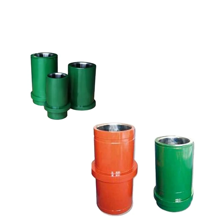
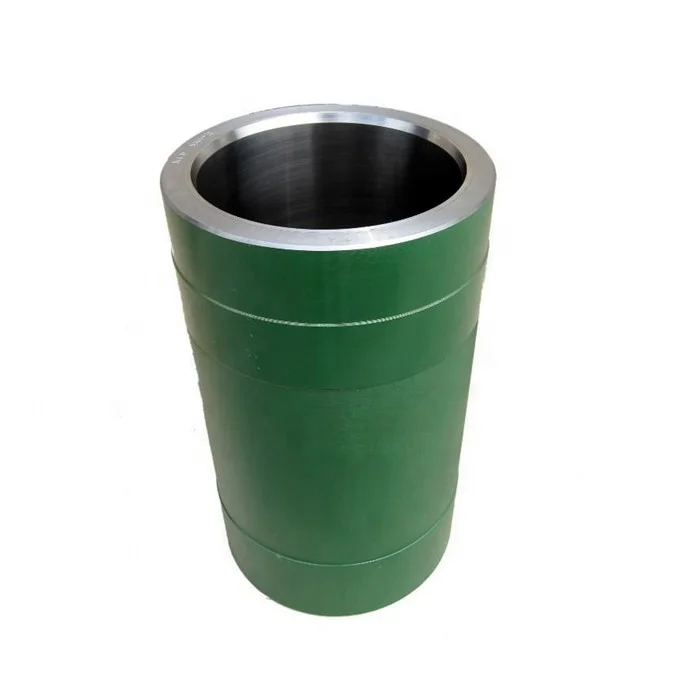
Mud pump is the "heart" of oil drilling system while mud pump liner an important disposable quick-wearing part of the fluid end. Therefore, the quality of mud pump liner will directly affect the normal operation of the drilling rig and thus the drilling costs.
Bi-metal liner is one of the most widely used types of liner. Our product combines the virtue of high strength forged steel shell and the advantage of anti-abrasive corrosion-resistant high-chromium sleeve together. The shell, including lip sleeve, is forged with high-quality carbon steel. The inner sleeve made of high-chromium cast iron is processed by centrifugal casting, the hardness of which is up to HRC 62 after heat treatment, could withstand a mud pressure of 7000 psi.
Ceramic liner is applied to well drilling operations for deep reservoir and complicated geologic situations, and is also used for offshore oil and gas development. The hardness of the working surface of the inner sleeve can reach HRC89 or more while the bending strength can be up to 1000-1200Mpa. Our ceramic liner is able to withstand a maximum pump pressure of 70Mpa. It is anti-abrasive, corrosion-resistant, heat-resistant, pressure-resistance, and is of high strength and high rigidity.
Piston assembly is one of the main parts of the fluid end of the mud pump. The volume of the working chamber alters with the reciprocating of piston, and thus realize a liquid suction and discharge through the pump valve. We are able to provide superior replaceable rubber piston and bonded piston.
Piston assembly, as a vulnerable part, is mainly composed of piston hub, rubber etc. Forged with alloy steel according to strict processing control and heat treatment, the piston hub is of high strength and rigidity, and of long lifespan. In addition, there are several selections for piston rubber under different operating conditions, like Nitrile Rubber, Polyurethane (PU) and Hydrogenated Nitrile (HNBR) etc.
Piston assembly, as a vulnerable part, is mainly composed of piston hub, rubber etc. Forged with alloy steel according to strict processing control and heat treatment, the piston hub is of high strength and rigidity, and of long lifespan. In addition, there are several selections for piston rubber under different operating conditions, like Nitrile Rubber, Polyurethane (PU) and Hydrogenated Nitrile (HNBR) etc.
Valve and seat make up a valve assembly that is the major component of the fluid end of the mud pump. It is also one of the most consumed vulnerable part during drilling.
Valve assembly is made of high-quality forged alloy steel. It has an enhanced strength by a process of carbonization at the working surface. Through precise calculation and advanced NC machining, our product can realize a favorable match between the valve body and the seat. Moreover, material is selectable as per different working situations. Thus, the lifespan of the product can be prolonged.
Valve assembly is made of high-quality forged alloy steel. It has an enhanced strength by a process of carbonization at the working surface. Through precise calculation and advanced NC machining, our product can realize a favorable match between the valve body and the seat. Moreover, material is selectable as per different working situations. Thus, the lifespan of the product can be prolonged.

This website is using a security service to protect itself from online attacks. The action you just performed triggered the security solution. There are several actions that could trigger this block including submitting a certain word or phrase, a SQL command or malformed data.

This website is using a security service to protect itself from online attacks. The action you just performed triggered the security solution. There are several actions that could trigger this block including submitting a certain word or phrase, a SQL command or malformed data.
Full-Open Valves . . . . . . . . . . . . . . . . . . . . . . . . . . . . . . . . . . . . . . . . . . . . . . . . . . . . . . . . . . . . . . . . . . . . . . 3
Chrome-Iron Liners . . . . . . . . . . . . . . . . . . . . . . . . . . . . . . . . . . . . . . . . . . . . . . . . . . . . . . . . . . . . . . . . . . . 6
Zirconia-Ceramic Liners . . . . . . . . . . . . . . . . . . . . . . . . . . . . . . . . . . . . . . . . . . . . . . . . . . . . . . . . . . . . . . . 7
Bonded-Nitrile Pistons . . . . . . . . . . . . . . . . . . . . . . . . . . . . . . . . . . . . . . . . . . . . . . . . . . . . . . . . . . . . . . . . . 9
Replaceable Nitrile Pistons . . . . . . . . . . . . . . . . . . . . . . . . . . . . . . . . . . . . . . . . . . . . . . . . . . . . . . . . . . . . 10
Mud-Pump Gear Sets . . . . . . . . . . . . . . . . . . . . . . . . . . . . . . . . . . . . . . . . . . . . . . . . . . . . . . . . . . . . . . . . . 13
Service and Support . . . . . . . . . . . . . . . . . . . . . . . . . . . . . . . . . . . . . . . . . . . . . . . . . . . . . . . . . . . . . . . . . . 16
Weatherford products and services are subject to the Company’s standard terms and conditions, available on request or at weatherford.com. For more information contact an authorized Weatherford representative. Unless noted
otherwise, trademarks and service marks herein are the property of Weatherford. Specifications are subject to change without notice. Weatherford sells its products and services in accordance with the terms and conditions set

The invention relates to an assembly for quickly securing and releasing a component to a pump housing and more particularly to a retainer assembly for releasably mounting a piston liner within a hydraulic cylinder on the module of a pump.
Heavy duty large horsepower pumps are used to pump fluids or slurries with entrained solids. In the oil industry, for example, slush or mud pumps are used to pump viscous fluids, such as drilling muds, cement, or other well fluids. Although mud pumps may be either centrifugal or reciprocating type pumps, typically mud pumps are reciprocating pumps using one or more pistons and hydraulic cylinders with liners to generate the high pressures required to pump these viscous fluids in and out of the well.
Mud pumps include a fluid end and a power end. In the fluid end of one type of a triplex mud pump, for example, there are three sets of suction modules and discharge modules in fluid communication. A suction manifold is connected to the fluid inlets of the suction modules for receiving fluids and passing those fluids to each of the suction modules. A discharge manifold is connected to the fluid outlets of the discharge modules for discharging the pumped fluids. Each module encloses a set of flow passages with check valves for controlling the direction of flow of the fluids. A check valve is disposed at the suction module fluid inlet to only allow fluids to enter the suction module inlet end of the module and another check valve is disposed at the discharge module fluid outlet to only allow fluids to exit the the discharge module for flow into the discharge manifold.
Each discharge module includes a liner retainer flange attached to the discharge module. The liner retainer flange attaches to a replaceable liner within which a pump piston reciprocates. The piston is a generally cylindrical steel member having a polymer, such as polyurethane, bonded to its outer diameter for sealingly engaging the inner cylindrical wall of the liner to ensure a fluid tight seal required for drawing the low pressure fluids through the suction manifold and module flow passages. The seal integrity must be maintained to withstand the high discharge pressure on the discharge stroke. The power end contains the gears that reciprocate the pump piston within the liner for pumping the fluid through the module passages in the fluid end and thence out the discharge valve.
In operation, on the suction stroke, the pump piston draws fluids through the suction manifold and suction valve as the piston strokes within the liner. On the discharge stroke, the check valve in the discharge module opens simultaneously as the suction valve closes preventing suction back flow into the suction module. Fluid in the liner is compressed and pressure is built up until the pressure overcomes well bore pressure so as to pump the mud into the well. The piston then reverses for another suction stroke whereby the check valve in the suction module opens and the discharge valve closes simultaneously, the piston now making a suction stroke.
As the piston reciprocates within the liner, friction wears the liner. Further, the fluid passing through the fluid end includes particulates and other solids which wear away and destroy the liner and piston. When the liner and piston degrade, the fluid seal is lost and the pump becomes much less efficient. Also, the reciprocation of the piston in the liner causes pulsations that over time cause the liner to become loose within the containment of the liner retainer flange thus resulting in a degradation of the seal at the face of the liner and the seal at the face of the liner wear plate. Therefore, it is important to be able to replace the liner as a part of routine maintenance (or when emergencies occur from seal failure while drilling) to ensure that the pump operates efficiently and can control well pressure. It is also important to have a means for fastening the liner to the liner retainer flange so as to ensure that the liner remains firmly secured despite extended reciprocation of the piston assembly within the liner.
Typically each liner retainer flange, and the cradle of the pump power end are all secured to the fluid end module by studs and threaded connections. Because of the environment in which the mud pump operates and the corrosive nature of the fluids being pumped, the studs and threaded connections, such as nuts, become corroded and are difficult to unthread for the replacement of the liner. Often, the threaded connections have been over tightened, making it even more difficult to unthread. Where the liner is retained by an end cap, a steel bar is inserted into a guide hole in the side of the end cap and then the cap is unscrewed using a significant amount of torque. This end cap is very heavy as it must have sufficient strength to keep the liner from moving, even with pressures up to 7500 psi. Where a nut or end cap resists unscrewing, a sledge hammer is used to hammer on a socket wrench or a special hammer wrench is used to loosen the nut or cap. Such activity is obviously dangerous. In some regions of the world local laws prohibit the use of sledge hammers for personnel safety reasons or to avoid the risk of an explosion due to sparks.
Prior art liner retention systems include spring mechanisms around each stud with an end flange for securing the liner against a fluid end module. Hydraulic pressure is applied to the spring mechanism of each stud by a small hydraulic pump to remove the clamping force of the spring mechanism. The release of the clamping force allows the removal of the clamping flange of the liner retention system. Individually actuated spring loaded studs cause an uneven pressure to be applied to the clamping flange. Further, the clamping force is limited because of the limited space available to hold numerous springs.
The liner retainer assembly of the present invention includes a liner retainer flange that is mounted on the discharge module of the fluid end of a pump. A pressure actuated hydraulic clamping piston with related actuated, conical dished washers and necessary static and sliding seals is disposed within the retainer flange . The hydraulic pressure actuated clamping piston is configured to receive and hold the liner. The hydraulic clamping piston and an end cap maintain the liner in contact with the module during actuation. The hydraulic clamping cylinder includes a counterbore which is divided by the hydraulic piston into a fluid cavity and a spring cavity. The spring cavity houses a plurality of springs which bias the hydraulic piston, end cap, and liner towards the module, thus providing a strong clamping securing force when the hydraulic pressure is released. The fluid cavity communicates with a supply of hydraulic fluid for biasing the hydraulic piston away from the module to activate the springs. By pressurizing the fluid cavity, the springs are compressed so as to disengage the liner retaining end cap from the liner and allow the unthreading of the liner end cap to then remove the liner.
The liner retainer assembly permits preloading or prestressing of the liner against the module of the fluid end of the pump so that the liner will not loosen upon the reciprocation of the pump piston within the liner. Further, the liner may be easily secured and unsecured from the module without the necessity of a sledge hammer or other methods for applying excessive amounts of torque to a securing fitting. The assembly of the present invention permits the easy and quick replacement of the liner as necessary.
FIG. 2 is a cross-sectional view and partial exploded view of the liner retaining flange assembly of FIG. 1 illustrating the application of hydraulic pressure for the attachment of a retaining cap.
FIG. 3 is a cross-sectional view of the liner retaining flange assembly of FIGS. 1 and 2 following the attachment of the retaining cap prior to energizing the Belleville washers.
Referring first to FIGS. 1 and 2, there is shown a fluid end module 10 and a cradle 28 of the pump power end. The pump is of the type used to pump fluids, such as drilling muds, cement or the like. Pumps of this type are well known. A wear plate 14 defines a bore 16 which leads into liner 20. The module 10 is used for the transfer of fluid from the suction manifold and suction module (not shown) to the discharge manifold (not shown) and discharge module.
An exemplary liner retaining flange assembly 18 of the present invention is used to secure liner 20 within a hydraulic cylinder 30 mounted on module 10 and liner retainer flange 22. Those of skill in the art will understand that a pump piston (not shown) attached to the power end of the pump is reciprocated within the liner 20 to effect the desired pumping action to flow fluid through the fluid end module 10 of the pump. Hydraulic cylinder 30 provides an open end into which the liner 20 is inserted. Module 10 also provides a counterbore 12 for the adjacent wear plate 14 against which it is desired to retain the liner 20 during operation of the pump piston. It can be appreciated that the purpose of wear plate 14 is to avoid the end of liner 20 wearing module 10 due to the reciprocation of the piston within liner 20. However, wear plate 14 may cause wear to the module 10 if the liner 20 is not securely affixed. Wear plate 14 may be replaced should that wear become excessive. It is noted that the end of the liner 20 adjacent the wear plate 14 includes an internal annular groove 59 with seal member 61 for sealingly engaging the wear plate 14 and the other open end 15 of liner 20 includes an external annular load-bearing shoulder 60 which retains end cap 64 (FIG. 2).
The hydraulic cylinder 30 includes a threaded, reduced diameter portion 24 and an enlarged diameter portion 32. Reduced diameter portion 24 is secured in a threaded or splined relation at 23 to liner retainer flange 22 that is located in an abutting relation to the module 10. Bolted studs 26 secure the cradle 28 of the pump power end, the liner retaining flange 22 and hydraulic cylinder 30 to module 10.
The enlarged portion 32 of hydraulic cylinder 30 includes an inner clearance cavity 33 which has a reduced diameter neck, forming a hydraulic cavity 58 to activate hydraulic piston 42 which in turn compresses springs 56 which are restrained from escaping from the spring cavity 35 by retainer ring 48. Hydraulic sealing is accomplished by sealing rings 39 and 49. End cap 64 is held in place with external threads 46. A hydraulic fluid port and fitting 38 is disposed through the wall of enlarged diameter portion 32.
When these components are assembled, the annular flange 44 of piston 42 forms hydraulic cavity 58 and outer spring cavity 35. The hydraulic fluid port and fitting 38 communicates with hydraulic cavity 58 for applying hydraulic pressure to flange 44. The spring cavity 35 houses a plurality of axially compressible Belleville springs or washers 56. Retainer ring 48 has external threads 50 which threadingly mate in a complimentary fashion with the internal threads 34 of enlarged diameter portion 32. The washers 56 bear against the retainer ring 48 and annular flange 44. Enough springs are used so as to insure sufficient force is generated to prevent movement of liner 20 when pump pressure is at maximum. The retainer ring 48 secures the washers 56 and hydraulic piston 42 within the enlarged diameter portion 32 of hydraulic cylinder 30. O-ring 49 provides a fluid-tight seal between the piston 42 and enlarged diameter portion 32.
Upon assembly as shown in FIG. 1, hydraulic piston 42 has previously been inserted into enlarged diameter portion 32 of cylinder 30 to form cavities 58 and 35. Belleville washers 56 are inserted into outer spring cavity 35 and retainer ring 48 is threaded into place. The liner 20 is inserted into the outer hydraulic cylinder 30 of liner retaining assembly 18 so that the end of the liner 20 with seal 61 abuts wear plate 14.
Referring particularly to FIG. 2, the retaining assembly 18 is shown ready to secure the liner 20 in place. A hydraulic hose 62 is secured to the external port and fitting 38 for supplying hydraulic fluid to inner hydraulic cavity 58. As fluid pressure is supplied to cavity 58, fluid pressure is exerted against flange 44 urging piston 42 outward toward retainer ring 48. As annular flange 44 of piston 42 is so moved, springs 56 are axially compressed. As springs 56 are compressed, the threaded end 46 of piston 42 extends further away from wear plate 14 and module 10.
In the outward and extended position of piston 42, end cap 64 is threaded onto the threaded end 46 of the piston 42 so the threads 46 mate with the threads 66 of end cap 64. End cap 64 need only be hand tightened. It is noted that liner load bearing shoulder 60 mates with the shoulder 68 on end cap 64.
Referring now to FIG. 3, the retaining assembly 18 is shown completely assembled with the liner 20 securely affixed within the hydraulic cylinder 30. Once end cap 64 has been affixed, the fluid within the hydraulic cavity 58 is evacuated through port and fitting 38 permitting the springs 56 to bias flange 44 toward wear plate 14 and module 10 and bias end cap 64 against the other end 15 of liner 20. As the hydraulic pressure in the hydraulic cavity 58 is released, stored energy from the compression of springs 56 is released to load the liner 20 longitudinally. As a result, the energy stored by compressing springs 56 is transmitted to the liner 20 in order to load it longitudinally against wear plate 14 and module 10.
In order to remove the liner 20, the procedure is substantially reversed. Fluid is introduced into the hydraulic cavity 58 through port and fitting 38 in the same manner as previously described to compress springs 56 and external piston 42. Once spring forces are removed, end cap 64 may then be unthreaded. Fluid is bled off, springs 56 are decompressed and the unit is stabilized.
It is noted that the arrangement of the present invention permits a liner to be replaced rapidly and easily and without the use of extra tools or having to apply excessive torque. Further, a prestress force is applied to the liner 20 so that it is longitudinally compressed against wear plate 14 and module 10. This load or prestress securely holds the liner 20 against the wear plate 14 despite repeated reciprocation of the pump piston within liner 20.
Referring now to FIGS. 4 and 5, an alternative embodiment for an exemplary retaining assembly 70 is illustrated with the liner 20 inserted and securely affixed therewithin. For simplicity, like reference numerals are used for like or similar components. FIG. 5 is a cross-sectional view of the hydraulic cylinder 36 taken along plane V--V in FIG. 4.
In this embodiment, hydraulic cylinder 36 defines a plurality of individual piston chambers 72. There are 4, 6, or 8 chambers 72 (depending on the holding force required) which are azimuthally spaced around hydraulic cylinder 36. Each piston chamber 72 contains a wear cylinder sleeve 101 with an individual piston 74 that is reciprocably disposed therein. Wear sleeve 101 includes threaded bores 103 for receiving bolts to assist in the replacement of sleeves 101 when excessive wear has occurred. Each piston 74 provides an elongated shaft 76 and a radially extending flange 78 so that when disposed within the chamber 72, the chamber 72 is divided into a spring retaining chamber 80 and fluid chamber 82. The shaft 76 of the piston 74 is threaded at 84 for threadingly receiving a nut 86. Fluid may be introduced into the fluid chamber 82 through an associated hydraulic fluid port and external fitting 38.
Referring particularly to FIG. 5, a plurality of fluid passages 106 are provided in hydraulic cylinder 36 which interconnect and communicate with each piston chamber 72 and each of the ports and fittings 38 on the hydraulic cylinder 36. The fluid interconnection permits all of the fluid chambers 82 (FIG. 4) to be filled with fluid by using only one or a few of the hydraulic fluid ports and fittings 38 for injecting fluid. The common communication with all fluid chambers 82 also allows the common hydraulic actuation of all the pistons 74 (FIG. 4).
In operation as shown in FIG. 4, the liner 20 is installed and removed in a manner similar to that described with respect to liner retaining assembly 18. Fluid is introduced into each individual fluid chamber 82 urging the associated piston 74 to move toward the open end 15 of liner 20. Energy is stored through axial compression of the Belleville springs 94. The end cap 98 is placed onto the liner open end 15 so that the shoulder 104 engages shoulder 60 of liner 20. Nuts 86 are then tightened onto each piston 74. Again, the nuts need only be hand tightened. Fluid is then evacuated from the fluid chambers 82 and the Belleville springs 94 bias pistons 74 toward the wear plate 14 and the module 10, thus loading liner 20 longitudinally against wear plate 14 and module 10.
While preferred embodiments of this invention have been shown and described, modifications thereof can be made by one skilled in the art without departing from the spirit or teaching of this invention. The embodiments described herein are exemplary only and are not limiting. Many variations and modifications of the system and apparatus are possible and are within the scope of the invention. Accordingly, the scope of protection is not limited to the embodiments described herein, but is only limited by the claims that follow, the scope of which shall include all equivalents of the subject matter of the claims.

Mystique Mud pump Coolant and Lubricant extends mud pump liner and piston life and provides internal lubrication and extra cooling to the coolant system of mud pumps. It extends the life of all liners, even ceramic. Mystique will not cause corrosion or rusting of iron, and is safe with all alloys. Recommened dilution rate of 12.5%. (25 gallons will treat a 200-gallon system.) For use on closed systems.

AN OPERATIONAL SAFETY RELIEF VALVE MUST BE INSTALLED IN THE DISCHARGE LINE BETWEEN PUMP AND ANY OTHER PIPE FITTINGS. THIS RELIEF VALVE MUST BE SET AT THE RECOMMENDED RELIEF PRESSURE DESIGNATED ON THE PUMP APPLICATION TAG. CATASTROPHIC DESTRUCTION OF PUMP, PIPING, OR PERSONAL INJURY MAY RESULT IF DISCHARGE LINES ARE CLOSED WHEN THE PUMP IS STARTED, OR AFTER THE PUMP IS RUNNING.
Gears, connecting rod bearings and crossheads in all geared piston type pumps are lubricated by splash from lubricant in the crankcase. Crankshaft bearings and pinion shaft bearings in series 1800, 1500, 1600, 1700, 1900, and 2600 pumps are also lubricated from this same oil in the crankcase by splash. Shaft bearings in Series 1550-C, 1654-C, 2000 and 2200 pumps and in pumps with Serial Number 24523 and below are sealed off from the crankcase lubricant by oil seals and run in a separate bath of oil retained in the respective bearing housing.
WARNING -The crankcase is drained after testing pump at the factory. Remove crankcase cover or crosshead guide hand hole cover and fill with sufficient lubricant before starting the pump for the first time.
Quantity and type of lubricant required to fill crankcase to proper level is shown below. For chain and sprocket driven pumps use an SAE 30 high grade mineral oil in Crankcase.
For herringbone gear driven pumps operating in average climates, use SAE 90EP, AGMA 5EP, or AGMA 6EP gear lubricants. Be sure, however, to use an EP lubricant that will not have a corrosive action on Bronze and that it contains rust, oxidation and foam inhibitors. multi-purpose multi-viscosity gear lubricants are UNSATISFACTORY for use in GASO pumps.
For worm driven pumps, use an SAE 140 EP Gear Lubricant. Running temperature of crankcase oil should not exceed 180 degrees Fahrenheit. If higher temperatures occur and mechanical fits are found to be correct the use of a separate oil cooler is recommended. In addition, SAE EP 140 Gear Lubricant should be placed in separate bath bearings on pump where they are standard.
Check oil level and appearance daily. Change oil and clean breather every six months or 2000 hours running time, more often under severe operating conditions. The crankcase should be thoroughly cleaned at each oil change. Contamination of the oil by saltwater will be indicated in only a few hours by the oil turning white, milky, or foamy. Contamination of the oil by moisture condensation will be indicated by the oil slowly turning dark or a rusty brown. Whenever any type of contamination or dilution is detected, drain the crankcase, remove the crankcase cover and crosshead guide hand hole cover, thoroughly flush out the oil and refill with clean oil as necessary to bring to full mark on the dipstick. Do not overfill. At the same time, check and clean breather. oil lost by leakage should be replaced before the level becomes too low. If loss is excessive, check the packing in the crankcase stuffing boxes, the oil retainer on the pinion shaft, and clean the crankcase breather.
LUBRICATION OF SHAFT BEARINGS IN SERIES 1550-C, 16540C, 2000 and 2200 - (AND FOR PUMPS #24523 AND BELOW) These pumps are equipped with inner oil seals on pinion shaft and crankshaft, so they run in a separate bath of SAE EP 90 Gear Lubricant or SAE 50 high grade motor oil or mineral oil. The correct amount of oil is put into the bearing housings when pump is shipped from factory, but a check should be made to see that none has leaked out or been removed. Proper oil level is even with pipe plug in lower part of bearing housing flange or cover plate.
Inspection should be made regularly to determine if any loss has occurred by leakage past the oil seals. If necessary add oil through plugged hole in top of bearing housing flange. Do not fill above ""oil level"" as too much oil will churn and create excessive heat. Remove cover plates, flush with kerosene, inspect bearings, and refill with clean oil at least once every six months.
Pumps with herringbone gears #24523 and up do not have inner oil seals installed for the pinion and crankshaft bearings as standard equipment however, you pump may have these seals installed as special equipment. if your pump has inner oil seals installed, the amount of oil required for the crankcase is as follows:
Inspect connecting rod bearings and adjust as necessary every six months or when crankcase lubricant is changed. The bearings in the crank end are babbitt lined steel shells, adjustable for wear by removing shims and easily replaced when completely worn. These bearings should be watched closely and adjusted to compensate for wear. You will note that shims do not completely fill the outer gap between rod and cap casting although the connecting rod bolts are tight. This is because the faces of the shell bearings project slightly beyond the faces of the rod and cap castings and the shims are gripped only between the faces of the bearing halves. Do not try to close this outer gap by tightening the connecting rod bolt as it will put an excessive strain on them.
To check for wear, place a wrench on the top connecting rod bolt and shake the rod parallel to the crankshaft. (The pressure must be relieved from the liquid end of the pump so that the pump"s mechanism is free to move.) If the rod bearing moves without resistance, the bearing may be too loose and need adjusting. If the bearing does need adjusting, remove shims until you cannot shake the rod, then add .005"" shims one at a time until there is a little side movement. Be sure to torque rod bolt nuts to proper value for each adjustment. (NOTE: If you are making this adjustment after having had the crossheads out, be sure that the oil holes in the rod are pointing up. The ""up"" side is indicated by matching numbers stamped on the cap and rod at the split between them. These numbers should be the same on each rod and should be on the top side of the crankshaft.) Turn the shaft by hand and if there is any hard drag or tight spots in the bearing, add another .005"" shim. After this bearing is properly adjusted, loosen bolts a few turns and repeat the above operation on the other bearings. After all bearings have been adjusted, torque all connecting rod bolt nuts back to proper amount. Again turn the pump by hand to check for excessive drag and tight spots. If none, the pump should then be ready for operation.
If the pump cannot be rotated by hand due to the drive being enclosed, the bearings may be completely adjusted by shaking the bearing on the shaft as stated above. Care must be taken not to over-tighten the bearings since they cannot be checked by rotating the pump by hand. When bearings are adjusted by this method, they must be watched carefully for overheating when the pump is put into operation.
Alternatively, plastic gauge strips, found in most parts stores may be used to adjust these bearings. It is usually better to have a bearing a little too loose than too tight. A slightly loose bearing will cause very little trouble because of the slow operating speeds of the pump, but a tight bearing will overheat and the babbitt may melt or pull. with experience, an operator can tell by feel when the bearings are properly adjusted. Normal precautions must be taken to insure cleanliness of parts upon their assembly. All wrenches used in adjusting these bearings are standard wrenches.
Bearings in the crosshead end are bronze bushings. To replace these bushings, remove connecting rod and crosshead assembly from pump. Press out the crosshead pin, and then remove and replace bushing. After the new bushing has been pressed into the connecting rod, it should be reamed for a loose fit on the crosshead pin as follows: .002"" for pumps Series 1500, 1800, and 1700, .0025"" for pumps Series 1600, and .004"" for pumps Series 2600.
Crankshaft bearings are single tapered roller bearings and are splash-lubricated from oil in the crankcase. These should be flushed clean and carefully inspected and adjusted as necessary at least once every six months, or whenever crankcase lubricant is changed.
Crankcase bearings for Series 1800, 1500, 1600, and 1700 pumps should have an end play in the crankshaft of: .001"" to .003"" for 1800 pumps .002"" to .004"" for 1500 pumps & 1600 pumps .003"" to .005"" for 1700 pumps
This end play is measured when pump is cold to allow for expansion due to heat under operating conditions. Bearings may be adjusted from one side only. To adjust bearings for end play, disconnect connecting rods, remove several shims (more than necessary) from under the bearing housing, tighten up on crankshaft bearing housings until bearings bind slightly when shaft is rotated by hand. Then measure the shim gap with a feeler gauge and add its equivalent plus from .001"" to .003"" of shim (for normal clearance) and tighten up on crankshaft bearing housing cap screws.
Crankshaft bearings for series 2600 Pumps have a .012"" to .013"" pre-load. To get this pre-load, try different thicknesses of shims until a slight drag is felt while rolling the shaft and then remove .012"" to .013"" of shims. When necessary to install new bearing cones on crankshaft, heat them in oil at 280 degrees Fahrenheit for easy installation. Be sure they are firmly against the shoulder on the crankshaft.
Please note: Improper application of heat to these bearings during their installation in GASO pumps will automatically revoke the warranty on the bearings. It is suggested that the procedures outlines above be closely followed when changing bearings. PINION SHAFT BEARINGS - The pinion shaft bearings are self-contained ball or roller bearings and have no adjustment for wear. Their load ratings are far above the load applied and will therefore have very little wear if properly lubricated.
he herringbone gears are continuous tooth Sykes design. Pinion gear is alloy steel and keyed to the pinion shaft. Main gear is a high grade semi-steel or ductile iron casting, with internal flange for bolting to crankshaft with cap screws. Gear teeth may show signs of slight pitting after being run awhile, but with proper lubrication this will cease and teeth will smooth up.
Meshing of these herringbone gears provides the principal method of lubricating the pinion and crankshaft bearings. Therefore, the pinion must be turning in the direction specified on the power frame casting and the gears must be meshing so the center part of the gear teeth come together first.
Although pumps may run backwards without adversely affecting operation, always run them faster than 75 strokes per minute or install inner oil seals for pinion shaft and crankshaft bearings.
In worm-driven pumps, the main or ring gear, is of special nickel alloy bronze with internal flange for bolting to center disc of crankshaft. The driving worm and shaft is one piece, of chrome nickel steel, hardened and ground. This worm and shaft is removable through the end of worm case toward the liquid end of pump but it will first be necessary to remove the flexible coupling, stuffing box, and thrust bearing jam nut from other end of shaft. The thrust bearings will slide off when shaft is withdrawn.
To remove crankshaft and main gear, take out cap screws holding oil reservoir half-ring to inner end of main bearing housing, remove bearing housing clamps and pull main bearing housings outward until free of bearings. Then lift crankshaft and gear assembly out. Support crankshaft and gear assembly with a block or hoist before pulling the bearing housings outward.
Series 1550-C and 1654-C pumps use quadruple row internal sprockets with specially made heavy duty quadruple row chain. The driving pinion shaft and sprocket is one piece with Nitride Hardened sprocket teeth.
The main sprocket is of alloy steel, with internal flange for bolting to center disc of crankshaft. To remove crankshaft and main sprocket, pull master link from chain, remove cap screws holding oil seal rings to inner end of main bearing housing, remove bearing housing clamps and pull main bearing housings outward until free of bearings. Then lift crankshaft and gear assembly out. Support crankshaft and sprocket assembly with a block or hoist before pulling the bearing housing outward.
The piston rod stuffing boxes in power end of pump are packed at the factory. The purpose of this packing is to wipe the piston rod clean and thus prevent contamination of lubricant in the crankcase and also to prevent loss of oil from the crankcase. Adjust this packing by evenly tightening the packing gland cap screws until leakage is minimized.
Over a period of time, beginning may, 1978, all liquid end bodies for Duplex Piston Pumps were gradually redesigned to accept an O-ring mounted in a bevel at the opening of the valve covers, cylinder heads and stuffing boxes. This re-design allowed the flange of the valve cover, cylinder head, or stuffing box to fit metal-to-metal with the liquid body. Prior to this re-design most of these liquid ends were counter-bored to accept a flat gasket which caused a gap between the flanges of the valve covers, cylinder head, or stuffing boxes and the liquid end. BEFORE YOU REPAIR YOUR PUMP, MAKE A VISUAL CHECK TO SEE WHAT TYPE OF VALVE COVER, CYLINDER HEAD, AND STUFFING BOXES ARE ON THE PUMP.
The list of serial numbers below will serve as a general guide to the first pumps fitted with o-rings, but does not guarantee that your pump has them. You must check your pump before ordering parts for it. The first number is the pump serial number, the second number is the liquid end serial number:
Liquid end stuffing boxes on a new pump must be packaged by the user before the pump is put into service. The necessary packing will be found in small sacks packed in a box with other pump accessories. Standard packing consists of lip type packing rings. These function best when not squeezed up too tight. Special packing sometimes furnished consists of square graphited duck and rubber packing rings. These require more pressure to seal off fluid satisfactorily, but care should be exercised to avoid over-tightening. Good practice is to let packing leak slightly.
Standard pistons for crude oil service consist of cast iron or steel bodies with special patented cast iron porous chrome faced piston rings. Cast iron or steel piston bodies with nylon glass filled piston rings are furnished pumping crude oil products. Cup type pistons are furnished for pumping saltwater and rubber inserted pistons are used for slush and cementing service.
To replace pistons, remove crosshead jam nuts and power end and liquid end stuffing box glands and packing. Remove cylinder heads and pull rod, piston and liner through front of liquid end. Install new pistons, rings or cups is required. Insert pistons on to rod and into liners, oriented with front of piston toward flange end of liner. Install new liner gasket, and slip liner, piston and rod assembly into pump. Be sure to slip packing glands over rod before pushing rod thru power end stuffing box. Run crosshead jam nut onto rod as far as possible, positioned so flat face of nut will bear upon face of crosshead. Run rod into crosshead until jam nut touches crosshead, then tighten jam nut against crosshead. Be sure all mating surfaces are dry and clean before tightening nuts against pistons or crossheads. Note: torque all nuts holding pistons to rod to 7.200 in.-lbs.
Holding liner in place, roll pump one complete revolution to verify that piston is centered in the liner (end of cast iron piston may stroke out of liner), and adjust as necessary by repositioning the crosshead jam nut on the rod. Once centered, install the packing, glands, and cylinder heads. (See instructions for tightening liner set screws below.) Slush type pistons generally require more frequent attention than other types of pistons.
standard liners for crude oil service are cast iron. Liners for saltwater service are corrosion resistant material. Hardened steel liners are recommended for slush pump service. Always use new gaskets when changing liners.
There are four Liner Set Screws with jam nuts in each cylinder head. These are to hold the liner against the liner gasket. When installing cylinder head, back the liner set screws out a little and then tighten all nuts on cylinder head studs first. Be sure to work around the cylinder head from nut to nut until all are tightened evenly. Then tighten set screws against the liner, torque to 2880 in.-lbs. with the exception of Fig. 1849 pumps which are torqued to 2400 in.-lbs. again working evenly. Lastly, tighten the jam nuts on these set screws. Be sure that packing or lead gasket is in the cupped space on underside of jam nut.
Standard equipment for crude oil service consists of hardened and ground steel wing guided valves and seats. Bronze wing guided valves and seats are usually furnished for fresh or saltwater service. Tops of valve stems are slotted so that valve can be rotated in the pump to regrind valve and seat faces with grinding compound. When worn too badly, they can be removed and faced off in a lathe.
Insert type valve assemblies consist of a bronze, steel, or cast iron winged body, a Bakelite disc insert, and a metal cap plate all held together with a cap screw. Inserts made from plastic can also be furnished. Inserts will require occasional renewal. Top of seat surface which contacts insert should be inspected at reasonable intervals and reground if marred.
Slush pump valves require frequent replacement of rubber inserts due to the very abrasive material being pumped. Valves and seats should be inspected before starting and when finishing any drilling job. When replacing valve seats, clean valve seat and mating taper in liquid end with a cleaner that does not leave an oil film or residue. Wipe with a clean, dry rag.
Valve covers and Cylinder Heads are held to the liquid body with studs and nuts. These nuts should be torqued to the following values according to size.
Note: If the pump is EVER overloaded (loaded above maximum recommended published pressures) or if a stud EVER fails for any reason whatsoever, REPLACE ALL STUDS IN THE LIQUID BODY BEFORE USING THE PUMP AGAIN.
Pumps are equipped with O-Ring gaskets for valve covers, cylinder heads, and stuffing boxes, and with flat fiber gaskets for suction and discharge flanges. Separate lantern rings and ""tattle-tale"" packing is furnished as gaskets for liners in recently manufactured slush fitted pumps, while pumps fitted for other applications are equipped with spacers and flat fiber liner gaskets. Always be sure that all gasket surfaces are smooth and dry and free of any particles which would scratch or otherwise interfere with efficient operation of the gasket.
Piston displacement and recommended working pressure for continuous duty and with various size liners are shown in the current GASO catalog. When pumping relatively incompressible liquids, volumetric efficiency of pump when valves and liners and pistons are in good shape should be from 95% to 96%. If actual output of pump does not equal 95% of displacement figures shown at the respective speeds, cause o£ trouble may be foreign matter lodged under valve, bad valve facing, worn liners, worn piston rings, or blown liner gasket. Too small a suction line may also be cause of shortage. SUCTION LINES -- (REFER TO DIAGRAM)
Flush suction lines thoroughly before starting pump. Always provide ample capacity suction lines to the pump. This is the first requisite when installing a GASO pump. The pump cannot function properly if an inadequate quantity of fluid is furnished it. For suction lines leading directly to the pump, select a size line so that the velocity of the fluid will not exceed 12 feet per second, or one that is two sizes larger than the pump suction connection, whichever gives the slower line velocity. The last to to 15 feet of this line is preferably flexible hose and should always be connected to the pump inlet with an eccentric reducer (with straight portion on top). Always size ""headers"" feeding more than one pump so that the maximum velocity in the header with all pumps running will not exceed 1 foot per second.
NEVER USE PLUG-TYPE VALVES IN A SUCTION LINE. USE FULL OPENING VALVES. Keep the number of turns to a minimum. When turns are required, use long radius ells. In pumping gasoline or light volatile liquids such as butane and propane, design your system so that the positive suction head at the pump is at least 35 pounds per square inch (psi) above the vapor pressure of the fluid. When pumping water or average crude oils, 10 to 15 psi gauge pressure at the pump will usually be sufficient if pump speed does not exceed 54 RPM. If pump is running at higher speeds, provide for a minimum additional pressure of 15 psi at the pump inlet. Always connect to two sides of pumps with multiple suction inlets. This will help insure proper filling of the pump. If unable to connect to two sides, use a properly sized suction stabilizer, mounted and charged according to instructions with stabilizer.
This present invention is directed to drilling wellbores in the earth, to systems for pumping drilling fluid (“mud”) for such operations, to mud pumping system modules with surge suppressing dampeners, and to methods of their use. DESCRIPTION OF THE RELATED
Known references disclose a wide variety of drilling systems, apparatuses, and methods including, but not limited to, the disclosures in U.S. Pat. Nos. 6,944,547; 6,918,453; 6,802,378; 6,050,348; 5,465,799; 4,995,465; 4,854,397; and 3,658,138, all incorporated fully herein for all purposes. Prior references disclose a wide variety of drilling fluid pumps (“mud pumps”) used in drilling operations and pump systems, for example, and not by way of limitation, those pumps and systems disclosed in U.S. Pat. Nos. 6,257,354; 4,295,366; 4,527,959; 5,616,009; 4,242,057; 4,676,724; 5,823,093; 5,960,700; 5,059,101; 5,253,987; in U.S. application Ser. No. 10/833,921 filed Apr. 28, 2004(all said U.S. references incorporated fully herein for all purposes). Known references disclose a variety of dampeners, accumulators, and surge suppressors; including, but not limited to, those disclosed in U.S. Pat. Nos. 4,299,253; 4,195,668; 2,757,689; 2,804,884; 3,674,053; 3,169,551; 3,674,053; 3,162,213; 2,380,866; 2,378,467; 2,397,248; 2,397,796; and 2,773,455—all incorporated fully herein for all purposes.
A drill bit carried at an end of a drillstring is rotated to form wellbores in the earth. Certain drillstrings include tubulars which may be drill pipe made of jointed sections or a continuous coiled tubing and a drilling assembly that has a drill bit at its bottom end. The drilling assembly is attached to the bottom end of the tubing or drillstring. In certain systems, to drill a wellbore, the drill bit is rotated (e.g., by a top drive, a power swivel, a rotary table system, or by a downhole mud motor carried by the drilling assembly). Drilling fluid, also referred to as “mud,” is pumped through the wellbore under pressure from a pit or container at the surface by a pumping system at the surface.
In certain known mud pump systems, suction and discharge modules have valves therein that selectively control fluid flow through the module in an intake (suction) mode in which piston apparatus creates a vacuum drawing drilling fluid into the module and in an output mode (Discharge) in which the piston apparatus creates pressure forcing drilling fluid out of the module. In the suction mode, a suction valve opens allowing drilling fluid into the module while a discharge valve remains closed. In the discharge mode, the pressure of the drilling fluid closes the suction valve and opens the discharge valve.
Both valves, the suction valve and the discharge valve, are subjected to the erosive and damaging effects of the flow of drilling fluid. The drilling fluid contains drilled cuttings and debris which can erode valve parts (e.g. seats, stems, valve members, seals, guide bushings, insert, liners, wear plates etc.). Also, mud pumps which can pump relatively hot drilling fluid at, e.g., 500 to 2000 gallons per minute, force the erosive drilling fluid against the valve parts at high velocities which add to the fluid"s damaging effects.
In many valves used in mud pump systems, a guide in the valve which is disposed across a flow path or guide fingers extending from a valve member into a valve seat guide a valve member so that valve member seats correctly and effectively against the valve seat. In many valves, the valve seat surface against which the valve member (or poppet) seats is, ideally, flat; and the surface of the valve member which sealingly abuts the flat seat surface of the valve seat is, correspondingly, and ideally, flat. A guide or guide fingers facilitates correct seating of the valve member"s flat seating surface against the valve seat"s flat seat surface. If either surface is not flat, or if one surface does not contact the other in a substantially parallel (flat surface to flat surface) manner, ineffective or inefficient valve operation may result.
The erosive and/or damaging effects of drilling fluid flow through a valve can damage the seating surfaces so that the ideal flat-surface-to-flat surface seating is not achieved. Also, the drilling fluid can damage a guide (e.g. ribs and a channel for receiving a stem or rod projecting from a valve member) or guide fingers so that the ideal surface seating is not achieved. In some instances, damage to a guide or to guide fingers results in a flat valve member surface contacting a flat seating surface at an angle so that effective valve closure is not possible or so that the valve is insufficiently closed for efficient operation. In some aspects, erosive drilling fluid flow renders initially-flat seating surfaces non-flat with resulting ineffective sealing and valve closure.
In many known mud pump valves, the valves are opened and closed by mechanically creating a vacuum or fluid pressure increase in the valve that overcomes a spring to allow a valve member to move. The movement of the valve member is not controlled, i.e., it is subject to a surge of fluid under pressure. As fluid pressure builds up to move a valve member, a corresponding amount of fluid builds up adjacent the valve. when the pressure is high enough, a relatively large charge of fluid goes through the valve at high velocity. This surge of fluid can have deleterious effects on valve parts. BRIEF SUMMARY OF THE INVENTION
The present invention, in at least certain embodiments, discloses systems for pumping a drilling fluid mixture, the drilling fluid mixture containing drilling fluid and solids, the systems having: a pump apparatus; the pumping apparatus having a body with a pumping chamber, an inlet and an outlet; a suction valve in the body for selectively controlling flow of the drilling fluid mixture in through the inlet; a discharge valve in the body for selectively controlling flow of the drilling fluid mixture out through the outlet; and a dampener system according to the present invention in fluid communication with the pumping chamber.
Such a pump system according to the present invention, in one aspect, includes: a base; a housing connected to the base, the housing having an interior; a liner within the housing, the liner expandable in response to fluid pressure; a piston/cylinder apparatus in fluid communication with the housing; the piston/cylinder apparatus having a movable piston movable in response to fluid flowing from the housing to the piston/cylinder apparatus; a torsion apparatus movably connected to the base, the piston movable to contact and to move the torsion apparatus in response to fluid flowing from the housing to the piston/cylinder apparatus; and the torsion apparatus movable by the piston from a first static position to a second position to dampen pulsations of fluid into the pumping chamber.
In one aspect, a pumping system according to the present invention has a dampener system according to the present invention which includes: a housing, the housing having an interior; a deformable bladder within the housing, the deformable bladder in fluid communication with the pumping chamber; and the deformable bladder deformable in response to pressure variation in the pumping chamber.
The present invention discloses, in certain aspects, dampeners for drilling fluid pumping systems which suppress and/or eliminate the damaging effects of undesirable pulsations or surges of drilling fluid passing through the systems. In certain aspects, the dampener has a liner with liquid therein which expands and contracts in response to the pressure of drilling fluid passing through a pumping system.
The present invention discloses, in certain aspects, dampeners for drilling fluid pumping systems in which the dampener has a liner with liquid therein which expands and contracts in response to the pressure of drilling fluid passing through a pumping system. In certain aspects, a dampener according to the present invention has a torsion apparatus that absorbs and then releases energy to facilitate the dampening of drilling fluid surges. In other aspects, a dampener system according to the present invention has an inflatable bladder surrounded by an expandable spring member, both the bladder and the spring member responsive to drilling fluid surges to suppress deleterious effects of such surges.
The present invention discloses, in certain aspects, modules for a drilling fluid pumping system which include a dampener for suppressing and/or eliminating the damaging effects of undesirable pulsations or surges of drilling fluid passing through the modules. In certain aspects, the dampener is within a block of the module that also contains suction and discharge valve assemblies within a module block.
The present invention discloses, in certain aspects, a drilling fluid pumping system, also known as a mud pump system, for pumping drilling fluid or mud used in wellbore operations which has pumping modules with valves that have non-flat seating surfaces. In certain aspects, such valves have a valve member or poppet that is movable with multiple degrees of freedom in any of which effective seating of the valve member against a valve seat is achieved. In particular aspects of such a valve, dual sealing is achieved by sealing of a valve member against both a valve seat and against a seal disposed in a valve seat.
In certain particular aspects of a mud pump system according to the present invention, a mud pump valve has a tapered spring biased against a valve member which enhances the free seating movement of a valve member.
The present invention discloses, in certain aspects, valves for a system for pumping a drilling fluid mixture, the drilling fluid mixture containing drilling fluid and solids, the valves having: a seat with a valve seat surface; a valve member with a member surface, part of the valve member movable to seat the member surface against the valve seat surface to prevent the flow of the drilling fluid mixture past the valve seat; a cartridge stem positioned with respect to the valve member, and a valve actuator within the cartridge stem for selectively moving the valve member. In certain aspects, the present invention discloses a system for pumping a drilling fluid mixture, the drilling fluid mixture containing drilling fluid and solids, the system having: a pump apparatus; the pumping apparatus having a body with an inlet and an outlet; a suction valve in the body for selectively controlling flow of the drilling fluid mixture in through the inlet; a discharge valve in the body for selectively controlling flow of the drilling fluid mixture out through the outlet; and a dampener within the body for inhibiting pulsations of fluid pumped from the pump apparatus In certain valves according to the present invention a valve actuator is used which is pneumatically powered without certain mechanically moving parts used in prior valves.
Accordingly, the present invention includes features and advantages which are believed to enable it to advance pumping system technology. Characteristics and advantages of the present invention described above and additional features and benefits will be readily apparent to those skilled in the art upon consideration of the following description of preferred embodiments and referring to the accompanying drawings.
Certain embodiments of this invention are not limited to any particular individual feature disclosed here, but include combinations of them distinguished from the prior art in their structures, functions, and/or results achieved. Features of the invention have been broadly described so that the detailed descriptions of embodiments preferred at the time of filing for this patent that follow may be better understood, and in order that the contributions of this invention to the arts may be better appreciated. There are, of course, additional aspects of the invention described below and which may be included in the subject matter of the claims to this invention. Those skilled in the art who have the benefit of this invention, its teachings, and suggestions will appreciate that the conceptions of this disclosure may be used as a creative basis for designing other structures, methods and systems for carrying out and practicing the present invention. The claims of this invention are to be read to include any legally equivalent devices or methods which do not depart from the spirit and scope of the present invention.
What follows are some of, but not all, the objects of this invention. In addition to the specific objects stated below for at least certain embodiments of the invention, other objects and purposes will be readily apparent to one of skill in this art who has the benefit of this invention"s teachings and disclosures. It is, therefore, an object of at least certain preferred embodiments of the present invention to provide new, useful, unique, efficient, nonobvious dampener systems for drilling fluid pumping systems and methods of their use;
The present invention recognizes and addresses the problems and needs in this area and provides a solution to those problems and a satisfactory meeting of those needs in its various possible embodiments and equivalents thereof. To one of skill in this art who has the benefits of this invention"s realizations, teachings, disclosures, and suggestions, various purposes and advantages will be appreciated from the following description of certain preferred embodiments, given for the purpose of disclosure, when taken in conjunction with the accompanying drawings. The detail in these descriptions is not intended to thwart this patent"s object to claim this invention no matter how others may later attempt to disguise it by variations in form, changes, or additions of further improvements.
The Abstract that is part hereof is to enable the U.S. Patent and Trademark Office and the public generally, and scientists, engineers, researchers, and practitioners in the art who are not familiar with patent terms or legal terms of phraseology to determine quickly, from a cursory inspection or review. the nature and general area of the disclosure of this invention. The Abstract is neither intended to define the invention, which is done by the claims, nor is it intended to be limiting of the scope of the invention or of the claims in any way.
It will be understood that the various embodiments of the present invention may include one, some, or all of the disclosed, described, and/or enumerated improvements and/or technical advantages and/or elements in claims to this invention.
Certain aspects, certain embodiments, and certain preferable features of the invention are set out herein. Any combination of aspects or features shown in any aspect or embodiment can be used except where such aspects or features are mutually exclusive. BRIEF DESCRIPTION OF THE DRAWINGS
A more particular description of embodiments of the invention briefly summarized above may be had by references to the embodiments which are shown in the drawings which form a part of this specification. These drawings illustrate embodiments preferred at the time of filing for this patent and are not to be used to improperly limit the scope of the invention which may have other equally effective or legally equivalent embodiments.
FIG. 2F is a perspective view, partially cutaway, of a pump module according to the present invention with valve assemblies according to the present invention.
Certain embodiments of the invention are shown in the above-identified figures and described in detail below. Various aspects and features of embodiments of the invention are described below and some are set out in the dependent claims. Any combination of aspects and/or features described below or shown in the dependent claims can be used except where such aspects and/or features are mutually exclusive. It should be understood that the appended drawings and description herein are of certain embodiments and are not intended to limit the invention or the appended claims. On the contrary, the intention is to cover all modifications, equivalents and alternatives falling within the spirit and scope of the invention as defined by the appended claims. In showing and describing these embodiments, like or identical reference numerals are used to identify common or similar elements. The figures are not necessarily to scale and certain features and certain views of the figures may be shown exaggerated in scale or in schematic in the interest of clarity and conciseness.
As used herein and throughout all the various portions (and headings) of this patent, the terms “invention”, “present invention” and variations thereof mean


 8613371530291