
5.5 mud pump liner rating in stock

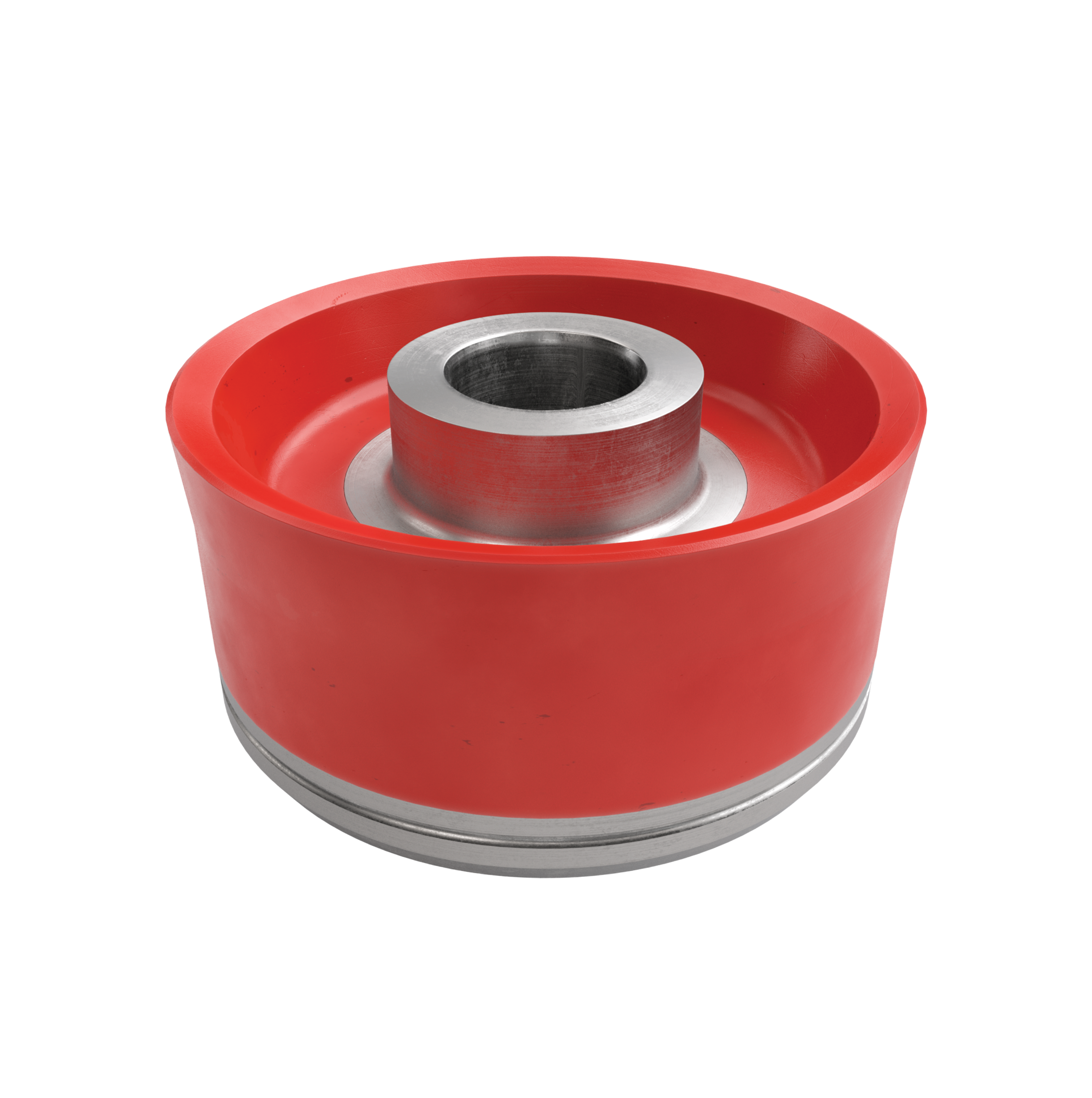
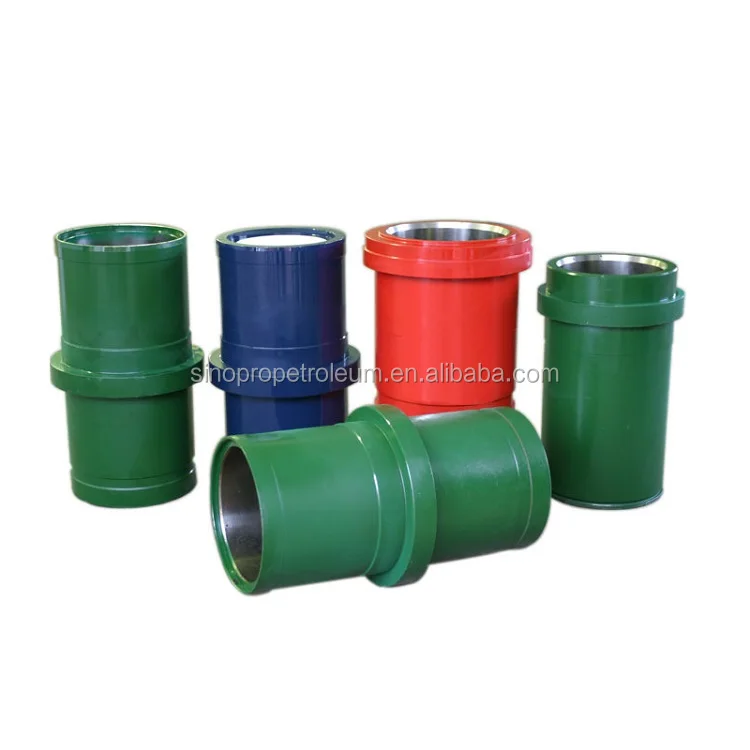
Lake Petro provides high quality Mud Pump Parts including Mud Pump Liners, Mud Pump Fluid End Module, piston, Valve and Seat etc. With more than 10 years of experience in the oil and gas industry, we are dedicated to help and support our loyal clients with the most cost-effective and quality Liners and Pistons. We also provide mud pump price and mud pump for sale.
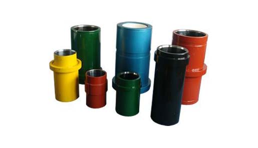
We offer Liners with Ceramic (Zirconia and Aluminium oxide) and Steel (Metal and Bi-metal) materials for all common brands of the mud pump and triplex mud pump.
Bi-metal liners (double metal liners) are made of forged steel shell and wear-resistant sleeve of high chromium iron. In the production process, the size accuracy should be strictly controlled, which can ensure that they can be easily and stably installed. The inner sleeve with high finish and hardness is wear-resistant, corrosion-resistant and has a long service life. The bi-metal liners are suitable for a lot of bad working conditions. Its service life is more than 800 hours.
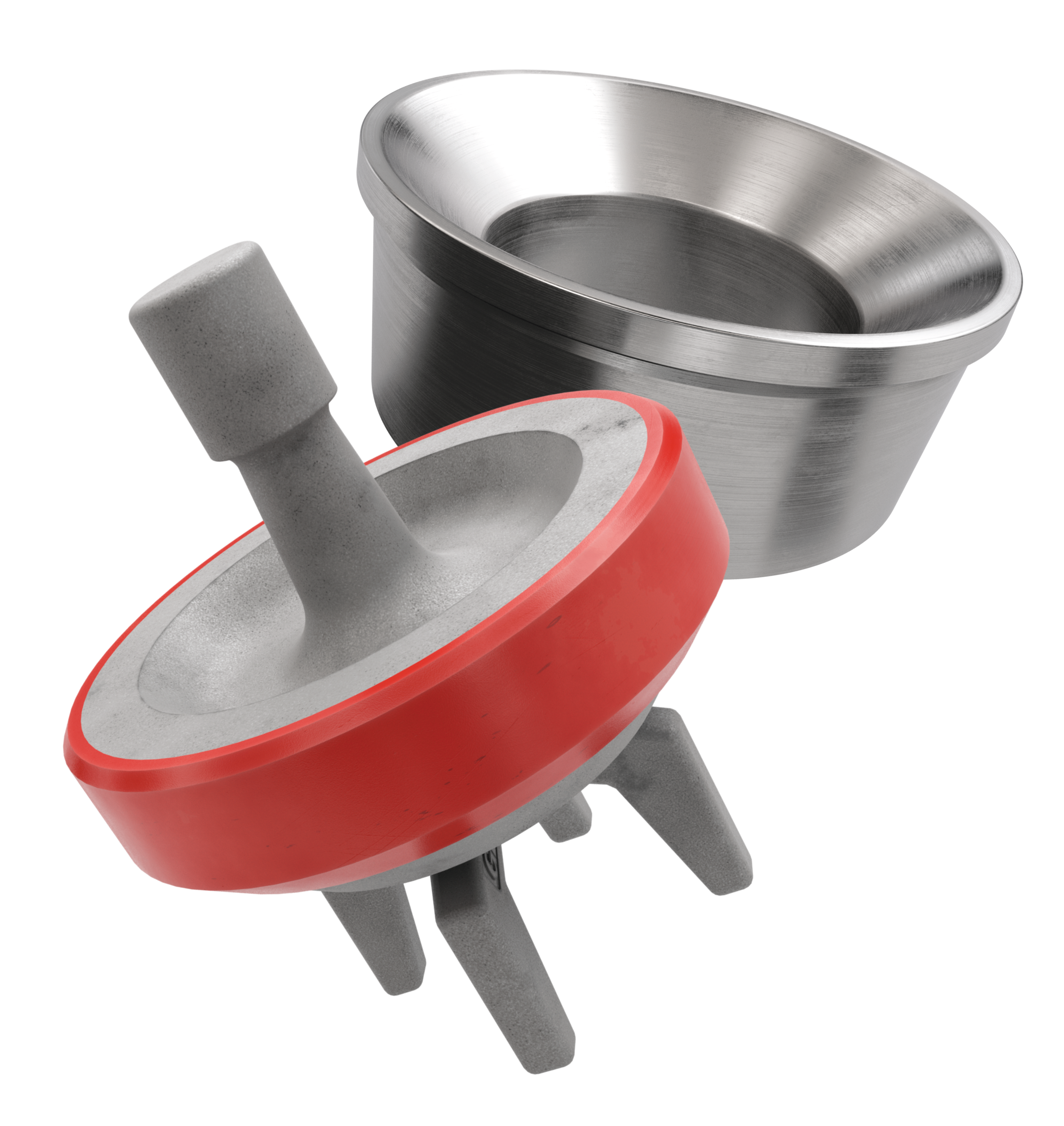
Ceramic Liners are made of a ceramic inner sleeve and a forged steel outer shell. The service life of ceramic liners is about 4000 to 10000 hours, the minimum time is at least 2000 hours, which is a lot more than bi-metal liners. Because of the phase transformation toughen technology, the ceramic liners have the features of wear-resistance, erosion-resistance, high-pressure-resistance, high hardness and strength. Zirconia type and Alumina type are common type of ceramic sleeve. Compared with Alumina type, Zirconia type liners have better toughness properties and a much longer service life. Piston wear and water consumption for lubrication can be reduced as well.
Seal Rings for Liner packing are also important. Liner Seal Rings is designed and made with hard corner which is an integral part of seal rings and soft nitrile element rubber center. We could provide reliable liner Seal Rings for our customers could order them at the same time.
All Lake Petro liner products are interchangeable with O.E.M. products. Meanwhile, we provide customized Liners according to drawings. Our liners, also with our other mud pump spares, are supplied for use in Honghua, F-Series, Bomco, Emsco and National lines of triplex drilling pumps. Let Lake Petro be your one-stop shop for your whole fleet of pumps. Please refer to “Suitable Pump Models” Lable for more details.
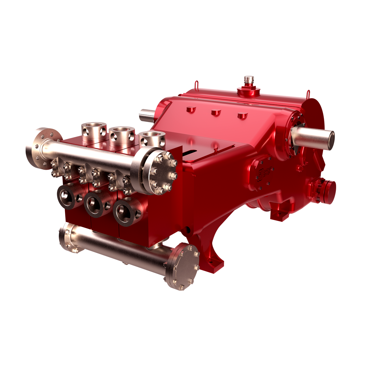
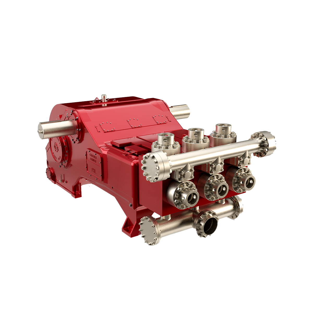
GDEP is the original creator of the drilling pump and continues to set the standard for durable, high-quality drilling pumps that can withstand the world’s toughest drilling environments. Starting with our PZ7 and rounding out with the market"s most popular pump, the PZ1600, our PZ Series of pumps are the perfect choice for today"s high-pressure drilling applications.

Rig pump output, normally in volume per stroke, of mud pumps on the rig is one of important figures that we really need to know because we will use pump out put figures to calculate many parameters such as bottom up strokes, wash out depth, tracking drilling fluid, etc. In this post, you will learn how to calculate pump out put for triplex pump and duplex pump in bothOilfield and Metric Unit.
Pump Parts - Ajax T-150, Pumps & Parts, Used crankshaft for Ajax T-150, crankshaft journal diameter 4.5", crankshaft extension diameter 4" , More Info
Pump Parts - Mud Pump Parts & Complete Units: Liners, Pistons, Rubbers, Rods, Valves, Seats, Springs, Inserts (Bean, BJ, CAT, EMSCO, Ellis Williams, FMC, Failing, GASO, Gardner Denver... More Info
Pump Parts - Mud Pump Parts & Complete Units: Liners, Pistons, Rubbers, Rods, Valves, Seats, Springs, Inserts (Bean, BJ, CAT, EMSCO, Ellis Williams, FMC, Failing, GASO, Gardner Denver... More Info
Pump Parts - BUTTERWORTH T-375M Triplex Water Blaster Pump, Pumps & Parts, Used Butterworth T-375M Triplex Water Blaster Pump, 1.4375" plungers x 3.75" stroke, max 10,000 PSI, missing... More Info
Pump Parts - Mud Pump Parts & Complete Units: Liners, Pistons, Rubbers, Rods, Valves, Seats, Springs, Inserts (Bean, BJ, CAT, EMSCO, Ellis Williams, FMC, Failing, GASO, Gardner Denver... More Info
Pump Parts - Chinese 3DS-18.5/21.5, Pumps & Parts, Brand new triplex pump, 1.921" plungers, 4.117" crank extension, 5.285" stroke, 4"#150FF suction flange, 2" 5000 PSI API discharge f... More Info
Pump Parts - DOWELL PG03 4.5x5 Triplex Cementing Pump, Pumps & Parts, Used Dowell PG-03 Triplex Cementing Pump, 4 1/2" Metal Plungers x 5" Stroke, c/w Factory Chain Case, Magnesium Po... More Info
Pump Parts - DOWELL PG03 4.5x5 Triplex Cementing Pump, Pumps & Parts, Used Dowell PG-03 Triplex Cementing Pump, 4.5" metal plungers x 5" stroke, steel block fluid end for cementing or... More Info
Pump Parts - DOWELL PG05 4.5x5 Triplex Cementing Pump, Pumps & Parts, Used Dowell PG-05 Triplex Cementing Pump, 4 1/2" Metal Plungers x 5" Stroke, Steel Fluid End c/w Factory Chain Ca... More Info
Pump Parts - Mud Pump Parts & Complete Units: Liners, Pistons, Rubbers, Rods, Valves, Seats, Springs, Inserts (Bean, BJ, CAT, EMSCO, Ellis Williams, FMC, Failing, GASO, Gardner Denver... More Info
Pump Parts - Mud Pump Parts & Complete Units: Liners, Pistons, Rubbers, Rods, Valves, Seats, Springs, Inserts (Bean, BJ, CAT, EMSCO, Ellis Williams, FMC, Failing, GASO, Gardner Denver... More Info
Pump Parts - EMSCO D-300, 4.75-7.25 x 14 Duplex Mud Pump Package, Pumps & Parts, Used Emsco D-300 Duplex Mud Pump Package, 5.5" liners x 14" Stroke, c/w Detroit Series 60 Diesel Engin... More Info
Pump Parts - EMSCO F650 Triplex Mud Pump, Pumps & Parts, Used Continental Emsco F650 Triplex Mud Pump, 5 1/2" Pistons x 8" Stroke c/w Mud Gauge, Relief Valve, Pulsation Dampener, Quic... More Info
Pump Parts - Mud Pump Parts & Complete Units: Liners, Pistons, Rubbers, Rods, Valves, Seats, Springs, Inserts (Bean, BJ, CAT, EMSCO, Ellis Williams, FMC, Failing, GASO, Gardner Denver... More Info
Pump Parts - Mud Pump Parts & Complete Units: Liners, Pistons, Rubbers, Rods, Valves, Seats, Springs, Inserts (Bean, BJ, CAT, EMSCO, Ellis Williams, FMC, Failing, GASO, Gardner Denver... More Info
Pump Parts - Mud Pump Parts & Complete Units: Liners, Pistons, Rubbers, Rods, Valves, Seats, Springs, Inserts (Bean, BJ, CAT, EMSCO, Ellis Williams, FMC, Failing, GASO, Gardner Denver... More Info
Pump Parts - Gardner Denver GD45T Triplex Injection Pump, Pumps & Parts, Used frame for Gardner Denver GD45T (PS-25) triplex pump, bare case , More Info
Pump Parts - Gardner Denver PA-8 Triplex Mud Pump, Pumps & Parts, Used Gardner Denver PA-8 Triplex Mud Pump (predecessor to the Gardner Denver PAH), 4.5" metal plungers x 8" stroke, c... More Info
Pump Parts - Gardner Denver PAH 4 1/2 x 8 Triplex Mud Pump, Pumps & Parts, Used Gardner Denver PAH 4 1/2 x 8 Triplex Mud Pump Package, 4.5" Metal plungers x 8" stroke, Detroit 8V-71 d... More Info
Pump Parts - Gardner Denver PE-5 3x5 Triplex Mud Pump, Pumps & Parts, Used power end for Gardner Denver (SMC) PE-5 (T-165-5) triplex pump, 5" stroke, no fluid end , More Info
Some of our largest competitors use a cheaper alumina-ceramic sleeve to make their liners. Although these liners last a little longer than standard chrome-iron liners, they only last about half as long as zirconia-ceramic liners. Our liners are made from zirconia-ceramic material in order to provide the longest life and best wear performance.

Our 500 horsepower TT-660 pump package offers up to 720 GPM normal pumping volumes. This is one of our best selling pumps for HDD applications, because it offers high volumes at relatively low pressures. It can produce pressures required to run a mud motor and the volume to clean the hole, while running the largest of hole openers. It features a smaller footprint and lighter weight than competing models, making it completely legal load size and weight in most instances. The standard TT-660 skidded package weighs in at a mere 26,000 lbs. Available as a bare pump, with chain box, or a complete skidded package.
Our 600 horsepower TT-680 pump package offers up to 625 GPM normal pumping volume. Capable of acheiving flow rates greater than pumps three times its size and weight, the standard TT-680 skidded package weighs in at a mere 28,000 lbs. Available as a bare pump, with chain box, or a complete skidded package.
Used Ideco T-1300 Triplex Mud Pump, rated to 1300 HP @ 120 strokes per minute, 5" - 7.5" pistons x 12" Stroke, pump is complete. 7.5" liners = 2428 PSI, 7" liners = 2787 PSI, 6.5" liners = 3232 PSI, 6" liners = 3797 PSI, 5.5" liners = 4514 PSI, 5" liners = 5462 PSI
We stock fluid end parts for the5×6 mud pump, 5×6-1/4 FM45 mud pump, 5×8 mud pump, 5-1/2×8 mud pump, 5X10 mud pump, 4-1/2×5 mud pump, 7-1/2×8 mud pump, and 7-1/2X10 mud pump. The Gardner Denver mud pump model numbers for the above pumps are as follows: 5X6-FGFXG, 5X8-FDFXX, 5-1/2X8-FDFXX, 5X10-FDFXD, 4-1/2X5-FFFXF, 7-1/2X8-FYFXX, 7-1/2X10-FYFXD. We also handle Wheatley, Gaso, Worthington, Failing and Centerline parts and pumps. We also stock Foot Valve, Liner Puller, Valve Seat Puller, (4″ Inline Check Valve. Our Gardner Denver mud pump parts are not only competitively priced, they are also made in the USA. Oil Recommended by Gardner Denver. Call any of our experienced representatives to get the help and knowledge you deserve.

Technical Specification Pre-Shipment And Storage PS-4030 02 Preservation For New-Build NOV Triplex Mud Pumps
Product Information Bulletin Triplex Mud Pumps Power 01-05-01-MP 06 End Lubrication Oil Additive and wear-in Period
RIG/PLANT REFERENCE REFERENCE DESCRIPTION Triplex Mud PumpADDITIONAL CODE SDRL CODE TOTAL PGS This document contains proprietary and confidential information National Oilwell Varco which belongs to National-Oilwell Varco, L.P., its affiliates orREMARKS subsidiaries (all collectively referred to hereinafter as "NOV"). It is loaned for limited purposes only and remains the property of NOV. 11000 Corporate Centre Drive Reproduction, in whole or in part, or use of this design or Suite 200MAIN TAG NUMBER DISCIPLINE distribution of this information to others is not permitted without the Houston, Texas 77041 express written consent of NOV. This document is to be returned to NOV upon request and in any event upon completion of the use for U.S.A.CLIENT PO NUMBER which it was loaned. This document and the information contained and represented herein is the copyrighted property of NOV. Phone: +1-281-854-0400 National Oilwell Varco Fax: +1-281-854-0607CLIENT DOCUMENT NUMBER DOCUMENT NUMBER REV
This specification covers the preservation and storage procedure for shipment of new-build NOV Triplex Mud Pumps shipped from the manufacturing plant.
This specification is intended to provide preservation of new-build NOV Triplex Mud Pumps for six (6) months from the shipment of the mud pump from the manufacturing facility. If a pump is to be stored for a period of time exceeding six (6) months, additional precautions should be taken as outlined in this specification.
National Oilwell Varco recommends that all pumps are inspected for any signs of corrosion and for proper preservation at a minimum every three (3) months for pumps stored outside and every six (6) months for pumps stored indoors.
Drain all water and clean out liner wash tank. Remove drain plug in bottom of liner wash pump and drain water then reinstall plug. Remove discharge flange from liner wash pump and pour one (1) pint of inhibiting oil-based concentrate (Cortec VpCI 329 Vapor Corrosion Inhibiting oil-based concentrate or equivalent) into liner wash pump. Rotate two (2) revolutions by hand to distribute the product. Re-install discharge flange.
Drain all oil from pump power end sump and remove crosshead covers and inspection covers. Clean out oil sump as per National Oilwell PS-3081 (Mud Pump Cleanliness). Spray all internal machined parts of power end and crosshead area with inhibiting oil-based concentrate (Cortec VpCI 329 Vapor Corrosion Inhibiting oil-based concentrate or equivalent). Rotate pump turn and re-spray. Pour quantity of inhibiting oil-based concentrate specified in the table below into power end sump.
Mud Pump Models Quantity of Inhibitor 14P, FC 2200 5 Gallons 12P, 10P, HD or A1700/1400PT, FB/FC/FD 1600, FB 1300 3 Gallons 9P, 8P, B or A850-1100PT, F/FD 1000, F 800 2 Gallons 7P, A600PT, FD 500 1 Gallon
For pumps equipped with chain drives, spray internal machined parts inside chain cases with inhibiting oil-based concentrate (Cortec VpCI 329 Vapor Corrosion Inhibiting oil based concentrate or equivalent).
Remove fluid end valve covers, seals, valves springs and seats and treat internal cavities of fluid ends, discharge manifold, discharge strainer block and suction manifold with rust preventative (CRC SP400 or equivalent). Coat threads with anti-seize (KOPR KOTE 10002 or equivalent) and coat bottom side of valve cover with rust preventative. Reinstall seals and fluid end valves covers hand tight. Customer liners, pistons, piston rods, valves, seats, springs and liner retention parts are not used for plant testing. These expendables are checked for preservation when packed and then shipped with the loose parts.
Remove breather and pack with loose parts for later shipment with pump. Seal breather hole with a greased solid plug. Affix a warning label near the breather opening (see Exhibit 1).
Cover large diameter pipe and other openings with hardboard and protective plastic wrap. Liner bushing openings shall also be covered and sealed.
Spray all machined unpainted loose parts and expendables to be shipped with pump with rust preventative (CRC SP400 or equivalent). All parts will be wrapped or boxed to prevent damage.
Affix one (1) warning label (see Exhibit 2) to the power end pump cover and one (1) warning label on the fluid end assembly of the pump. Affix warning labels on each loose part container. In cases where the equipment will be boxed at an offsite export packer, a sufficient number of warning labels will be supplied with the shipment.
Indoor storage is preferred whenever possible; but if outside storage is required, ensure pump is stored away from salt water spray, sand blast or other adverse conditions. It is highly recommended that ship loose parts be stored indoors to eliminate conditions that promote condensation and direct sources of moisture.
Note: It is recommended that inspections be carried out on six (6) month cycles when pumps are in indoors and three (3) month cycles when stored outside.
Any pump that has been in storage will need a thorough inspection prior to start-up to insure it has not been damaged in any way and that all parts are properly in place. Failure to observe the following points can result in serious damage. Before servicing the pump, the power end sump and chain drives housings will need to be drained of any inhibiting additive. The Cortec brand products used for preservation are compatible with all lubricating oils and need not be totally removed when putting equipment into service.
To service the Fluid End after storage and prior to start-up, remove covers and thoroughly clean and inspect inside of the fluid end cylinders. Properly install valves, pistons, liners and all other fluid end parts. Carefully tighten all bolts, nuts, studs and working connections to specified torque requirements.
TRIPLEX MUD PUMP GDH 02PREPARED BY DATE CHECKED BY DATE
DOCUMENT TITLE: Commissioning Procedure, FB/FD-1600 Triplex Mud Pump DOCUMENT OR DRAWING NO. PAGE 2 of ENGINEERING EDN-1688 12SUBJECT COMMISSIONING PROCEDURE, FB/FD-1600 APPROVED REVISED DATE REV.
TRIPLEX MUD PUMP GDH 02PREPARED BY DATE CHECKED BY DATE
1. Power End.................................................................................................. 3 2. Main Electric Drive Motors 3 3. Auxiliary A/C Motors. 4 4. Instrumentation........................................................................................... 4 5. Liner Wash System..................................................................................... 4 6. Fluid End.................................................................................................... 4 7. Suction Dampener/Desurger....................................................................... 4 8. Pulsation Dampener.................................................................................... 4 9. Pressure Gauge............................................................................................ 5 10. Reset Relief Valve....................................................................................... 5 11. Discharge Strainer 5 12. Mud Pump Drive Assembly. 5 a. Belt Drive Units 5 b. Chain Drive Units. 5
TRIPLEX MUD PUMP GDH 02PREPARED BY DATE CHECKED BY DATE
The initial startup procedures are written to assist the operator in preparing the pump packages for normaloperation. The startup procedures are separated into two categories: Part I: Pre-Commissioning, and PartII: Commissioning Procedures. It is suggested that a copy of these pages be made for each pump to beused as a check-off sheet.
Note: The rust preventative on the internal surfaces of the pump is oil-soluble and is compatible with the lubricants recommended above. It is not necessary to flush and drain unless the preservative has become contaminated (water, sand etc.).
TRIPLEX MUD PUMP GDH 02PREPARED BY DATE CHECKED BY DATE
Clean liner wash tank, if needed, and fill with fresh clean water. Ensure that supply hoses and spray nipples are installed correctly. Start pump and adjust regulating valve to maximum flow without splash onto the extension rods.
Check to assure that all liners, valves, and pistons are installed properly in accordance with the installation instructions. Ensure that the liner end covers are installed on the rear end of the liners. Ensure that the baffle discs are installed on the end of the crosshead extension rods. Clean grease and paint from the exposed parts of the extension rods, checking for burrs. Coat rods with a light oil.
NOTE: When charging the bladder, make sure that the mud pump suction line valve has been closed and that all pressure has been bled off of the suction manifold surrounding the suction desurger
If a dampener is used, charge dampener with a hand-operated air pump to 10 PSI (0.7 bar). Once pump operations have been started, check the operation of the suction dampener by inspecting the sight glass. Add or release air pressure through the Shraeder valve to keep the diaphragm between the midpoint and the bottom of the sight glass.
TRIPLEX MUD PUMP GDH 02PREPARED BY DATE CHECKED BY DATE
Check the installation and the setting. NO SHUT-OFF VALVE is to be between the pump discharge and the relief valve. Ensure that piping from the discharge port goes directly to the mud tank/pit and is securely tied down, with a minimum downward slope of 1/4 per foot. Ensure that piping has pressure rating equal to the relief valve highest setting.
Check the chain guards to ensure that the chains will not drag on the guard. Check the oil pump to ensure that the relief valve is installed on the suction side. Start the pump and ensure that the spray nozzles are spraying oil over the full width of the chain. Adjust the relief valve to 15-25 PSI output with the warm oil. DOCUMENT OR DRAWING NO. PAGE 6 of ENGINEERING EDN-1688 12SUBJECT COMMISSIONING PROCEDURE, FB/FD-1600 APPROVED REVISED DATE REV.
TRIPLEX MUD PUMP GDH 02PREPARED BY DATE CHECKED BY DATE
Operation of the pump in parallel to check the SCR-Motor assignments and controls, volumetric displacement and mudline systems are at the option of the purchaser.
Check the discharge mudline to assure that all necessary valves are open. Ensure that the mud tanks are full of test fluid (mud/water) prior to startup.
Make the desired assignment of the SCR-Motor Control System to the pump motors, and open the throttle slightly. Check to ensure that charge pump and liner wash motors have started.
If no immediate problems are encountered, slowly throttle the pump to approximately 60 SPM and continue operating the mud pump while making the following inspections to assure that all systems are working properly:
Adjust the regulator valve for proper volume of cooling fluid. 10 US Gallons (38 Liter) per minute per liner. Check the coolant temperature. 150F (66C) maximum.
TRIPLEX MUD PUMP GDH 02PREPARED BY DATE CHECKED BY DATE
Pump A/C motor operating properly. Valves open for the proper volume of drilling fluid. Gauges/controls functioning properly.
Check the valve for proper relief setting. The valve should be set 10% above the pressure rating for the liner size being used. Refer to the nameplates on each side of the pump or the pump datasheet to obtain the operating pressure for that particular size liner. DOCUMENT OR DRAWING NO. PAGE 8 of ENGINEERING EDN-1688 12SUBJECT COMMISSIONING PROCEDURE, FB/FD-1600 APPROVED REVISED DATE REV.
TRIPLEX MUD PUMP GDH 02PREPARED BY DATE CHECKED BY DATE
The following are basic guidelines for conducting of an eight (8) hour operational test. The pump was test run under pressure in the manufacturing plant but with different motors and drives.
RATED LINER PRESSURE*...180 min. @ 100 SPM _______ _______ * Not to exceed pressure rating of fluid end. DOCUMENT OR DRAWING NO. PAGE 9 of ENGINEERING EDN-1688 12SUBJECT COMMISSIONING PROCEDURE, FB/FD-1600 APPROVED REVISED DATE REV.
TRIPLEX MUD PUMP GDH 02PREPARED BY DATE CHECKED BY DATE
The overall performance of the unitized pump package should be continuously monitored during the eight hour test program. The following checks should be made and recorded each two hours of operation.
TRIPLEX MUD PUMP GDH 02PREPARED BY DATE CHECKED BY DATE
TRIPLEX MUD PUMP GDH 02PREPARED BY DATE CHECKED BY DATE
TRIPLEX MUD PUMP GDH 02PREPARED BY DATE CHECKED BY DATE
Triplex Mud Pump For Models: FD-500, FD-800, FD-1000 & FD-1600
RIG/PLANT REFERENCE REFERENCE DESCRIPTION Triplex Mud PumpADDITIONAL CODE SDRL CODE TOTAL PGS This document contains proprietary and confidential information National Oilwell VarcoREMARKS which belongs to National Oilwell Varco; it is loaned for limited 1530 W Sam Houston Pkwy. N purposes only and remains the property of National Oilwell Varco. Reproduction, in whole or in part; or use of this design or Houston, TX 77043MAIN TAG NUMBER DISCIPLINE distribution of this information to others is not permitted without the Phone 713-935-8000 express written consent of National Oilwell Varco. This document is Fax 713-935-8382 to be returned to National Oilwell Varco upon request and in anyCLIENT PO NUMBER event upon completion of the use for which it was loaned. National Oilwell VarcoCLIENT DOCUMENT NUMBER DOCUMENT NUMBER REV
IN ORDER TO PREVENT PERSONAL INJURY during performance of any maintenanceor inspection procedures, this equipment must be shut down and not operating. Eachmotor and generator is equipped with a motor cutout switch. This switch should be IN,and the safety bar in place, when any maintenance or inspection procedures areperformed. Employ good mechanical practices when making maintenance repairs,adjustments, inspections, etc.
When operating all mechanical and electrical equipment, all safety devices must beengaged, properly adjusted, and in good operating condition, including overtravel devicesfor traveling blocks, warning or shutdown devices for engines, etc.
PREFACE.................................................................................................................................... 31 INSTALLATION OF NEW PUMP ................................................................................... 112 SETTING THE PUMP ..................................................................................................... 11 2.1 Land Installations.................................................................................................. 113 SUCTION SYSTEM REQUIREMENTS........................................................................... 16 3.1 Caution ................................................................................................................. 164 PREPARATION OF POWER END ................................................................................. 17 4.1 Power End Lubrication.......................................................................................... 17 4.2 Installation of Crosshead Extension Rods and Diaphragm Stuffing Box Seals..... 185 PISTON AND LINER COOLING SYSTEM ..................................................................... 19 5.1 Stationary spray (View A, Fig. 6) .......................................................................... 20 5.2 Moving Nozzle ...................................................................................................... 206 ASSEMBLY OF FLUID END PARTS ............................................................................. 23 6.1 Valves and Seats.................................................................................................. 237 FD-500, FD-800 & FD-1000............................................................................................ 24 7.1 Liners.................................................................................................................... 25 7.2 Piston Rod ............................................................................................................ 25 7.3 Piston Rod Clamps ............................................................................................... 25 7.4 Liner Cage and Lower Valve Guide ...................................................................... 26 7.5 Cylinder head ....................................................................................................... 26 7.6 Discharge Valve Pot Covers ................................................................................. 268 FD-1600 .......................................................................................................................... 27 8.1 Liner...................................................................................................................... 28 8.2 Piston Rod ............................................................................................................ 28 8.3 Piston Rod Clamps ............................................................................................... 29 8.4 Lower Valve Guide and Cylinder Head................................................................. 29 8.5 Discharge Valve Pot Covers ................................................................................. 29 8.6 Discharge Manifold all models .............................................................................. 30
8.7 Suction Flange...................................................................................................... 30 8.8 Accessory Manifold............................................................................................... 309 LUBRICATION ............................................................................................................... 31 9.1 Minimum Operating Speeds ................................................................................. 32 9.2 Controlled Flow Splash System ............................................................................ 33 9.3 Total Pressure lubrication System ........................................................................ 3410 MAINTENANCE OF THE LUBRICATION SYSTEM ...................................................... 3611 MAINTENANCE.............................................................................................................. 38 11.1 Power End ............................................................................................................ 38 11.2 Roller Bearings ..................................................................................................... 39 11.3 Pinion Shaft Assembly.......................................................................................... 41 11.4 Crankshaft Assembly (Fig. 16) ............................................................................ 42 11.5 Installing Crankshaft Assembly in Frame.............................................................. 46 11.6 Installation of Crosshead Guides .......................................................................... 48 11.7 Installation of Crossheads .................................................................................... 49 11.8 Checking crosshead alignment............................................................................. 5112 FLUID END MAINTENANCE.......................................................................................... 51 12.1 Fluid Cylinder Blocks ............................................................................................ 52 12.2 Suction Manifold ................................................................................................... 53 12.3 Discharge Manifold ............................................................................................... 53 12.4 Cylinder Head Thread Ring .................................................................................. 54 12.5 Welding and Repairs ............................................................................................ 54 12.6 Welding Procedures ............................................................................................ 58 12.7 Repairs to Valve Pot Cover Bore .......................................................................... 59
FD-500 (mm) FD-800 ( mm ) FD-1000 ( mm ) FD-1600 ( mm ) A 3-11-3/8 (1203) 4-8-7/8 (1445) 4-10-5/8 (1489) 5-0-5/8 (1540) B --- --- --- -- ---- -- 5-7-13/16 (1722) C 3-2-15/16 (989) 3-4-1/2 (1029) 3-8-3/8 (1127) 4-0-1/8 (1222) D 3-11-3/16 (1198) --- -- ---- -- 4-8-1/16 (1424) E 12-1/16 (305) 12-7/16 ( 316 ) 13-3/4 ( 349 ) 13-3/16 ( 335 ) F 3-1 (939) --- -- ---- -- 4-3-3/4 (1315) G 3-8-1/2 (1197) 3-11-1/8 (1197) 4-5-1/2 (1359) 4-11-3/4 (1518) H 4-9 (1448) 5-1-3/4 (1568) 8-0 92438) 7-10 (2388) J 6-9-7/8 (2079) 7-11-3/8 (2423) 8-4-1/4 (2546) 8-11-7/8 (2740)** K --- --- 4-6-1/4 (1378) 4-6-7/8 (1394) 4-10-1/4 (1480) L (Dia.) 5.5 (139) 7.00 (177.8) 7.750 (196.85) 8.500 (215.90) (Keyway) 1-1/4 x 5/8 (31.7 x 15.8) 1-3/4 x 7/8 (44.45 x 22.225) 2 x 1 (50.8 x 25.4) 2 x 1 (50.8 x 25.4) M 3-11 (1193) 4-3-3/8 (1305) 4-9-3/8 (1457) 5-5-3/4 (1670) N 5-0-3/4 (1543) 5-5-1/4 (1657) 5-11-1/8 (1807) 6-10 (2083) P 4-3-3/8 (1305) 4-6 (1372) 5-1 (1549) 6-1-3/8 (1864) Q 12-0 (3658) 13-0 (3962) 13-6 (4115) 16 (4877) R 1-3-5/16 (389) 1-3-5/8 ( 397 ) 1-6-7/8 ( 479 ) 1-9-3/4 ( 553 ) S 10 (254) 10 ( 254 ) 12 ( 305 ) 12-1/4 ( 311 ) T --- --- 1-1 ( 330 ) 1-1 ( 330 ) 1-4-1/2 ( 419 ) U --- --- 2-0-1/2 ( 622 ) 1-2-3/8 ( 365 ) 1-1-3/4 ( 349 ) V 3-0-3/4 (933) 3-1-1/2 ( 953 ) 2-2-3/8 ( 670 ) 2-6-1/4 ( 768 ) W 9-3/4 (250) 10-3/4 ( 273 ) 10-3/4 ( 273 ) 12-9/16 ( 319 ) X 1-4-7/8 (422) --- -- ---- -- 1-7-1/4 ( 489 )
FD-500 FD-800 FD-1000 FD-1600 Max. Liner Size 6-3/4 (171.45 mm) 6-3/4 (171.45 mm) 6-3/4 (171.45 mm) 7-1/2 (190.5 mm) and stroke 7-1/2 (191 mm) 9 (228.6 mm) 10 (254 mm) 12 (304.8 mm) Nominal HP 500 HP 800 HP 1000 HP 1600 HP Rating @ 165 SPM @ 150 SPM @ 140 SPM @ 120 SPM Type Gear Herringbone Herringbone Herringbone Double Helical 4.31:1 4.31:1 4.31:1 4.31:1 Lubrication Pressure and Splash to all Moving Parts Valve Pots API No. 6 API No. 6 API No. 6 API No. 7 Approx. Wt. 18,657 (8,463 kg) 26,603 (12,067 kg) 33,770 (15,318 kg) 46,820 (21,238 kg) (Lbs.)
Your National Oilwell Varco pump has been completely assembled and test operated under pressure before being shipped to the field. Unless otherwise instructed, the lubrication is drained from the power end and the expendable parts are removed from the fluid end. Before putting the pump into service, the following precautions and operations must be performed or checked.
2 SETTING THE PUMP The skids under the National Oilwell Varco pumps are suitable for most any type of installation. It should be noted, however, that the box type construction of the power frame has high resistance to bending but relatively less resistance against twist. Therefore, the support under the pump must be level and adequate to support the weight and operating forces exerted by the pump.
2.1 Land Installations In land installations, a mat of 3 X 12 (76.20 mm x 304.8 mm) boards laid side crosswise to the pump skids for the entire length, or at a minimum, at the points indicated in Fig. 2, is usually sufficient. The boards should be a few feet wider than the width of the pump skid runners. Wet or marshy locations may require a more stable foundation.
Suitable means, such as National Oilwell Varco pump spacers as shown in Fig. 3, should be used to keep the pump anchored and the drive in alignment. National Oilwell Varco mud pump spacers provide 8-1/2 (215.9mm) adjustment. Any desired length may be obtained by lengthening the standard pipe spacer, which is made of 3 (76.20mm) extra strong pipe.
2.1.1 Permanent Installations On permanent installations such as barge, platform, structural base, or concrete slab, where pump skids are bolted down, it is essential that the skids be properly shimmed to prevent possibility of twisting or distorting the power frame. The pump skids must sit solid on all shim points with bolts loose.
On barge installations, the pump skids are generally bolted down to T-beams running parallel and in line with the pump skids. Install shims at points shown in Figs. 2 and 4 and observe caution of proper shimming to prevent twist or distortion.
On installations where the power unit or electric motor is mounted integrally with the pump skids, the preferred installation would be to set the pump package on the T-beam skids and provide retention blocks rather than bolts to hold it in place. This will allow the pump to float and minimize the transfer of barge deck or platform distortion into the frame.
2.1.2 Installation of the Drive The drive between the mud pumps and the power source, whether V-belts or multi-width chains, should be installed with the greatest care to assure maximum operating life with minimum of unexpected or undesirable shutdowns due to drive failures.
The final alignment of the V-belt sheaves should be checked after the V-belts have been installed and adjusted to their operating tension. If the sides of the sheaves are of equal distance from the centerline of the groove, check alignment by stretching TWO strings (fish line or piano wire preferred) along one side of the two sheaves, one above and one below the centerline, and moving one of the sheaves until the strings touch four points on the side of the sheave rims. This will determine that the centerline of the drives are parallel and the faces of the sheaves are square.
Adjust the belt tension by moving the sheaves apart until all of the sag has just been eliminated from the tight side of the belt and some of the belts on the slack side. Then increase the centers approximately (13mm) for each 100 (2540 mm) center distance. Example: On 150 (3810 mm) center, move pump an additional (19.5 mm).
DO NOT OBTAIN BELT TENSION BY PICKING UP END OF PUMP AND ALLOWING BELTS TO TIGHTEN UNDER WEIGHT OF PUMP AS END IS BEING LOWERED TO THE GROUND.
The pump drive chain lubrication system on the majority of National Oilwell Varco pumps is an independent system having its own oil pump, reservoir, and drive. Fill chain case to the indicated level with a non-detergent oil as follows:
- Daily check of oil level. - Daily check on condition of oil. - Frequent check on oil pressure. (5-15 psi) (.352 - 1.06 kg/cm) - Volume of oil being applied to chain. - Condition of nozzles in spray tube. - Condition of oil pump drive (V-belts or chain)
NOTE: Oil pressure may be adjusted with the pressure relief adjusting screw on the rear of the pump housing. Pressure drops may also indicate suction and discharge filter screens need cleaning.
3 SUCTION SYSTEM REQUIREMENTS Individual installation conditions will dictate the design of the suction system. The suction of the FD-series pumps must have a positive head (pressure) for satisfactory performance. The optimum suction manifold pressure is 20-30 psi (1.75-2 kg/cm) for maximum volumetric efficiency and expendable parts life. This head pressure is best supplied by a 5 x 6 centrifugal pump with 40 h.p. 1150 rpm electric motor. This type of drive requires a device to automatically start and stop the centrifugal pump motor simultaneously with the triplex pump. On DC electric powered rigs a signal can usually be supplied from the DC control panel to energize a magnetic starter when the mud pump clutch air line will provide a set of contacts for energizing the magnetic starter when clutch is engaged.
The charging pump can also be belt driven from the triplex pinion shaft charging type of drive is not as efficient at slow speeds with viscous fluids.
Under some conditions the FD-Series pumps may be operated without a charging pump, provided the fluid level in mud pits is higher than the top of the liners, fluid being pumped is low viscosity and suction line must be short, straight and of at least the same diameter as suction manifold inlet.
The suction lines should be piped with valve arrangements so the charging pump can be by-passed so operation can be continued in event of charging pump failure or for maintenance. Operation without a charging pump can be improved by replacing the suction valve springs with a weaker spring.
Suction desurgers are a very effective aid for complete filling of the liners and dampening pulsations in the suction line which results in a smoother flow in the discharge line. If your pump is equipped with a suction desurger it must be pre-charged with compressed air before operations are begun. See suction desurger manual for charging instructions.
3.1 Caution Do not pipe the return line from the shear relief valve back into the suction system as a relief valve operation will cause a sudden pressure rise in the system vastly greater than the system pressure ratings, resulting in damage to manifold, suction desurger and centrifugal pump.
4 PREPARATION OF POWER END Your National Oilwell Varco pump has been completely assembled and test operated before being shipped to the field. Unless otherwise instructed, the lubrication is drained from the power end, and the expendables are removed from the fluid end for storage protection. Before operating the pump, the following must be performed or checked:
Before installing lubricant, open inspection door in cover and check oil reservoir for possible accumulation of condensation, etc., and drain and flush by removing the pipe plugs on each side of the pump.
Add the proper type and quantity of lubrication in the power end. Refer to the Lubrication Section of this manual, or lubrication plate on pump frame for type and quantity required.
Recheck oil level after pump has operated for a period of 15 minutes. Shut pump down and allow approximately five minutes for the oil level to equalize. Check at oil level gauge, Item 1, Fig. 1. It is usually necessary for a few more gallons of oil to be added due to a certain amount being retained in the crosshead area and frame cavities.
With reference to Figure 5, remove the diaphragm stuffing box and plate (1) and rotate pump so that crosshead is at the front of the stroke. Thoroughly clean the front of the crosshead and the face of the crosshead extension rod. Insert alignment boss on crosshead extension rod into the crosshead bore and tighten the retainer bolts (2) to the following torque. Safety wire bolt heads.
5 PISTON AND LINER COOLING SYSTEM Proper attention must be paid at all times to assure adequate cooling fluid is being applied to the piston and liner assembly. Stoppage of the cooling fluid will result in almost instant failure of the piston rubbers and possibly extensive damage to the liner bore.
Two types of piston and liner cooling systems have been used on National Oilwell Varco FD-Series Pumps -- the stationary spray type and a moving nozzle type. Ref. Fig. 6. The manifold (1) for supplying cooling fluid to the piston and liner assemblies is identical on both systems. Cooling fluid from either a remote source such as a water line, or from a pump and reservoir system unitized on the pump skids (Ref. Fig. 7) must be piped into the manifold at the connection located in the pump frame under the crosshead extension rod section.
The stationary spray cooling system consists of a spray nozzle (2) mounted on a liner end cover plate (3), which applies cooling fluid in the form of a spray to the piston and liner area. Adjust cooling water supply to the manifold so that a spray approximately *12 long is being discharged from each spray nozzle. Inspect spray nozzle operation VERY OFTEN, making sure the nozzle is pointed directly at the piston.
The moving nozzle system consists of a spray tube (4) mounted on the extension rod clamp (5), which applies cooling fluid directly to the back face of the piston. The end of the spray tube is positioned approximately 1 from the back face of the piston, which causes the cooling fluid to be deflected so that it constantly floods the piston liner area throughout the full stroke length.
With reference to Fig. 7, maintain electric motor (1) and centrifugal pump (2) according to manufacturers specifications. Rotation of the pump should be clockwise when viewed from the impeller end.
Adjust regulating valve (3) to apply as much water as possible to the liners without splashing back on the crosshead extension rods and diaphragm stuffing box plate. 10- gallons per minute per liner is the preferred flow rate. If water is allowed to splash on the crosshead extension rods, some of the water may work back into the power end to contaminate the lubrication oil.
Check condition of the cooling fluid at frequent intervals and CLEAN and FLUSH reservoir as required. Contaminated fluid will cause premature liner and piston wear from abrasion or stoppage of the spray nozzle or spray tube.
7.1 Liners Inspect liner bore again to make sure it is clean and free of foreign particles to assure metal to metal contact between the liner and fluid end. Foreign particles can cause the liner to make up in a cocked position resulting in premature wear on liners and pistons.
Coat liner I.D. and piston O.D. with grease. Check ends of piston rod and extension rod to be sure they are clean and free of burrs. Insert piston rod through liner holding piston rod centered at the rear of the liner. Drive the piston into the liner with a driving tool or a piece of hardwood and sledge hammer. Use caution as the piston rod approaches the crosshead extension rod that the dowel on the end of the piston rod is not damaged. The piston rod must be supported and the dowel guided into the pilot bore.
7.4 Liner Cage and Lower Valve Guide Install rear liner seal (5) and push into position against liner shoulder. Slide liner cage (6) into fluid end, align one hole in the cage with lower valve pot bore. Set lower valve guide (8) over valve stem through lower hole in cage with the wings on the guide turned crosswise to the pump. Press down on the guide, compressing the valve spring (7) until the guide can be rotated turn and seat into place underneath the cage. Insert the lower valve guide locking clip (9) through the pad eyes on the lower valve guide and rotate clip to the right to lock the valve guide tight against the OD of the liner cage. It may sometimes be necessary to put more or less bend in the center of the clip to make it retain the guide tightly while the clip handle snaps into position on the right hand side.
7.5 Cylinder head Insert the outer seal (5) in the fluid end bore against the liner cage. Slide the cylinder head plug (10) into fluid end. Apply a liberal coat of grease to both mating thread surfaces of the cylinder head (2). Screw cylinder head in and tighten with wrench furnished with pump and sledge hammer.
Fluid leakage through the weep hole will indicate a defective seal or loose cylinder head. DO NOT plug weep holes as this can result in severe damage to cylinder head threads, thread rings, etc., in event of a liner seal failure.
Note: All of the parts in this fluid end assembly are designed with metal to metal seating to alleviate friction wear from breathing action encountered in modern high pressure pump operation. For this reason it is essential that all parts be clean and free of rust, nicks and burrs before being assembled.
8.1 Liner Install wear plate seal (1) in counterbore of fluid end. Slide wear plate (2) over studs until it seats against fluid end. Slide liner thread ring (3) over studs with the starting thread at the 5 oclock position and tighten nuts to 470-510 ft. lbs. (65-70 m/kgs.) torque.
Place liner seal (4) in counterbore of wear plate. Apply thin coat of grease to ID of liner lock (5) and slide over rear of liner (6). Install two-piece liner lock ring (7) in liner groove and O ring to hold them in position.
Slide liner handling tool over liner up against liner lock ring and tighten set screw to secure it in place. Hoist liner assembly into position with jib hoist.
Note: FD pumps are factory equipped with jib booms and liner handling tools. If older pumps are converted to FD fluid ends a jib boom should be added to the pump frame as considerable weight is involved in handling the liner assembly.
Apply liberal coat of grease to liner lock threads. Align the starting thread of the liner lock (5) to the 7 oclock position and insert the liner into the liner thread ring (3) screw liner lock in until liner seats in position . Tighten with sledge hammer on hammer lugs.
Coat liner I.D. and piston O.D. with grease. Check ends of piston rod and extension rod to be sure they are clean and free of burrs. Insert piston rod into liner through cylinder head opening holding piston rod centered at the rear of the liner. Drive the piston into the liner with a driving tool or a piece of hardwood and sledge hammer. Use caution as the piston rod approaches the crosshead extension rod that the dowel on the end of the piston rod is not damaged. The piston rod must be supported and the dowel guided into the pilot bore.
When rods and rod clamps are new a gap in excess of (13 mm) could be present between the two halves of the clamp. This is satisfactory provided the faces of the rods are seating metal to metal. As wear occurs, the halves will pull closer together. Clamping action will be lost when a gap no longer exists. At this time clamps must be replaced. Install splash plate on rear of liner.
Fluid leakage through the weep hole will indicate a defective seal or loose cylinder head. DO NOT plug weep hole as this can result in severe damage to cylinder head threads, thread rings, etc., in event of a liner seal failure.
8.7 Suction Flange The suction flange has a 12 (305mm) standard pipe thread connection and is custom made to match the companion flange on the pump suction manifold. The flange connection is sealed off by an O-ring seal (14 OD x 13-1/2 ID x ), (356mm OD x 343mm I.D. x 6.35mm Dia.)
8.8 Accessory Manifold Fig. 10 is not the standard discharge arrangement on the model FD-1600 pump, which uses the strainer cross configuration. An accessory manifold, Fig.10, is available for installation on the discharge manifold opposite the discharge end. The manifold will accommodate a discharge pulsation dampener (1) and provides two 3-6000 PSI*side outlet connections for such items as a pressure gauge (2) and a shear relief valve (3).
The shear relief valve (3) is installed on the discharge manifold for the purpose of protecting the pump from excessively high pressure overloads.
The relief valve must be installed so that it will be directly exposed to the mud. DO NOT PUT ANY TYPE OF SHUT OFF VALVE between the relief valve and the manifold. Pipe the discharge side of the relief valve directly into the mud pit with as few turns in the line as possible. IT IS NOT RECOMMENDED for the discharge side of the valve to be piped into the suction line of the pump.
The relief valve setting should be just above the maximum pressure rating of the particular liner size being used. CHANGE SETTINGS with each liner size change. DO NOT USE ALLEN WRENCHES, WELDING RODS, or material other than that called for by the manufacturer of the relief valve, as this will affect the rating of the relief valve.
Precharge dampener before starting up pump. Precharge pressure should not be more than 2/3 of the pump discharge pressure, or a maximum of 650 PSI. (46 kg/cm)
9 LUBRICATION Proper lubrication of the moving parts in any piece of machinery is the most important single factor affecting its ultimate life. To obtain maximum trouble-free service life from the power end of the National Oilwell Varco pump, it is necessary to perform routine maintenance care and inspections to insure the proper amount of CLEAN lubricant is being provided.
The FD-Series pumps utilize the controlled flow oil bath splash and pressure system to lubricate the entire power end. The type of pressure system provided in each individual pump will govern the minimum SPM at which the pump can be operated, i.e. pumps which have pressure lubrication only to the main and pinion bearings, have a minimum rated speed of 40 SPM. Pumps in which pressure lubrication is provided to the main, pinion, and crosshead bearings and crosshead compartments may be operated at a minimum speed of 25 SPM, provided there is a minimum of 5 PSI oil pressure. (352 grams/cm)
CAUTION: The pressure lubricating system can be provided with an externally mounted oil pump driven through V-belts or electric AC motor; or an internally mounted oil pump driven from the main gear. When an internally mounted oil pump is used, the direction of rotation of the pinion shaft must be as shown in Fig. 11.
9.2 Controlled Flow Splash System The controlled flow splash lubrication system is the same for all FD-Series pumps, regardless of the type of oil pump drive provided for the pressure system. In the controlled flow splash system, the main gear picks oil up from the reservoir, and when the teeth mesh with the pinion, the oil is displaced into various troughs and compartments in the frame. With reference to Figure 13, the oil thrown into trough (7) is directed through the oil tube (8) to the two pinion bearings.
9.3 Total Pressure lubrication System The total pressure lubrication system, incorporating the internally mounted oil pump for the FD-series pumps, is shown in Figure 13.
In this system, filtered oil is supplied to the pump through the suction filter (1) and is discharged from the pump into the manifold block (2). Oil is distributed from the manifold block to the pinion shaft bearing oil line (3) and


 8613371530291