
airlift mud pump free sample

An airlift pump is a pump that has low suction and moderate discharge of liquid and entrained solids. The pump injects compressed air at the bottom of the discharge pipe which is immersed in the liquid. The compressed air mixes with the liquid causing the air-water mixture to be less dense than the rest of the liquid around it and therefore is displaced upwards through the discharge pipe by the surrounding liquid of higher density. Solids may be entrained in the flow and if small enough to fit through the pipe, will be discharged with the rest of the flow at a shallower depth or above the surface. Airlift pumps are widely used in aquaculture to pump, circulate and aerate water in closed, recirculating systems and ponds. Other applications include dredging, underwater archaeology, salvage operations and collection of scientific specimens.
Airlift pumps are often used in deep dirty wells where sand would quickly abrade mechanical parts. (The compressor is on the surface and no mechanical parts are needed in the well). However airlift wells must be much deeper than the water table to allow for submergence. Air is generally pumped at least as deep under the water as the water is to be lifted. (If the water table is 50 ft below, the air should be pumped 100 feet deep). It is also sometimes used in part of the process on a wastewater treatment plant if a small head is required (typically around 1 foot head).
The liquid is not in contact with any mechanical elements. Therefore, neither the pump can be abraded (which is important for sandwater wells), nor the contents in the pipe (which is important for archeological research in the sea).
Conventional airlift pumps have a flow rate that is very limited. The pump is either on or off. It is very difficult to get a wide range of proportional flow control by varying the volume of compressed air. This is a dramatic disadvantage in some parts of a small wastewater treatment plant, such as the aerator.
this pumping system is suitable only if the head is relatively low. If one wants to obtain a high head, one has to choose a conventional pumping system.
A recent (2007) variant called the "geyser pump" can pump with greater suction and less air. It also pumps proportionally to the air flow, permitting use in processes that require varying controlled flows. It arranges to store up the air, and release it in large bubbles that seal to the lift pipe, raising slugs of fluid.
"Airlift calculation by Sanitaire (pdf document)" (PDF). sanitaire.com. 2012-01-05. Archived from the original on 2012-01-05. Retrieved 2022-06-25.link)

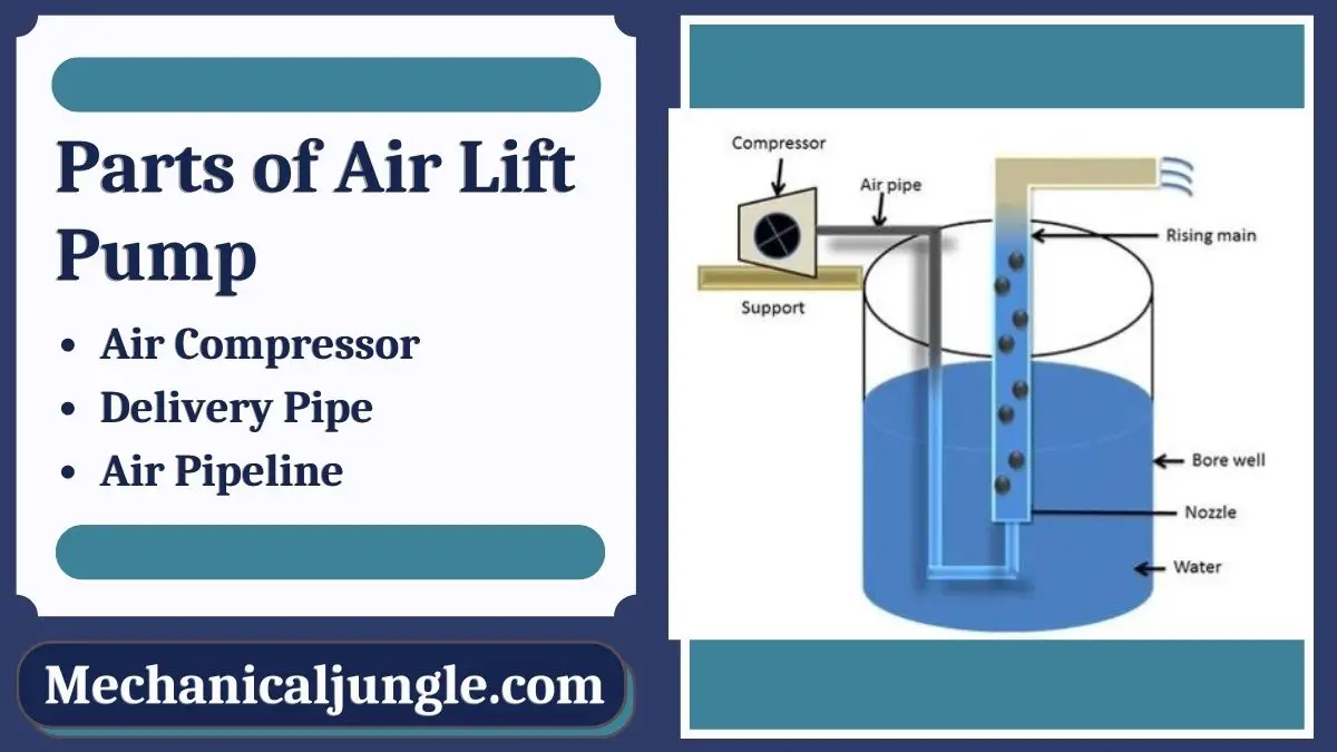
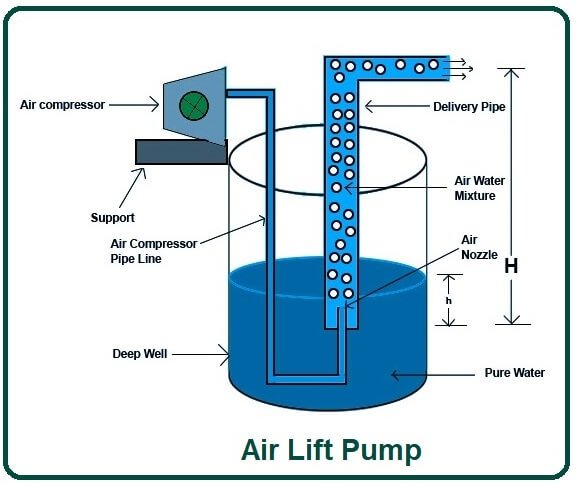
An air lift pumps are a device used to lift water from a well or a sump using compressed air. These pumps are also called mammoth pumps. Airlift pumps have been used since the early 20th century. The first airlift pump was invented in 1797 by German engineer Karl Emanuel Loscher. Air lift pumps are commonly found in agricultural land.
They are simple devices in which liquid enters from one end and a mixture of air and liquid discharge from the other end. Air is injected near the inlet. Almost without exceptions, the riser section of the airlift pumps has been a vertical pipe with a vertical cross-section.
Airlift pumps are typically used when maintenance needs to be kept to an absolute minimum. But this pump is not 100% maintenance-free because air is needed to deliver equipment to the pump that needs maintenance.
In air lift pumps, compressed air is mixed with water. We know that the density of water is much higher than the density of air. By buoyancy, the air that has a lower density than liquid rises quickly. By fluid pressure, the liquid is taken into the flow of the ascending air and moves in the same direction as the air.
The air is fed into the bottom of the riser pump, and this air freezes in water and form. As air mixes in water, the density of water decreases because the density of air and the mixture of water is less than the density of water.
So the mixture of air and water, also called froth, is much lower in density than water. Hence the main principle of air lift pump is the density difference between air and water mixture and water.
The velocity of the fluid through the pump and the velocity through the medium. The greater the difference between the respective velocities of fluid and air, the lower the overall efficiency of the pump.
For these pumps, the air injector system is in the form of an air jacket in which several holes are radially drilled through the pipe, and the air is supplied to them from the surrounding manifold.
An air pump is a device that uses the principles of gravity and inertia to move water by injecting a stream of compressed air into a pipe filled with a column of water.
An airlift pump is a pump that has low suction and moderate discharge of liquid and entrained solids. The pump injects compressed air into a pipe filled with a column of water.
The main advantage of the Husky double diaphragm air pump is that it can run dry for a limited time. A pump configuration in which the fluid source is located below the pump is called a pump stroke configuration. In other words, in a shock pump configuration, the pump draws from a fluid source located below the center line of the pump.
A major benefit of a Husky Air Operated Double Diaphragm pump is that it can run dry for a limited time. A pump layout in which the source of liquid is below the pump is called a suction lift configuration. In other words, in a suction lift configuration, a pump takes suction from a source of liquid located below the pump’s center line.

Jetting is useful for moving seabed soils for the burial of cables and pipelines and for installing instrument tubes and structural piles. Jetting is done by supplying pressurized water from a pump mounted on a surface-support platform. A variety of jetting mandrels and nozzles can be used, depending on the work to be done and the flow characteristics desired, such as width of jet and jet velocity.
In the simplest form of jetting, vast quantities of mud, sand, or silt can be moved by directing a high-velocity water stream, through a jet nozzle, at the material to be moved. The diver using the jet will have to provide resistance to the back thrust from the jet nozzle. Commercial nozzles are available that have balancing jets that reduce or eliminate the back thrust (Figure 236). A pump with a flow rate of about 100 gpm and a discharge pressure of between 50 and 150 psi over bottom pressure is adequate for this type of jetting operation.
• The first technique involves using large jets to erode and displace the seabed soil to leave an open trench. This method works well in many slightly or moderately consolidated cohesive soils (mud) as well as in some noncohesive (sandy) materials. The cable or pipeline to be buried is laid on the seafloor along the planned route. The jetted trench is then excavated either beneath or beside the cable or pipeline. The cable then either settles into place or is placed in the bottom of the trench.
sive) that have a flat natural slope (angle of repose). These conditions ordinarily would require removing large volumes of material. Many small jets are mounted on the leading edge of a plow-like stinger. The small jets erode and suspend the sand in front of the stinger. The cable to be buried is fed into the jetting area by a guide chute. The reduced density of the sandy soil allows the cable or pipeline to fall and become buried. The pump used for the fluid-ization jetting operation should have a flow rate of at least 500 gpm at a pressure of about 100 to 150 psi. See Sections 5.2 and 5.3 for more discussion of burial by jetting.
2.6.2.3 Structural Pile Installation. Jetting can be used for installing structural piles. Reinforced concrete piles may have a jet pipe built into the center of the pile. The water pump hose is connected to the top of the pile and the opening at the bottom of the pile tip serves as the nozzle. For all types of piles, a jet pipe is placed alongside the pile, with the tip of the pipe slightly below the bottom of the pile. The pile and jet pipe are lowered together as the jet displaces the soil below the pile. Usually the jet is removed before the pile reaches the specified penetration, and a hammer is used to drive the pile the final 5 feet or so to ensure that it has adequate bearing capacity. This method of pile installation is only effective in noncohesive (sandy) soils.
Underwater dredging is a useful technique for moving large quantities of soft seabed material where the water is too shallow for an air lift to be effective and where the material does not have to be lifted too far above the intake point. Figure 2-37 illustrates two underwater dredge arrangements. One system uses an eductor tube or pipe with a 30-degree bend near the intake end. At the center of the bend a water jet is connected. The water jet is aimed toward the discharge along the centerline of the main pipe. The jet moves the water in the pipe and creates a suction at the intake. The nozzle suction is created by the venturi principle and the height of the lift attained depends on the size of the pipe and the output of the pump. A 200-gpm pump with a 6-inch pipe will lift as high as 60 feet above the seabed. When operating only a few feet above die seabed this same system can move as much as 10 yd3 of loose gravel, mud, and sand per hour. Table 2-17 lists typical suction pipe, jet pipe, and pump sizes. Commercial eductor nozzles such as the gold dredge are listed in Appendix A.
Dredging is a process of excavation that uses specialized equipment—generally large suction pipes or dredges—to remove silt and other materials from the bottom of bodies of water. The material is usually deposited onto shorelines or near-shore areas to create new land or widen existing channels. The technology allows for the creation of new ports, harbors, and other waterways, as well as deepening or widening existing water channels. There are several different types of dredging vessels, each used for different purposes. Generally, the dredge will move along the bottom of the lake, river, or sea, using a combination of suction pumps, buckets, and conveyor belts to move sediment and other materials from the waterbed to a waiting barge or other transport. Different types of dredging vessels are used for different purposes, such as for mining, construction, reclamation, or even scientific research.
In some cases, the dredging process can involve pumping out the sediment from a body of water and then storing it elsewhere. This is often done to protect ecosystems or reduce the amount of sediment in the water. In other cases, the sediment is put back into the waterway, either in order to widen it or to create new land. In still other cases, the sediment is used to create artificial beaches or other forms of shoreline protection.
An airlift dredge is created by attaching a suction line to a dredge pipe and running it to a dredge pump. The dredge pump pulls water and sediment through the suction line, while air is injected into the suction line through air injectors. The air lifts the sediment and water up through the dredge pipe to the outlet of the dredge pump, where the sediment and water are discharged.
Use a submersible pump: A submersible pump is designed to pump water, sludge, and sand under the surface of the water. It operates on the same principle as a standard garden pump and can be used to transfer sand from one area to another.
An underwater gold dredge works by sucking up sediment from the bottom of a river or other body of water and then running it through a system which separates the gold from the other materials. The dredge consists of a power-driven pump connected to a long suction hose. The suction hose is then placed at the bottom of the body of water and held in place by an anchor. The pump then draws sediment and water through the hose and into the dredge. The sediment-water mix then passes through a series of tubes and sluices which are designed to allow the heavier gold particles to be captured while the lighter materials are discarded. The gold particles are then separated from the other materials and collected while the remaining waste is discarded.
Airlift dredging is a non-mechanical method of dredging that uses compressed air to create a down-ward suction. The air is injected into a pipe, which is submerged in the water and the air pressure pushes the sediment up the pipe and onto a conveyor belt, where it can be collected and disposed of. This method is used to clean up ponds, lakes, rivers, and other bodies of water.First, set up a submersible pump with a connecting pipe, and run it to the bottom of the waterway.
Attach the air pipe to a diaphragm pump. This will be used to pump air into the water below the platform, creating a bubble of air that will lift the platform up.
Start the air compressor and diaphragm pump to create an airlift. The bubble of air will cause the lifting force that is needed to raise the platform with the digging vessel attached.
Next, lower the suction head of the pump. This is the depth of water needed to lift the material through the suction hose or pipe. You"ll want to lower the suction head to the same depth as your forebay.
Suction pile installation typically involves a four-step process. First, a hole is bored into the seabed, usually with a jetting system, which uses a high-pressure jet of seawater to break up the seabed material. Then the suction piles are inserted into the hole to a predetermined depth. The piles are secured in place by the suction created by the installation pump, which pumps out water from the hole until the suction anchors the piles in place. Finally, the hole is backfilled with a grout material such as a concrete mix or a mix of sand and gravel.
To move underwater sand, you will need to use a device known as a sediment dredge. This device typically consists of a large suction pipe that is connected to a pump or tank. The pump or tank will then draw in the sediment and sand from the bottom of the water and will pump it into the desired location. This process is typically done by professional dredging services and can be done safely and efficiently to move undersea sand.
Air suction in a water line can be created by installing an air-injection system. This system uses a pump to inject air into the water line to create a vacuum, which pulls water through the line, causing the water to move faster and create suction. Additionally, you can increase suction by making sure that all the pipes in the system are clear of any obstructions or blockages, which can cause the water to be restricted and pressure to be lost.
A pump suction pipe works by using atmospheric pressure to draw liquid or gaseous substances into the suction pipe. The pressure within the suction pipe is lower than the atmospheric pressure, so a vacuum is created which draws the substance into the pipe. This vacuum is maintained by a check valve located at the bottom of the suction pipe, which prevents fluid from back flowing out of the pipe. The pump suction pipe also contains an inlet strainer to prevent any foreign objects from clogging the pump.
Gather the materials and supplies needed to build the underwater air lift. This includes PVC pipe, a long hose, several elbows, a siphon pump, a flexible pipe, several valves and water tanks.
Plan the route of the underwater air lift by plotting out the different locations of the pipes, valves and pumps on a map. Make sure to factor in any obstacles and curves in the air lift"s route.
A suction pile is a type of foundation used to support offshore structures, such as oil platforms. It works by creating a vacuum within the pile, causing the soil around it to become buoyant and lift up the structure. The vacuum is created by pumping air or water out of the bottom of the pile until the pressure within it is lower than the outside water pressure. This causes the soil to be forced up the sides of the pile and creates a suction force that holds the structure in place.
To make an air lift underwater, you will need a length of pipe, a compressor or air pump, and a valve.Connect the pipe to the compressor or air pump, and place the pipe into the water at the desired location.
A high-pressure water jetting system with an engine-driven vacuum is the most effective suction for water jetting. This system uses powerful pumps to generate suction and pressure, allowing the user to quickly and safely remove debris from narrow pipes and hard-to-reach areas. By combining the pressure of the water jet with the suction of the vacuum, the system can effectively clear clogs and remove a variety of material, including grease, silt, roots, and other materials.
A suction pipe works by using the pressure differential between the intake side and the discharge side of the pipe. The pressure differential causes a vacuum effect, allowing liquid or gas to be pulled through the pipe by suction. This is enabled by creating a situation where there is a higher pressure on the intake side of the pipe than on the discharge side. This can be achieved through varying configurations of pumps, valves, and other components to control the pressure differential.
Underwater suction pipes work by using a vacuum pump or an eductor to create a suction, which pulls water and suspended particles into a pipe. The pipe is then connected to a vacuum tank, which holds the collected material until it is ready to be removed. The vacuum tank is typically connected to a truck or boat, which transports the material for disposal, recycling, or further processing.
By Clifford E. Jones – There is no reason to pay a lot of money for a water pump when this DIY airlift pump design will do all you want. The cost is very low. The materials list is for a 100-foot well; adjust this to meet your well depth.
Now put the 1-1/4” clamp on top of the well cap. This will eventually keep the pump from dropping down the well, so make it tight and be sure it won’t slip down the hole in the well cap. Next, make the ½” line. Starting at the bottom, put on two 90 degree elbows and a 30” piece of pipe and insert it up into the 1-1-4” pipe and clamp both pipes together (Illustration 3).
What is happening here is air is pumped down the small pipe and released into the larger pipe forming bubbles which rise and capture the water and bring it to the top.
This article wouldn’t be complete without something on the air compressor. The main effort is to put some air down the small line that is only blocked by water. Any compressor capable of pumping up an auto tire will do. Air volume is more important than great pressure. I used an automobile air conditioner pump with great success but it did pump oil, and that isn’t good. Get yourself a good air compressor.
This airlift pump design may seem like a poor man’s pump, but there are some advantages over other pumps. It won’t freeze; you can do it yourself; any servicing is done at the compressor and not down the well; and if you just happen to live past the power company, you can still have the water and not cost you an arm and a leg.

There are many different ways to drill a domestic water well. One is what we call the “mud rotary” method. Whether or not this is the desired and/or best method for drilling your well is something more fully explained in this brief summary.
One advantage of drilling with compressed air is that it can tell you when you have encountered groundwater and gives you an indication how much water the borehole is producing. When drilling with water using the mud rotary method, the driller must rely on his interpretation of the borehole cuttings and any changes he can observe in the recirculating fluid. Mud rotary drillers can also use borehole geophysical tools to interpret which zones might be productive enough for your water well.
The mud rotary well drilling method is considered a closed-loop system. That is, the mud is cleaned of its cuttings and then is recirculated back down the borehole. Referring to this drilling method as “mud” is a misnomer, but it is one that has stuck with the industry for many years and most people understand what the term actually means.
The water is carefully mixed with a product that should not be called mud because it is a highly refined and formulated clay product—bentonite. It is added, mixed, and carefully monitored throughout the well drilling process.
The purpose of using a bentonite additive to the water is to form a thin film on the walls of the borehole to seal it and prevent water losses while drilling. This film also helps support the borehole wall from sluffing or caving in because of the hydraulic pressure of the bentonite mixture pressing against it. The objective of the fluid mixture is to carry cuttings from the bottom of the borehole up to the surface, where they drop out or are filtered out of the fluid, so it can be pumped back down the borehole again.
When using the mud rotary method, the driller must have a sump, a tank, or a small pond to hold a few thousand gallons of recirculating fluid. If they can’t dig sumps or small ponds, they must have a mud processing piece of equipment that mechanically screens and removes the sands and gravels from the mixture. This device is called a “shale shaker.”
The driller does not want to pump fine sand through the pump and back down the borehole. To avoid that, the shale shaker uses vibrating screens of various sizes and desanding cones to drop the sand out of the fluid as it flows through the shaker—so that the fluid can be used again.
Some drillers use compressed air to blow off the well, starting at the first screened interval and slowly working their way to the bottom—blowing off all the water standing above the drill pipe and allowing it to recover, and repeating this until the water blown from the well is free of sand and relatively clean. If after repeated cycles of airlift pumping and recovery the driller cannot find any sand in the water, it is time to install a well development pump.
Additional development of the well can be done with a development pump that may be of a higher capacity than what the final installation pump will be. Just as with cycles of airlift pumping of the well, the development pump will be cycled at different flow rates until the maximum capacity of the well can be determined. If the development pump can be operated briefly at a flow rate 50% greater than the permanent pump, the well should not pump sand.
Mud rotary well drillers for decades have found ways to make this particular system work to drill and construct domestic water wells. In some areas, it’s the ideal method to use because of the geologic formations there, while other areas of the country favor air rotary methods.
To learn more about the difference between mud rotary drilling and air rotary drilling, click the video below. The video is part of our “NGWA: Industry Connected” YouTube series:
An air lift pumps are a device used to lift water from a well or a sump using compressed air. These pumps are also called mammoth pumps. Airlift pumps have been used since the early 20th century. The first airlift pump was invented in 1797 by German engineer Karl Emanuel Loscher. Air lift pumps are commonly found in agricultural land.
They are simple devices in which liquid enters from one end and a mixture of air and liquid discharge from the other end. Air is injected near the inlet. Almost without exceptions, the riser section of the airlift pumps has been a vertical pipe with a vertical cross-section.
Airlift pumps are typically used when maintenance needs to be kept to an absolute minimum. But this pump is not 100% maintenance-free because air is needed to deliver equipment to the pump that needs maintenance.
In air lift pumps, compressed air is mixed with water. We know that the density of water is much higher than the density of air. By buoyancy, the air that has a lower density than liquid rises quickly. By fluid pressure, the liquid is taken into the flow of the ascending air and moves in the same direction as the air.
The air is fed into the bottom of the riser pump, and this air freezes in water and form. As air mixes in water, the density of water decreases because the density of air and the mixture of water is less than the density of water.
So the mixture of air and water, also called froth, is much lower in density than water. Hence the main principle of air lift pump is the density difference between air and water mixture and water.
The velocity of the fluid through the pump and the velocity through the medium. The greater the difference between the respective velocities of fluid and air, the lower the overall efficiency of the pump.
For these pumps, the air injector system is in the form of an air jacket in which several holes are radially drilled through the pipe, and the air is supplied to them from the surrounding manifold.
An air pump is a device that uses the principles of gravity and inertia to move water by injecting a stream of compressed air into a pipe filled with a column of water.
An airlift pump is a pump that has low suction and moderate discharge of liquid and entrained solids. The pump injects compressed air into a pipe filled with a column of water.
The main advantage of the Husky double diaphragm air pump is that it can run dry for a limited time. A pump configuration in which the fluid source is located below the pump is called a pump stroke configuration. In other words, in a shock pump configuration, the pump draws from a fluid source located below the center line of the pump.
A major benefit of a Husky Air Operated Double Diaphragm pump is that it can run dry for a limited time. A pump layout in which the source of liquid is below the pump is called a suction lift configuration. In other words, in a suction lift configuration, a pump takes suction from a source of liquid located below the pump’s center line.

Jetting is useful for moving seabed soils for the burial of cables and pipelines and for installing instrument tubes and structural piles. Jetting is done by supplying pressurized water from a pump mounted on a surface-support platform. A variety of jetting mandrels and nozzles can be used, depending on the work to be done and the flow characteristics desired, such as width of jet and jet velocity.
In the simplest form of jetting, vast quantities of mud, sand, or silt can be moved by directing a high-velocity water stream, through a jet nozzle, at the material to be moved. The diver using the jet will have to provide resistance to the back thrust from the jet nozzle. Commercial nozzles are available that have balancing jets that reduce or eliminate the back thrust (Figure 236). A pump with a flow rate of about 100 gpm and a discharge pressure of between 50 and 150 psi over bottom pressure is adequate for this type of jetting operation.
• The first technique involves using large jets to erode and displace the seabed soil to leave an open trench. This method works well in many slightly or moderately consolidated cohesive soils (mud) as well as in some noncohesive (sandy) materials. The cable or pipeline to be buried is laid on the seafloor along the planned route. The jetted trench is then excavated either beneath or beside the cable or pipeline. The cable then either settles into place or is placed in the bottom of the trench.
sive) that have a flat natural slope (angle of repose). These conditions ordinarily would require removing large volumes of material. Many small jets are mounted on the leading edge of a plow-like stinger. The small jets erode and suspend the sand in front of the stinger. The cable to be buried is fed into the jetting area by a guide chute. The reduced density of the sandy soil allows the cable or pipeline to fall and become buried. The pump used for the fluid-ization jetting operation should have a flow rate of at least 500 gpm at a pressure of about 100 to 150 psi. See Sections 5.2 and 5.3 for more discussion of burial by jetting.
2.6.2.3 Structural Pile Installation. Jetting can be used for installing structural piles. Reinforced concrete piles may have a jet pipe built into the center of the pile. The water pump hose is connected to the top of the pile and the opening at the bottom of the pile tip serves as the nozzle. For all types of piles, a jet pipe is placed alongside the pile, with the tip of the pipe slightly below the bottom of the pile. The pile and jet pipe are lowered together as the jet displaces the soil below the pile. Usually the jet is removed before the pile reaches the specified penetration, and a hammer is used to drive the pile the final 5 feet or so to ensure that it has adequate bearing capacity. This method of pile installation is only effective in noncohesive (sandy) soils.
Underwater dredging is a useful technique for moving large quantities of soft seabed material where the water is too shallow for an air lift to be effective and where the material does not have to be lifted too far above the intake point. Figure 2-37 illustrates two underwater dredge arrangements. One system uses an eductor tube or pipe with a 30-degree bend near the intake end. At the center of the bend a water jet is connected. The water jet is aimed toward the discharge along the centerline of the main pipe. The jet moves the water in the pipe and creates a suction at the intake. The nozzle suction is created by the venturi principle and the height of the lift attained depends on the size of the pipe and the output of the pump. A 200-gpm pump with a 6-inch pipe will lift as high as 60 feet above the seabed. When operating only a few feet above die seabed this same system can move as much as 10 yd3 of loose gravel, mud, and sand per hour. Table 2-17 lists typical suction pipe, jet pipe, and pump sizes. Commercial eductor nozzles such as the gold dredge are listed in Appendix A.
Dredging is a process of excavation that uses specialized equipment—generally large suction pipes or dredges—to remove silt and other materials from the bottom of bodies of water. The material is usually deposited onto shorelines or near-shore areas to create new land or widen existing channels. The technology allows for the creation of new ports, harbors, and other waterways, as well as deepening or widening existing water channels. There are several different types of dredging vessels, each used for different purposes. Generally, the dredge will move along the bottom of the lake, river, or sea, using a combination of suction pumps, buckets, and conveyor belts to move sediment and other materials from the waterbed to a waiting barge or other transport. Different types of dredging vessels are used for different purposes, such as for mining, construction, reclamation, or even scientific research.
In some cases, the dredging process can involve pumping out the sediment from a body of water and then storing it elsewhere. This is often done to protect ecosystems or reduce the amount of sediment in the water. In other cases, the sediment is put back into the waterway, either in order to widen it or to create new land. In still other cases, the sediment is used to create artificial beaches or other forms of shoreline protection.
An airlift dredge is created by attaching a suction line to a dredge pipe and running it to a dredge pump. The dredge pump pulls water and sediment through the suction line, while air is injected into the suction line through air injectors. The air lifts the sediment and water up through the dredge pipe to the outlet of the dredge pump, where the sediment and water are discharged.
Use a submersible pump: A submersible pump is designed to pump water, sludge, and sand under the surface of the water. It operates on the same principle as a standard garden pump and can be used to transfer sand from one area to another.
An underwater gold dredge works by sucking up sediment from the bottom of a river or other body of water and then running it through a system which separates the gold from the other materials. The dredge consists of a power-driven pump connected to a long suction hose. The suction hose is then placed at the bottom of the body of water and held in place by an anchor. The pump then draws sediment and water through the hose and into the dredge. The sediment-water mix then passes through a series of tubes and sluices which are designed to allow the heavier gold particles to be captured while the lighter materials are discarded. The gold particles are then separated from the other materials and collected while the remaining waste is discarded.
Airlift dredging is a non-mechanical method of dredging that uses compressed air to create a down-ward suction. The air is injected into a pipe, which is submerged in the water and the air pressure pushes the sediment up the pipe and onto a conveyor belt, where it can be collected and disposed of. This method is used to clean up ponds, lakes, rivers, and other bodies of water.First, set up a submersible pump with a connecting pipe, and run it to the bottom of the waterway.
Attach the air pipe to a diaphragm pump. This will be used to pump air into the water below the platform, creating a bubble of air that will lift the platform up.
Start the air compressor and diaphragm pump to create an airlift. The bubble of air will cause the lifting force that is needed to raise the platform with the digging vessel attached.
Next, lower the suction head of the pump. This is the depth of water needed to lift the material through the suction hose or pipe. You"ll want to lower the suction head to the same depth as your forebay.
Suction pile installation typically involves a four-step process. First, a hole is bored into the seabed, usually with a jetting system, which uses a high-pressure jet of seawater to break up the seabed material. Then the suction piles are inserted into the hole to a predetermined depth. The piles are secured in place by the suction created by the installation pump, which pumps out water from the hole until the suction anchors the piles in place. Finally, the hole is backfilled with a grout material such as a concrete mix or a mix of sand and gravel.
To move underwater sand, you will need to use a device known as a sediment dredge. This device typically consists of a large suction pipe that is connected to a pump or tank. The pump or tank will then draw in the sediment and sand from the bottom of the water and will pump it into the desired location. This process is typically done by professional dredging services and can be done safely and efficiently to move undersea sand.
Air suction in a water line can be created by installing an air-injection system. This system uses a pump to inject air into the water line to create a vacuum, which pulls water through the line, causing the water to move faster and create suction. Additionally, you can increase suction by making sure that all the pipes in the system are clear of any obstructions or blockages, which can cause the water to be restricted and pressure to be lost.
A pump suction pipe works by using atmospheric pressure to draw liquid or gaseous substances into the suction pipe. The pressure within the suction pipe is lower than the atmospheric pressure, so a vacuum is created which draws the substance into the pipe. This vacuum is maintained by a check valve located at the bottom of the suction pipe, which prevents fluid from back flowing out of the pipe. The pump suction pipe also contains an inlet strainer to prevent any foreign objects from clogging the pump.
Gather the materials and supplies needed to build the underwater air lift. This includes PVC pipe, a long hose, several elbows, a siphon pump, a flexible pipe, several valves and water tanks.
Plan the route of the underwater air lift by plotting out the different locations of the pipes, valves and pumps on a map. Make sure to factor in any obstacles and curves in the air lift"s route.
A suction pile is a type of foundation used to support offshore structures, such as oil platforms. It works by creating a vacuum within the pile, causing the soil around it to become buoyant and lift up the structure. The vacuum is created by pumping air or water out of the bottom of the pile until the pressure within it is lower than the outside water pressure. This causes the soil to be forced up the sides of the pile and creates a suction force that holds the structure in place.
To make an air lift underwater, you will need a length of pipe, a compressor or air pump, and a valve.Connect the pipe to the compressor or air pump, and place the pipe into the water at the desired location.
A high-pressure water jetting system with an engine-driven vacuum is the most effective suction for water jetting. This system uses powerful pumps to generate suction and pressure, allowing the user to quickly and safely remove debris from narrow pipes and hard-to-reach areas. By combining the pressure of the water jet with the suction of the vacuum, the system can effectively clear clogs and remove a variety of material, including grease, silt, roots, and other materials.
A suction pipe works by using the pressure differential between the intake side and the discharge side of the pipe. The pressure differential causes a vacuum effect, allowing liquid or gas to be pulled through the pipe by suction. This is enabled by creating a situation where there is a higher pressure on the intake side of the pipe than on the discharge side. This can be achieved through varying configurations of pumps, valves, and other components to control the pressure differential.
Underwater suction pipes work by using a vacuum pump or an eductor to create a suction, which pulls water and suspended particles into a pipe. The pipe is then connected to a vacuum tank, which holds the collected material until it is ready to be removed. The vacuum tank is typically connected to a truck or boat, which transports the material for disposal, recycling, or further processing.


 8613371530291