
calculate mud pump efficiency in stock
Rig pump output, normally in volume per stroke, of mud pumps on the rig is one of important figures that we really need to know because we will use pump out put figures to calculate many parameters such as bottom up strokes, wash out depth, tracking drilling fluid, etc. In this post, you will learn how to calculate pump out put for triplex pump and duplex pump in bothOilfield and Metric Unit.

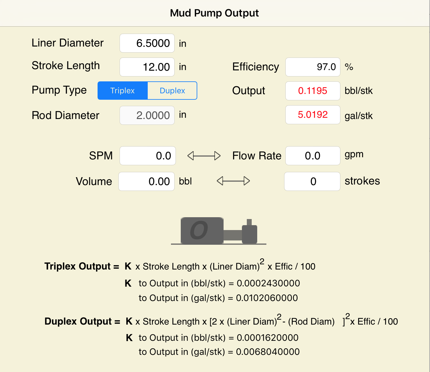
Pump Output per Stroke (PO): The calculator returns the pump output per stroke in barrels (bbl). However this can be automatically converted to other volume units (e.g. gallons or liters) via the pull-down menu.
A triplex mud (or slush) pump has three horizontal plungers (cylinders) driven off of one crankshaft. Triplex mud pumps are often used for oil drilling.

Oil and Gas drilling process - Pupm output for Triplex and Duplex pumpsTriplex Pump Formula 1 PO, bbl/stk = 0.000243 x ( in) E.xample: Determine the pump output, bbl/stk, at 100% efficiency for a 7" by 12". triplex pump: PO @ 100%,= 0.000243 x 7 x12 PO @ 100% = 0.142884bbl/stk Adjust the pump output for 95% efficiency: Decimal equivalent = 95 + 100 = 0.95 PO @ 95% = 0.142884bbl/stk x 0.95 PO @ 95% = 0.13574bbl/stk Formula 2 PO, gpm = [3(D x 0.7854)S]0.00411 x SPM where D = liner diameter, in. S = stroke length, in. SPM = strokes per minute Determine the pump output, gpm, for a 7" by 12". triplex pump at 80 strokes per minute: PO, gpm = [3(7 x 0.7854) 1210.00411 x 80 PO, gpm = 1385.4456 x 0.00411 x 80 PO = 455.5 gpm
Example:Duplex Pump Formula 1 0.000324 x (liner diameter, in) x ( stroke lengh, in) = ________ bbl/stk -0.000162 x (rod diameter, in) x ( stroke lengh, in) = ________ bbl/stk Pump out put @ 100% eff = ________bbl/stk Example: Determine the output, bbl/stk, of a 5 1/2" by 14" duplex pump at 100% efficiency. Rod diameter = 2.0": 0.000324 x 5.5 x 14 = 0.137214bbl/stk -0.000162 x 2.0 x 14 = 0.009072bbl/stk Pump output @ 100% eff. = 0.128142bbl/stk Adjust pump output for 85% efficiency: Decimal equivalent = 85 100 = 0.85 PO@85%)= 0.128142bbl/stk x 0.85 PO@ 85% = 0.10892bbl/stk Formula 2
PO. bbl/stk = 0.000162 x S[2(D) - d] where S = stroke length, in. D = liner diameter, in. d = rod diameter, in. Example: Determine the output, bbl/stk, of a 5 1/2". by 14". duplex pump @ 100% efficiency. Rod diameter = 2.0in.: PO@100%=0.000162 x 14 x [ 2 (5.5) - 2 ] PO @ 100%)= 0.000162 x 14 x 56.5 PO@ 100%)= 0.128142bbl/stk Adjust pump output for 85% efficiency: PO@85%,= 0.128142bb/stkx 0.85 PO@8.5%= 0.10892bbl/stk Metric calculation Pump output, liter/min = pump output. liter/stk x pump speed, spm. S.I. units calculation Pump output, m/min = pump output, liter/stk x pump speed, spm. Mud Pumps Mud pumps drive the mud around the drilling system. Depending on liner size availability they can be set up to provide high pressure and low flow rate, or low pressure and high flow rate. Analysis of the application and running the Drill Bits hydraulics program will indicate which liners to recommend. Finding the specification of the mud pumps allows flow rate to be calculated from pump stroke rate, SPM. Information requiredo Pump manufacturer o Number of pumps o Liner size and gallons per revolution Weight As a drill bit cutting structure wears more weight will be required to achieve the same RoP in a homogenous formation. PDC wear flats, worn inserts and worn milled tooth teeth will make the bit drill less efficiently. Increase weight in increments of 2,000lbs approx. In general, weight should be applied before excessive rotary speed so that the cutting structure maintains a significant depth of cut to stabilise the bit and prevent whirl. If downhole weight measurements are available they can be used in combination with surface measurements to gain a more accurate representation of what is happening in the well bore.

NOTE: Max RPM in the above equation varies according to type of pump, size of stroke, and other variables. Duplex pumps often run about 100 RPM Max. while triplex pumps will run somewhere between 100 RPM Max and 400 RPM Max.
I have a reciprocating pump and I know what my max rated rod load is (in foot pounds). I also know what size plunger size my pump has. What PSI will my pump produce?
Specific Gravity is used when sizing a centrifugal pump. Liquids with a specific gravity greater than 1.0 are heavier than water and conversely, liquids with a specific gravity lower than 1.0 are lighter weight than water and will generally float on water.

This worksheet takes inputs for the rig pumps and (optionally) hole and pipe sizes. It outputs pump flow rates and power, also fluid velocity if diameters entered.

The ratio of the actual output volume of a positive displacement pump divided by the theoretical geometric maximum volume of liquid that the pump could output under perfect conditions. Inefficiencies are caused by gaseous components (air and methane) being trapped in the liquid mud, leaking and noninstantaneously sealing valves in the pumps, fluid bypass of pump swab seals, and mechanical clearances and "play" in various bearings and connecting rods in the pumps. This efficiency is usually expressed as a percentage, and ranges from about 92% to 99% for most modern rig pumps and cement pumps. For critical calculations, this efficiency can be determined by a rigsite version of the "bucket and stopwatch" technique, whereby the rig crew will count the number of pump strokes required to pump a known volume of fluid. In cementing operations, displacement is often measured by alternating between two 10-bbl displacement tanks.

I am often asked if the viscosity of the drilling fluid affects the efficiency of a positive displacement, single-acting, reciprocating pump. There is no easy answer. When trying to calculate efficiency, a number of factors are to be considered.
Most drill pumps either triplex (three cylinder) or quintuplex (five cylinder) pumps in the horizontal directional drilling industry are single-acting pumps — meaning they have no means of priming or feeding themselves. When the piston is moving in the opposite direction of discharge, this is referred to as the suction stroke. This is misleading, but it is a way to differentiate between the discharge stroke and the filling of the pumping chamber or suction stroke.
A single-acting pump relies on atmospheric and head pressure to fill the pumping chamber with liquid before the rotation of the crankshaft starts the piston in forward motion to discharge a particular cylinder. At the beginning of the suction cycle, a pumping cylinder has been emptied and the suction and discharge valves are closed. The cylinder has been evacuated of liquid and that cylinder has gone from line pressure to almost zero pressure. Atmospheric and head pressure, being greater than the pressure within the pumping cylinder, forces the suction valve to lift or open. Liquid flows through the throat of the seat, fills the chamber and then the suction valve closes. At this point both the suction and discharge valve assemblies are closed, awaiting the forward movement of the piston.
Most pumps fitted on drill rigs in the HDD industry tend to be smaller in size and weight to facilitate easier movement of the equipment and to lower the overall cost of the rig. Consequently, they tend to operate at a higher rate of speed than a pump used in continuous service. Since the overall size of the pump is smaller, the liquid end and associated expendables will also be smaller.
The suction seat can be considered nothing more than an orifice or restriction in the flow of the liquid to a particular pumping cylinder. It takes a given amount of time for water to flow through the throat of the suction seat before the beginning of the discharge stroke. As the viscosity of the slurry mix increases, it takes more time for the slurry to flow through the throat of the suction seat at a given pump rpm. As the liquid is passing through the throat of the suction seat, entrained oxygen can and will break out of solution if the liquid column is moving faster than the net open area of the suction seat can accommodate. The pumping chamber will become partially filled with air bubbles. If the pumping chamber is not filled with fluid, this induces cavitation within the pumping cylinder and is detrimental to the entire pump and associated piping. Also, volumetric efficiency of the pump will be reduced. Therefore, the net open seat area is important to any pump at any speed. However, if you choose to physically fill a pumping cylinder with an extremely viscous liquid, the chamber will be evacuated at the end of the discharge stroke. Hence, the chamber was emptied and the pump was 100 percent efficient on that particular discharge stroke.
If the system is closed — meaning the inlet to the pump has positive pressure by the use of a centrifugal pump — the design of the suction system is still important. Most pump problems are related to the suction side of the pump. The piping should be short, large in inside diameter and straight. There needs to be as few restrictions or bends within the suction line as possible. The entire column of fluid traveling to the pump should have a velocity of no less than 1 ft per second and no greater than 3 ft. Even within a charged system, the liquid within the line has to accelerate and decelerate with each opening/closing of a suction valve. A charge pump cannot overcome a poorly designed suction system nor can it overcome excessive pump rpm.
The case can be made that as fluid viscosity increases, the efficiency of the pump decreases. That is only a true statement if the drilling slurry cannot pass through the suction seat and fill the pumping chamber before the rotation of the crankshaft starts a discharge stroke on any given pumping chamber.
Ron Lowe is a marketing representative with Myers-Aplex, a Pentair Pump company. All Drillmaster Reports are reviewed by the Drillmaster Advisory Board: Lowe; Frank Canon, Baroid Industrial Drilling Products; Richard Levings, Ditch Witch; Dan Miller, Digital Control Inc.; and Ed Savage, Vermeer Mfg. Co.

Electronic Pump Stroke Counters are a vital part to any drilling rig operation. When a mud pump is in operation, the driller must know how much mud is flowing down hole in order to keep the operation running at peak efficiency. Pump stroke counters assist the driller by measuring the mud pump’s strokes per minute and total strokes. So, how does a pump stroke counter tally the mud pump’s strokes
Electronic Pump Stroke Counters are a vital part to any drilling rig operation. When a mud pump is in operation, the driller must know how much mud is flowing down hole in order to keep the operation running at peak efficiency. Pump stroke counters assist the driller by measuring the mud pump’s strokes per minute and total strokes. So, how does a pump stroke counter tally the mud pump’s strokes, and why it is important? In order to understand that, you’ll need to know some basic information about mud pumps.
Knowing how a mud pump functions is important in understanding the role a pump stroke counter plays in rig operations. Mud pumps act as the heart of the drilling rig, similar to how our heart works. Just as our heart circulates blood throughout our bodies, a mud pump circulates essential drilling mud down the hole and back up to the surface. Mud tanks house drilling mud, and a mud pump draws the fluid from the mud pump. A piston draws mud in on the backstroke through the open intake valve and pushes mud through the discharge valve and sends it towards the rig. By circulating fluid, the mud pump ensures that the drill bit is cool and lubricated and that cuttings are flushed from the hole. The two main kinds of pumps used are duplex and triplex pumps, where the duplex pump has two pistons and the triplex pump has three. Whether the rig is using a duplex or triplex pump, it is important to know how many strokes per second the pistons are moving. The driller monitors strokes per minute to determine how much costly, yet essential, mud is being pumped into the system with the use of a mud pump stroke counter system. Now, that you know about mud pumps, you’ll need to know what’s in a stroke counter system.
Stroke Counter — The stroke counter stainless steel box is mounted on the driller’s console and is either square or rectangular in shape, depending on the number of pumps it is monitoring. Stroke counters will show strokes per minute and total strokes, and when a particular mud pump is operating the strokes/minute and total strokes will be displayed. Power is supplied by a 3.6 volt lithium battery, and the counter contains a crystal-controlled real time clock with 100 parts per million accuracy or better. Each counter is mounted to the console with 1/4” stainless steel hex head bolts, lock washers and nuts.
Micro Limit Switch — The micro switch is connected to a c clamp near the mud pump piston. The micro switch stainless steel rod (sometimes called a whisker) sticks out in the piston housing near the piston. As the piston passes the rod, it moves the rod and the switch sends an electronic signal back to the counter. The counter increases by one each time the piston moves the rod, counting the mud pump’s strokes. The switch’s signal is then transmitted to the stroke counter. These micro switches are built to stand up to demanding outdoor conditions. They can withstand shock, equipment vibration, extreme temperatures, water and dust.
Cable and Junction Box – A cable is connected to the back of the pump stroke counter and then to the junction box. From the junction box, the cables travel to the limit switches.
Pump Stroke Counters are like a blood pressure machine. Each time our heart pumps, a blood pressure machine reads our systolic and diastolic blood pressure by way of our pulse. A mud pump stroke counter functions in much the same way. Just as a blood pressure machine detects our pulse so too does a limit switch rod detect the movement of the piston. When the stainless steel rod is moved, the micro limit switch detects the movement. The signal is sensed as a contact closure, and it is transmitted to the stroke counter where the contact closure is converted to a logic pulse. The pulse feeds two separate circuits. The total strokes circuit reads and displays the closures one at a time, totaling them up to reveal the total strokes in the LED window. The second pulse is sent along a separate circuit which is a rate circuit. This rate circuit will average the closures against the real time clock. The result is displayed as the total strokes per minute.
Pump stroke counters are essential to drilling rig operations because they measure the efficiency of mud pumps. Knowing strokes per minute and total strokes of the pistons helps the driller to determine if the correct amount of mud is going down hole. Having this information aids in running a drilling rig at peak efficiency, assists in extending drill bit life, and avoids costly overuse of drilling rig mud. Unsure which pump stroke counter is right for your application? Give our friendly, knowledgeable staff a call or email. We’ll keep you turning right.

Browse through more than 1,500 duplex piston rods and 200 duplex pony rods in our inventory. EC Tool gives you a quote before your order, so you know what you’re getting for your money every time. While we primarily keep connecting rods for GA550 and GA750 models in stock, there are other options at your disposal as well. This includes custom connecting rods for most duplex and triplex mud pumps.
We now offer new crossheads and capsules for both EMSCO D-375 and DB-550 duplex pumps. You can also find slides and shoes for certain models. Available parts currently in our inventory include:


 8613371530291