
cost per day to operate a mud pump free sample

A well-placed suction stabilizer can also prevent pump chatter. Pump chatter occurs when energy is exchanged between the quick opening and closing of the reciprocating pump’s valves and the hammer effect from the centrifugal pump. Pump isolation with suction stabilizers is achieved when the charge pumps are isolated from reciprocating pumps and vice versa. The results are a smooth flow of pumped media devoid of agitating energies present in the pumped fluid.
Suction stabilizer units can mitigate most of the challenges related to pulsations or pressure surges, even in the most complex piping conditions. The resulting benefits prevent expensive unplanned downtime and decrease costs and inconvenience associated with system replacements and repairs.

If you ended up on this page doing normal allowed operations, please contact our support at support@mdpi.com. Please include what you were doing when this page came up and the Ray ID & Your IP found at the
OK, all y’all air drillers just thumb on over to Porky’s column or something. This is for mud drillers. On second thought, I know a lot of you air guys drill about three mud wells a year, and consider it a hassle to rig up mud. So, maybe something I say will be interesting …
The mud pump is the heart of the circulating system, and mud is the blood circulating in the hole. I’ve talked about mud before and will again, but this month, let’s talk about the pump.
Historically, more wells, of every kind, have been drilled with duplex pumps than any other kind. They are simple and strong, and were designed in the days when things were meant to last. Most water well drillers use them. The drawbacks are size and weight. A pump big enough to do the job might be too big to fit on the rig, so some guys use skid-mounted pumps. They also take a fair amount of horsepower. If you were to break down the horsepower requirements of your rig, you would find out that the pump takes more power than the rotary and hoist combined. This is not a bad thing, since it does a lot of the work drilling. While duplex pumps generally make plenty of volume, one of the limiting factors is pressure. Handling the high pressures demanded by today’s oil well drilling required a pump so big and heavy as to be impractical. Some pretty smart guys came up with the triplex pump. It will pump the same — or more — volume in a smaller package, is easy to work on and will make insane pressure when needed. Some of the modern frack outfits run pumps that will pump all day long at 15,000 psi. Scary. Talk about burning some diesel.
The places that triplex pumps have in the shallow drilling market are in coring and air drilling. The volume needs are not as great. For instance, in hard rock coring, surface returns are not always even seen, and the fluid just keeps the diamonds cool. In air drilling, a small triplex is used to inject foam or other chemicals into the air line. It’s basically a glorified car wash pump. The generic name is Bean pump, but I think this just justifies a higher price. Kinda like getting the same burger at McDonald’s versus in a casino.
One of the reasons water well drillers don’t run triplex pumps, besides not needing insane pressure, is they require a positive suction head. In other words, they will not pick up out of the pit like a duplex. They require a centrifugal charging pump to feed them, and that is just another piece of equipment to haul and maintain.
This brings me to another thought: charging. I know a lot of drillers running duplex pumps that want to improve the efficiency of their pumps. Duplexes with a negative suction head generally run at about 85 percent efficiency. The easy way to improve the efficiency is to charge them, thus assuring a 100 percent efficiency. This works great, but almost every one of them, after doing all that work and rigging up a charging pump, tells me that their pump output doubled. Being the quiet, mild mannered type that I am, I don’t say “Bull,” but it is. A duplex pump is a positive displacement pump. That means that it can deliver no more than the displacement it was designed for. You can only fill the cylinder up until it is full. It won’t take any more. The one exception to this is when you are pumping at very low pressure. Then the charging pump will over run the duplex, float the valves and produce a lot more fluid. Might as well shut off the duplex and drill with the charging pump.
Another common pump used in the water well industry is the centrifugal. You see them mostly on air rigs that don’t use mud too often. They have their place, but are a different breed of cat. They are not positive displacement. Flow is a function of speed and horsepower up to the limits of the pump. After that, they just dead-head. With large diameter drill pipe they make a lot of mud, but after the hole gets deeper, friction losses — both inside and outside the drill pipe — build up. This means that the deeper you go, the less circulation you have. This slows the whole process. Positive displacement pumps don’t do this; they pump the same per stroke regardless of pressure. It just takes more horsepower. Also, displacement calculations like bottoms-up time and cement placement are just about impossible. One way to get around the limited pressure of centrifugal pumps is to run two of them in series. I’ve seen a few of these rig-ups and they work very well for large diameter drilling. They will make almost the same pressure as a big duplex for a lot less money. They are still variable displacement, but they roll so much fluid that it doesn’t seem to matter. And run at pretty reasonable depths, too: 300 to 400 psi at 400 gpm is not uncommon with two 3 x 4 centrifugal pumps in series.
I reckon there are pumps for every type of drilling. It is just a matter of using the right one correctly. I once drilled a 42-inch hole 842 feet deep with a 5½ x 8 duplex. Talk about long bottoms-up time … but we got the casing in with less than two feet of fill on bottom! Took time, but we got-er-done.

Mud pumps are a vital part of pipeline drilling projects. But with mud pumps, you have a decision to make: Should you use an onboard or a stand-alone mud pump? Both can get the job done well, but what’s the best option for your operation? To answer those questions, we have to look at three different factors: productivity, transportation and space.
First, you have to consider your productivity goals. To maximise the capacity and productivity of your pipeline directional drills, you need a consistent flow of drilling fluid that a mud pump can provide. However, there is a difference in size between onboard mud pumps and stand-alone ones.
For example, on the Vermeer D220x300 S3 Navigator® horizontal directional drill the maximum drilling fluid flow is 345 gal./min (1306 l/min). An onboard mud pump most likely won’t be able to reach that maximum flow but a stand-alone pump could. At 100% efficiency, the Vermeer SA400 Tier 4i (Stage IIIB) high-pressure mud pump has a maximum flow of 550 gal./min (2082 l/min), which would allow you to maximise the fluid flow on your drill.
If you lower your fluid flow, you are slowing your downhole speed and your thrust/pullback speed. You can get by with a smaller onboard mud pump, but you will have to take things slower and be patient as you drill.
“The higher the flow, the higher the productivity,” said Tod Michael, a Vermeer product manager for trenchless products. “If you are drilling a smaller diameter bore, a small onboard pump could handle the job. But if you need to increase your fluid, have a higher gal/min flow downhole or are drilling a 24 in. (60.9 cm) diameter or larger, a stand-alone mud pump is a good option.”
A stand-alone mud pump means there is more equipment to haul to the jobsite. Often, this requires an additional truck to transport it, since you also have to haul your drill, reclaimer and drilling fluid too. Another truck means extra costs and is something to be aware of beforehand.
“I would advise weighing the transportation costs with your productivity advantage,” suggested Michael. “If you find you can live with lower productivity because it’s more economical to haul only one truck, that’s great. If you find it’s better to haul two trucks of equipment to maximise your productivity, that is great too. It all comes down to your preference and your specific operation.”
One last thing to consider before you make a decision between onboard or stand-alone mud pumps is the space on the jobsite. Think about the typical amount of room you have for equipment. Will you have space for a stand-alone mud pump each time?
“Your jobsite space may vary from site to site, but ensuring that you will have room for a mud pump is an important factor to remember as you plan the project,” said Michael. “Usually, if contractors have the space, they will opt to have a stand-alone mud pump onsite.”
At the end of the day, the decision is yours. Considering the productivity pros and cons, the additional transport costs and the space on your jobsite can help make the decision simpler but it all depends on your specific needs and how you operate on a daily basis.

Usually it is necessary to pump every day until displacement depending on the pit size. Generally this would mean about five days of pumping pit fluid and cuttings prior to mud up. Once mud up occurs the pump will run about every other day through out the rest of the well. So for example, a 12 day well, would have 8 days pumping and 4 standby days for a total of $4,560.
Additionally, there would be approximately 100 gallons of diesel consumed at approximately $3 per gallon for $300. Set up and tear down is a total of $750 and average mileage would run an estimated $200. Typically overnight charges would be required for 5 nights which would be $375. Total pump charge for a typical well would be approximately $6,185.

This paper focuses on the operational experience that was gained during field test of the Hex Pump on a land rig in Jasper, Texas in October 2003. This field test showed that the pulsation frequency in the flow from the Hex Pump did not interfere with the MWD-measurements, providing a much cleaner signal to the directional driller. Also, the overall power consumption on the rig was reduced due to use of AC-motors.

There are many different ways to drill a domestic water well. One is what we call the “mud rotary” method. Whether or not this is the desired and/or best method for drilling your well is something more fully explained in this brief summary.
One advantage of drilling with compressed air is that it can tell you when you have encountered groundwater and gives you an indication how much water the borehole is producing. When drilling with water using the mud rotary method, the driller must rely on his interpretation of the borehole cuttings and any changes he can observe in the recirculating fluid. Mud rotary drillers can also use borehole geophysical tools to interpret which zones might be productive enough for your water well.
The mud rotary well drilling method is considered a closed-loop system. That is, the mud is cleaned of its cuttings and then is recirculated back down the borehole. Referring to this drilling method as “mud” is a misnomer, but it is one that has stuck with the industry for many years and most people understand what the term actually means.
The water is carefully mixed with a product that should not be called mud because it is a highly refined and formulated clay product—bentonite. It is added, mixed, and carefully monitored throughout the well drilling process.
The purpose of using a bentonite additive to the water is to form a thin film on the walls of the borehole to seal it and prevent water losses while drilling. This film also helps support the borehole wall from sluffing or caving in because of the hydraulic pressure of the bentonite mixture pressing against it. The objective of the fluid mixture is to carry cuttings from the bottom of the borehole up to the surface, where they drop out or are filtered out of the fluid, so it can be pumped back down the borehole again.
When using the mud rotary method, the driller must have a sump, a tank, or a small pond to hold a few thousand gallons of recirculating fluid. If they can’t dig sumps or small ponds, they must have a mud processing piece of equipment that mechanically screens and removes the sands and gravels from the mixture. This device is called a “shale shaker.”
The fluid mixture must have a gel strength sufficient to support marble-size gravels and sand to the surface when the fluid is moving. Once the cuttings have been carried to the surface and the velocity of the fluid allowed to slow down, the fluid is designed to allow the sand and gravel to drop out.
The driller does not want to pump fine sand through the pump and back down the borehole. To avoid that, the shale shaker uses vibrating screens of various sizes and desanding cones to drop the sand out of the fluid as it flows through the shaker—so that the fluid can be used again.
When the borehole has reached the desired depth and there is evidence that the formation it has penetrated will yield enough water, then it’s time to make the borehole into a well.
Before the well casing and screens are lowered into the borehole, the recirculating fluid is slowly thinned out by adding fresh water as the fluid no longer needs to support sand and gravel. The driller will typically circulate the drilling from the bottom up the borehole while adding clear water to thin down the viscosity or thickness of the fluid. Once the fluid is sufficiently thinned, the casing and screens are installed and the annular space is gravel packed.
Gravel pack installed between the borehole walls and the outside of the well casing acts like a filter to keep sand out and maintain the borehole walls over time. During gravel packing of the well, the thin layer of bentonite clay that kept the borehole wall from leaking drilling fluid water out of the recirculating system now keeps the formation water from entering the well.
This is where well development is performed to remove the thin bentonite layer or “wall cake” that was left behind. Various methods are used to remove the wall cake and develop the well to its maximum productivity.
Some drillers use compressed air to blow off the well, starting at the first screened interval and slowly working their way to the bottom—blowing off all the water standing above the drill pipe and allowing it to recover, and repeating this until the water blown from the well is free of sand and relatively clean. If after repeated cycles of airlift pumping and recovery the driller cannot find any sand in the water, it is time to install a well development pump.
Additional development of the well can be done with a development pump that may be of a higher capacity than what the final installation pump will be. Just as with cycles of airlift pumping of the well, the development pump will be cycled at different flow rates until the maximum capacity of the well can be determined. If the development pump can be operated briefly at a flow rate 50% greater than the permanent pump, the well should not pump sand.
Mud rotary well drillers for decades have found ways to make this particular system work to drill and construct domestic water wells. In some areas, it’s the ideal method to use because of the geologic formations there, while other areas of the country favor air rotary methods.
Some drilling rigs are equipped to drill using either method, so the contractor must make the decision as to which method works best in your area, for your well, and at your point in time.
To learn more about the difference between mud rotary drilling and air rotary drilling, click the video below. The video is part of our “NGWA: Industry Connected” YouTube series:
Gary Hix is a Registered Professional Geologist in Arizona, specializing in hydrogeology. He was the 2019 William A. McEllhiney Distinguished Lecturer for The Groundwater Foundation. He is a former licensed water well drilling contractor and remains actively involved in the National Ground Water Association and Arizona Water Well Association.
To learn more about Gary’s work, go to In2Wells.com. His eBooks, “Domestic Water Wells in Arizona: A Guide for Realtors and Mortgage Lenders” and “Shared Water Wells in Arizona,” are available on Amazon.

Pumps tend to be one of the biggest energy consumers in industrial operations. Pump motors, specifically, require a lot of energy. For instance, a 2500 HP triplex pump used for frac jobs can consume almost 2000 kW of power, meaning a full day of fracking can cost several thousand dollars in energy costs alone!
So, naturally, operators should want to maximize energy efficiency to get the most for their money. Even a 1% improvement in efficiency can decrease annual pumping costs by tens of thousands of dollars. The payoff is worth the effort. And if you want to remotely control your pumps, you want to keep efficiency in mind.
In this post, we’ll point you in the right direction and discuss all things related to pump efficiency. We’ll conclude with several tips for how you can maintain pumping efficiency and keep your energy costs down as much as possible.
In simple terms, pump efficiency refers to the ratio of power out to power in. It’s the mechanical power input at the pump shaft, measured in horsepower (HP), compared to the hydraulic power of the liquid output, also measured in HP. For instance, if a pump requires 1000 HP to operate and produces 800 HP of hydraulic power, it would have an efficiency of 80%.
Remember: pumps have to be driven by something, i.e., an electric or diesel motor. True pump system efficiency needs to factor in the efficiency of both the motor AND the pump.
Consequently, we need to think about how electrical power (when using electric motors) or heat power (when using combustion engines) converts into liquid power to really understand pump efficiency.
Good pump efficiency depends, of course, on pump type and size. High-quality pumps that are well-maintained can achieve efficiencies of 90% or higher, while smaller pumps tend to be less efficient. In general, if you take good care of your pumps, you should be able to achieve 70-90% pump efficiency.
Motor efficiency is also an important factor here. Motor efficiency depends on the fuel type, whether electricity or hydrocarbon, which in turn depends on availability and cost.
AC motors can achieve 90%+ efficiency when converting electrical to mechanical energy. Combustion engines are much less efficient, with typical efficiency ratings coming in at ~20% for gasoline and ~40% for diesel. Your choice of engine or motor type will depend on the availability and cost of fuel or electricity in your area.
Electric motors are more efficient than combustion engines, but site location and the cost of fuel can make the choice of combustion engines more practical.
Now that we have a better understanding of the pump efficiency metric, let’s talk about how to calculate it. The mechanical power of the pump, or the input power, is a property of the pump itself and will be documented during the pump setup. The output power, or hydraulic power, is calculated as the liquid flow rate multiplied by the "total head" of the system.
Remember: we’re trying to find the ratio of power in to power out. Since rations require equal units on both sides, we"ll have to do some conversions to get our hydraulic power units in HP. You"ll see how this is done in the example below.
IMPORTANT: to calculate true head, you also need to factor in the work the pump does to move fluid from the source. For example, if the source water is below the pump, you need to account for the extra work the pump puts in to draw source water upwards.
*Note - this calculation assumes the pump inlet is not pressurized and that friction losses are minimal. If the pump experiences a non-zero suction pressure, or if there is significant friction caused by the distance or material of the pipe, these should be factored in as well.
Every foot of water creates an additional 0.434 PSI of pressure, so we"ll find the elevation head by converting the change in elevation in feet to the suction pressure created by the water.
You"ll notice that the elevation head is minimal compared to the discharge pressure, and has minimal effect on the efficiency of the pump. As the elevation change increases or the discharge pressure decreases, however, elevation change will have a greater impact on total head.
Obviously, that’s a fair amount of math to get at the pump efficiency, considering all of the units conversions that need to be done. To avoid doing these calculations manually, feel free to use our simple pump efficiency calculator.
Our calculations use static variables (pump-rated horsepower and water source elevation) and dynamic variables (discharge flow and pressure). To determine pump efficiency, we need to measure the static variables only once, unless they change.
If you want to measure the true efficiency of your pump, taking energy consumption into account, you could add an electrical meter. Your meter should consist of a current transducer and voltage monitor (if using DC) for electrical motors or a fuel gauge for combustion. This would give you a true understanding of how pump efficiency affects energy consumption, and ultimately your bank account.
Up until this point, we’ve covered the ins and outs of how to determine pump efficiency. We’re now ready for the exciting stuff - how to improve pump efficiency!
One of the easiest ways to improve pump efficiency is to actually monitor pumps for signs of efficiency loss! If you monitor flow rate and discharge (output power) along with motor current or fuel consumption, you’ll notice efficiency losses as soon as they occur. Simply having pump efficiency information on hand empowers you to take action.
Another way to increase efficiency is to keep pumps well-maintained. Efficiency losses mostly come from mechanical defects in pumps, e.g., friction, leakages, and component failures. You can mitigate these issues through regular maintenance that keeps parts in working order and reveals impending failures. Of course, if you are continuously monitoring your pumps for efficiency drops, you’ll know exactly when maintenance is due.
You can also improve pump efficiency by keeping pumps lubricated at all times. Lubrication is the enemy of friction, which is the enemy of efficiency (“the enemy of my enemy is my friend…”).
The best way to ensure lubrication is to monitor lube tanks or sumps and make sure you always have lubrication on hand. You can also monitor lubricant consumption for significant changes. If lubricant usage goes up, it could signal that friction has increased in the system.
A fourth way to enhance pump efficiency is to ensure your pumps and piping are sized properly for your infrastructure. Although we’re bringing this up last, it’s really the first step in any pumping operation. If your pumps and piping don’t match, no amount of lubricant or maintenance will help.
Pipes have physical limits to how much fluid they can move at a particular pressure. If pipes aren’t sized properly, you’ll lose efficiency because your motor will have to work harder. It’s like air conditioning - if your ductwork isn’t sized appropriately for your home, you’ll end up paying more on your energy bill.
In this post, we’ve given you the full rundown when it comes to calculating and improving pump efficiency. You can now calculate, measure, and improve pump efficiency, potentially saving your business thousands of dollars annually on energy costs.
For those just getting started with pump optimization, we offer purpose-built, prepackaged solutions that will have you monitoring pump efficiency in minutes, even in hazardous environments.
Oil price volatility has always been a challenging element in the oil & gas industry. Oil prices have been declining in the last three to four years. However, the recent COVID-19 pandemic has led to disruptions in the oil demand and had a severe impact on financial markets. The COVID-19 crisis has affected various industries, including energy & power, automotive, and chemicals. However, due to the lockdown, people and goods are not moving around, resulting in a heavy blow to the demand for transport fuels. China is one of the largest importers of oil and has shown a steep fall in demand, which has led to significant implications for the global oil & gas market. The Organization of the Petroleum Exporting Committee (OPEC) issued guidelines for oil producers to cut oil production by 1.5 million barrels. This guideline had to be followed by other countries as well. However, few countries continued to produce oil at the same level, resulting in a steady production level compared to a fall in oil requirements. This resulted in a huge demand-supply gap in the industry due to global lockdown by most countries because of the outbreak. The COVID-19 crisis resulted in an unprecedented fall in oil prices, reaching negative. The sudden cut in oil production has posed strategic challenges that must be faced by leading oil & gas companies.
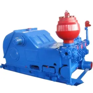
Crude Oil Production in the US (2012–2021)The market for mud pumps has also been affected due to reduced upstream activities. A mud pump is a large, high-pressure single acting triplex reciprocating pump used to circulate mud in wells with pressure. However, the operations of oil & gas exploration could be stopped to a certain extent. If the production stops, the oil wells would be sealed, which might risk the loss of the asset permanently. This would lead to huge losses and lower than zero dividends by the oil companies to the pension funds, especially in North America and Europe. On 15th May 2020, the Energy Information Administration (EIA) announced its forecast on crude oil production fall in the year 2020 and 2021 due to the falling demand for petroleum products because of the pandemic. EIA forecasts that the US crude oil production would average at 11.7 million barrels per day in 2020 and 10.9 million barrels per day in 2021. These levels would be lower than the 2019 average of 12.2 million barrels per day.

The invention relates generally to offshore drilling systems which are employed for drilling subsea wells. More particularly, the invention relates to an offshore drilling system which maintains a dual pressure gradient, one pressure gradient above the well and another pressure gradient in the well, during a drilling operation.
Deep water drilling from a floating vessel typically involves the use of a large- diameter marine riser, e.g. a 21 -inch marine riser, to connect the floating vessel"s surface equipment to a blowout preventer stack on a subsea wellhead. The floating vessel may be moored or dynamically positioned at the drill site. However, dynamically-positioned drilling vessels are predominantly used in deep water drilling. The primary functions of the marine riser are to guide the drill string and other tools from the floating vessel to the subsea wellhead and to conduct drilling fluid and earth-cuttings from a subsea well to the floating vessel. The marine riser is made up of multiple riser joints, which are special casings with coupling devices that allow them to be interconnected to form a tubular passage for receiving drilling tools and conducting drilling fluid. The lower end of the riser is normally releasably latched to the blowout preventer stack, which usually includes a flexible joint that permits the riser to angularly deflect as the floating vessel moves laterally from directly over the well. The upper end of the riser includes a telescopic joint that compensates for the heave of the floating vessel. The telescopic joint is secured to a drilling rig on the floating vessel via cables that are reeved to sheaves on riser tensioners adjacent the rig"s moon pool. The riser tensioners are arranged to maintain an upward pull on the riser. This upward pull prevents the riser from buckling under its own weight, which can be quite substantial for a riser extending over several hundred feet. The riser tensioners are
adjustable to allow adequate support for the riser as water depth and the number of riser joints needed to reach the blowout preventer stack increases. In very deep water, the weight of the riser can become so great that the riser tensioners would be rendered ineffective. To ensure that the riser tensioners work effectively, buoyant devices are attached to some of the riser joints to make the riser weigh less when submerged in water. The buoyant devices are typically steel cylinders that are filled with air or plastic foam devices.
The maximum practical water depth for current drilling practices with a large diameter marine riser is approximately 7,000 feet. As the need to add to energy reserves increases, the frontiers of energy exploration are being pushed into ever deeper waters, thus making the development of drilling techniques for ever deeper waters increasingly more important. However, several aspects of current drilling practices with a conventional marine riser inherently limit deep water drilling to water depths less than approximately 7,000 feet. The first limiting factor is the severe weight and space penalties imposed on a floating vessel as water depth increases. In deep water drilling, the drilling fluid or mud volume in the riser constitutes a majority of the total mud circulation system and increases with increasing water depth. The capacity of the 21 -inch marine riser is approximately 400 barrels for every 1,000 feet. It has been estimated that the weight attributed to the marine riser and mud volume for a rig drilling at a water depth of 6,000 feet is 1,000 to 1,500 tons. As can be appreciated, the weight and space requirements for a drilling rig that can support the large volumes of fluids required for circulation and the number of riser joints required to reach the seafloor prohibit the use of the 21 -inch riser, or any other large-diameter riser, for drilling at extreme water depths using the existing offshore drilling fleet.
The second limiting factor relates to the loads applied to the wall of a large- diameter riser in very deep water. As water depth increases, so does the natural period of the riser in the axial direction. At a water depth of about 10,000 feet, the natural period of the riser is around 5 to 6 seconds. This natural period coincides with the period of the
water waves and can result in high levels of energy being imparted on the drilling vessel and the riser, especially when the bottom end of the riser is disconnected from the blowout preventer stack. The dynamic stresses due to the interaction between the heave of the drilling vessel and the riser can result in high compression waves that may exceed the capacity of the riser.
In water depths 6,000 feet and greater, the 21 -in riser is flexible enough that angular and lateral deflections over the entire length of the riser will occur due to the water currents acting on the riser. Therefore, in order to keep the riser deflections within acceptable limits during drilling operations, tight station keeping is required. Frequently, the water currents are severe enough that station keeping is not sufficient to permit drilling operations to continue. Occasionally, water currents are so severe that the riser must be disconnected from the blowout preventer stack to avoid damage or permanent deformation. To prevent frequent disconnection of the riser, an expensive fairing may have to be deployed or additional tension applied to the riser. From an operational standpoint, a fairing is not desirable because it is heavy and difficult to install and disconnect. On the other hand, additional riser tensioners may over-stress the riser and impose even greater loads on the drilling vessel.
A third limiting factor is the difficulty of retrieving the riser in the event of a storm. Based on the large forces that the riser and the drilling vessel are already subjected to, it is reasonable to conclude that neither the riser nor the drilling vessel would be capable of sustaining the loads imposed by a hurricane. In such a condition, if the drilling vessel is a dynamically positioned type, the drilling vessel will attempt to evade the storm. Storm evasion would be impossible with 10,000 feet of riser hanging from the drilling vessel. Thus, in such a situation, the riser would have to be pulled up entirely.
In addition, before disconnecting the riser from the blowout preventer stack, operations must take place to condition the well so that the well may be safely abandoned. This is required because the well depends on the hydrostatic pressure of the mud column extending from the top end of the riser to the bottom of the well to
overcome the pore pressures of the formation. When the mud column in the riser is removed, the hydrostatic pressure gradient is significantly reduced and may not be sufficient to prevent formation fluid influx into the well. Operations to contain well pressure may include setting a plug, such as a storm packer, in the well and closing the blind ram in the blowout preventer stack.
After the storm, the drilling vessel would return to the drill site and deploy the riser to reconnect and resume drilling. In locations like Gulf of Mexico where the average annual number of hurricanes is 2.8 and the maximum warning time of an approaching hurricane is 72 hours, it would be necessary to disconnect and retrieve the riser every time there is a threat of hurricane in the vicinity of the drilling location. This, of course, would translate to huge financial losses to the well operator.
A fourth limiting factor, relates to emergency disconnects such as when a dynamically positioned drilling vessel experiences a drive off. A drive off is a condition when a floating drilling vessel loses station keeping capability, loses power, is in imminent danger of colliding with another marine vessel or object, or experiences other conditions requiring rapid evacuation from the drilling location. As in the case of the storm disconnect, well operations are required to condition the well for abandoning. However, there is usually insufficient time in a drive off to perform all of the necessary safe abandonment procedures. Typically, there is only sufficient time to hang off the drill string from the pipe/hanging rams and close the shear/blind rams in the blowout preventer before disconnecting the riser from the blowout preventer stack.
The well hydrostatic pressure gradient derived from the riser height is trapped below the closed blind rams when the riser is disconnected. Thus, the only barrier to the influx of formation fluid into the well is the closed blind rams since the column of mud below the blind rams is insufficient to prevent influx of formation fluid into the well. Prudent drilling operations require two independent barriers to prevent loss of well control. When the riser is disconnected from the blowout preventer stack, large volumes of mud will be dumped onto the seafloor. This is undesirable from both an economic and environmental standpoint.
A fifth limiting factor relates to marginal well control and the need for numerous casing points. In any drilling operation, it is important to control the influx of formation fluid from subsurface formations into the well to prevent blowout. Well control procedures typically involve maintaining the hydrostatic pressure of the drilling fluid column above the "open hole" formation pore pressure but, at the same time, not above the formation fracture pressure. In drilling the initial section of the well, the hydrostatic pressure is maintained using seawater as the drilling fluid with the drilling returns discharged onto the seafloor. This is possible because the pore pressures of the formations near the seafloor are close to the seawater hydrostatic pressure at the seafloor. While drilling the initial section of the well with seawater, formations having pore pressures greater than the seawater hydrostatic pressure may be encountered. In such situations, formation fluids may flow freely into the well. This uncontrolled flow of formation fluids into the well may be so great as to cause washouts of the drilled hole and, possibly, destroy the drilling location. To prevent formation fluid flow into the well, the initial section of the well may be drilled with weighted drilling fluids. However, the current practice of discharging fluid to the seafloor while drilling the initial section of the well does not make this option very attractive. This is because the large volumes of drilling fluids dumped onto the seafloor are not recovered. Large volumes of unrecovered weighted drilling fluids are expensive and, possibly, environmentally undesirable.
After the initial section of the well is drilled to an acceptable depth, using either seawater or weighted drilling fluid, a conductor casing string with a wellhead is run and cemented in place. This is followed by running a blowout preventer stack and marine riser to the seafloor to permit drilling fluid circulation from the drilling vessel to the well and back to the drilling vessel in the usual manner.
In geological areas characterized by rapid sediment deposition and young sediments, fracture pressure is a critical factor in well control. This is because fracture pressure at any point in the well is related to the density of the sediments resting above that point combined with the hydrostatic pressure of the column of seawater above.
These sediments are significantly influenced by the overlying body of water and the circulating mud column need only be slightly denser than seawater to fracture the formation. Fortunately, because of the higher bulk density of the rock, the fracture pressure rapidly increases with the depth of penetration below the seafloor and will present a less serious problem after the first few thousand feet are drilled. However, abnormally high pore pressures which are routinely encountered up to 2,000 feet below the seafloor continue to present a problem both when drilling the initial section of the well with seawater and when drilling beyond the initial section of the well with seawater or weighted drilling fluid. The challenge then becomes balancing the internal pressures of the formation with the hydrostatic pressure of the mud column while continuing drilling of the well. The current practice is to progressively run and cement casings, the next inside the previous, into the hole to protect the "open hole" sections possessing insufficient fracture pressure while allowing weighted drilling fluids to be used to overcome formation pore pressures. It is important that the well be completed with the largest practical casing through the production zone to allow production rates that will justify the high-cost of deep-water developments. Production rates exceeding 10,000 barrels per day are common for deep-water developments, and too small a production casing would limit the productivity of the well, making it uneconomical to complete. The number of casings run into the hole is significantly affected by water depth.
The multiple casings needed to protect the "open hole" while providing the largest practical casing through the production zone requires that the surface hole at the seafloor be larger. A larger surface hole in turn requires a larger subsea wellhead and blowout preventer stack and a larger blowout preventer stack requires a larger marine riser. With a larger riser, more mud is required to fill the riser and a larger drilling vessel is required to carry the mud and support the riser. This cycle repeats itself as water depth increases.
It has been identified that the key to breaking this cycle lies in reducing the hydrostatic pressure of the mud in the riser to that of a column of seawater and providing mud with sufficient weight in the well to maintain well control. Various concepts have
been presented in the past for achieving this feat; however, none of these concepts known in the prior art have gained commercial acceptance for drilling in ever deeper waters. These concepts can be generally grouped into two categories: the mud lift drilling with a marine riser concept and the riserless drilling concept. The mud lift drilling with a marine riser concept contemplates a dual-density mud gradient system which includes reducing the density of the mud returns in the riser so that the return mud pressure at the seafloor more closely matches that of seawater. The mud in the well is weighted to maintain well control. For example, U.S. Patent No. 3,603,409 to Watkins et al. and U.S. Patent No. 4,099,583 to Maus et al. disclose methods of injecting gas into the mud column in the marine riser to lighten the weight of the mud.
The riserless drilling concept contemplates eliminating the large-diameter marine riser as a return annulus and replacing it with one or more small-diameter mud return lines. For example, U.S. Patent No. 4,813,495 to Leach removes the marine riser as a return annulus and uses a centrifugal pump to lift mud returns from the seafloor to the surface through a mud return line. A rotating head isolates the mud in the well annulus from the open seawater as the drill string is run in and out of the well.
Drilling rates are significantly affected by the magnitude of the difference between formation pore pressure and mud column pressure. This difference, commonly called "overbalance", is adjusted by changing the density of the mud column. Overbalance is estimated as the additional pressure required to prevent the well from kicking, either during drilling or when pulling a drill string out of the well. This overbalance estimate usually takes into account factors like inaccuracies in predicting formation pore pressures and pressure reductions in the well as a drill string is pulled from the well. Typically, a minimum of 300 to 700 psi overbalance is maintained during drilling operations. Sometimes the overbalance is large enough to damage the formation.
The effect of overbalance on drilling rates varies widely with the type of drill bit, formation type, magnitude of overbalance, and many other factors. For example, in a typical drill bit and formation combination with a drilling rate of 30 feet per hour and an overbalance of 500 psi, it is common for the drilling rate to double to 60 feet per hour if
the overbalance is reduced to zero. An even greater increase in drilling rate can be achieved if the mud column pressure is decreased to an underbalanced condition, i.e. mud column pressure is less than formation pressure. Thus, to improve drilling rates, it may be desirable to drill a well in an underbalanced mode or with a minimum of overbalance. In conventional drilling operations, it is impractical to reduce the mud density to allow faster drilling rates and then increase the mud density to permit tripping the drill string. This is because the circulation time for the complete mud system lasts for several hours, thus making it expensive to repeatedly decrease and increase mud density. Furthermore, such a practice would endanger the operation because a miscalculation could result in a kick.
In general, in one aspect, a positive-displacement pump comprises multiple pumping elements, each pumping element comprising a pressure vessel with a first and a second chamber and a separating member disposed between the first and second chambers. The first chambers and the second chambers are hydraulically connected to receive and discharge fluid, wherein the separating members move within the pressure vessels in response to pressure differential between the first and second chambers. A valve assembly having suction and discharge valves communicates with the first chambers. The suction and discharge valves are operable to permit fluid to alternately flow into and out of the first chambers. A hydraulic drive alternately supplies hydraulic fluid to and withdraws hydraulic fluid from the second chambers such that the fluid discharged from the first chambers is substantially free of pulsation.
FIG. 2A is a detailed view of the well control assembly shown in FIG. 1. FIG. 2B is a detailed view of the mud lift module shown in FIG. 1. FIG. 2C is a detailed view of the pressure-balanced mud tank shown in FIG. 1.
FIGS. 3 A and 3B are cross sections of non-rotating subsea diverters. FIGS. 4A-4F are cross sections of rotating subsea diverters. FIG. 5 is a cross section of a wiper.
FIG. 8 is an elevation view of a subsea mud pump. FIG. 9A is a cross section of a diaphragm pumping element. FIG. 9B is a cross section of a piston pumping element.
FIG. 1 OB is a graph illustrating output characteristics of the open-circuit hydraulic drive shown in FIG. 10A. FIG. IOC illustrates the performance of the open-circuit hydraulic drive shown in
FIG. 16 is a diagram of a mud circulation system for the offshore drilling system shown in FIG. 1. FIG. 17 is a graph of depth versus pressure for a well drilled in a water depth of
FIG. 20A is a graph of depth versus pressure for a well drilled in a water depth of 5,000 feet for a dual-density mud gradient system which has a mudline pressure less than seawater pressure.
FIG. 21 illustrates the offshore drilling system of FIG. 1 with a mud lift module mounted on the seafloor. FIGS. 22A and 22B are elevation views of retrievable subsea components of the offshore drilling system shown in FIG. 21.
FIG. 26 is a top view of another embodiment of the return line riser shown in FIG. 23. FIG. 27 illustrates the offshore drilling system of FIG. 1 without a marine riser and with a mud lift module mounted on the seafloor.
FIG. 31 is a graph of depth versus pressure for the initial section of well drilled in a water depth of 5,000 feet using the subsea flow assembly shown in FIG. 30.
DETAILED DESCRIPTION FIG. 1 illustrates an offshore drilling system 10 where a drilling vessel 12 floats on a body of water 14 which overlays a pre-selected formation. The drilling vessel 12 is dynamically positioned above the subsea formation by thrusters 16 which are activated by on-board computers (not shown). An array of subsea beacons (not shown) on the seafloor 17 sends signals which are indicative of the location of the drilling vessel 12 to hydrophones (not shown) on the hull of the drilling vessel 12. The signals received by the hydrophones are transmitted to on-board computers. These on-board computers process the data from the hydrophones along with data from a wind sensor and other auxiliary position-sensing devices and activate the thrusters 16 as needed to maintain the drilling vessel 12 on station. The drilling vessel 12 may. also be maintained on station by using several anchors that are deployed from the drilling vessel to the seafloor. Anchors, however, are generally practical if the water is not too deep.
A drilling rig 20 is positioned in the middle of the drilling vessel 12, above a moon pool 22. The moon pool 22 is a walled opening that extends through the drilling vessel 12 and through which drilling tools are lowered from the drilling vessel 12 to the seafloor 17. At the seafloor 17, a conductor pipe 32 extends into a well 30. A conductor housing 33, which is attached to the upper end of the conductor pipe 32, supports the conductor pipe 32 before the conductor pipe 32 is cemented in the well 30. A guide structure 34 is installed around the conductor housing 33 before the conductor housing 33 is run to the seafloor 17. A wellhead 35 is attached to the upper end of a surface pipe 36 that extends through the conductor pipe 32 into the well 30. The wellhead 35 is of conventional design and provides a method for hanging additional casing strings in the well 30. The wellhead 35 also forms a structural base for a wellhead stack 37.
The wellhead stack 37 includes a well control assembly 38, a mud lift module 40, and a pressure-balanced mud tank 42. A marine riser 52 between the drilling rig 20 and the wellhead stack 37 is positioned to guide drilling tools, casing strings, and other equipment from the drilling vessel 12 to the wellhead stack 37. The lower end of the marine riser 52 is releasably latched to the pressure-balanced mud tank 42, and the upper end of the marine riser 52 is secured to the drilling rig 20. Riser tensioners 54 are provided to maintain an upward pull on the marine riser 52. Mud return lines 56 and 58, which may be attached to the outside of the marine riser 52, connect flow outlets (not shown) in the mud lift module 40 to flow ports in the moon pool 22. The flow ports in the moon pool 22 serve as an interface between the mud return lines 56 and 58 and a mud return system (not shown) on the drilling vessel 12. The mud return lines 56 and 58 are also connected to flow outlets (not shown) in the well control assembly 38, thus allowing them to be used as choke/kill lines. Alternatively, the mud return lines 56 and 58 may be existing choke/kill lines on the riser.
A drill string 60 extends from a derrick 62 on the drilling rig 20 into the well 30 through the marine riser 52 and the wellhead stack 37. Attached to the end of the drill string 60 is a bottom hole assembly 63, which includes a drill bit 64 and one or more drill collars 65. The bottom hole assembly 63 may also include stabilizers, mud motor, and
other selected components required for drilling a planned trajectory, as is well known in the art. During normal drilling operations, the mud pumped down the bore of the drill string 60 by a surface pump (not shown) is forced out of the nozzles of the drill bit 64 into the bottom of the well 30. The mud at the bottom of the well 30 rises up the well annulus 66 to the mud lift module 40, where it is diverted to the suction ends of subsea mud pumps (not shown). The subsea mud pumps boost the pressure of the returning mud flow and discharge the mud into the mud return lines 56 and/or 58. The mud return lines 56 and/or 58 then conduct the discharged mud to the mud return system (not shown) on the drilling vessel 12. The drilling system 10 is illustrated with two mud return lines 56 and 58, but it should be clear that a single mud return line or more than two mud return lines may also be used. Clearly the diameter and number of the return lines will affect the pumping requirements for the subsea mud pumps in the mud lift module 40. The subsea mud pumps must provide enough pressure to the returning mud flow to overcome the frictional pressure losses and the hydrostatic head of the mud column in the return lines. The wellhead stack 37 includes subsea diverters (not shown) which seal around the drill string 60 and form a separating barrier between the riser 52 and the well annulus 66. The riser 52 is filled with seawater so that the hydrostatic pressure of the fluid column at the seafloor or mudline or separating barrier formed by the subsea diverters is that of seawater. Filling the riser with seawater, as opposed to mud, reduces the riser tension requirements. The riser may also be filled with other fluids which have a lower specific gravity than the mud in the well annulus.
Well Control Assembly FIG. 2A shows the components of the well control assembly 38 which was previously illustrated in FIG. 1. As shown, the well control assembly 38 includes a lower marine riser package (LMRP) 44 and a subsea blowout preventer (BOP) stack 46. The BOP stack 46 includes a pair of dual ram preventers 70 and 72. However, other combinations, such as, a triple ram preventer combined with a single ram preventer may
be used. Additional preventers may also be required depending on the preferences of the drilling operator. The ram preventers are equipped with pipe rams for sealing around a pipe and shear/blind rams for shearing the pipe and sealing the well. The ram preventers 70 and 72 have flow ports 76 and 78, respectively, that may be connected to choke/kill lines (not shown). A wellhead connector 88 is secured to the lower end of the ram preventer 70. The wellhead connector 88 is adapted to mate with the upper end of the wellhead 35 (shown in FIG. 1).
The LMRP 44 includes annular preventers 90 and 92 and a flexible joint 94. However, the LMRP 44 may take on other configurations, e.g., a single annular preventer and a flexible joint. The annular preventers 90 and 92 have flow ports 98 and 100 that may be connected to choke/kill lines (not shown). The lower end of the annular preventer 90 is connected to the upper end of the ram preventers 72 by a LMRP connector 93. The flexible joint 94 is mounted on the upper end of the annular preventer 92. A riser connector 114 is attached to the upper end of the flexible joint 94. The riser connector 114 includes flow ports 113 which may be hydraulically connected to the flow ports 76, 78, 98, and 100. The LMRP 44 includes control modules (not shown) for operating the ram preventers 70 and 72, the annular preventers 90 and 92, various connectors and valves in the wellhead stack 37, and other controls as needed. Hydraulic fluid is supplied to the control modules from the surface through hydraulic lines (not shown) that may be attached to the outside of the riser 52 (shown in FIG. 1).
Mud lift module FIG. 2B shows the components of the mud lift module 40 which was previously illustrated in FIG. 1. As shown, the mud lift module 40 includes subsea mud pumps 102, a flow tube 104, a non-rotating subsea diverter 106, and a rotating subsea diverter 108. The lower end of the flow tube 104 includes a riser connector 110 which is adapted to mate with the riser connector 114 (shown in FIG. 2 A) at the upper end of the flexible joint 94. When the riser connector 110 mates with the riser connector 114, the flow ports 111 in the riser connector 110 are in communication with the flow ports 113 (shown in
FIG. 2 A) in the riser connector 114. A riser connector 112 is mounted at the upper end of the subsea diverter 108. The flow ports 111 in the riser connector 110 are connected to flow ports 116 in the riser connector 112 by pipes 118 and 120, and the pipes 118 and 120 are in turn hydraulically connected to the discharge ends of the subsea mud pumps 102. The suction ends of the subsea mud pumps 102 are hydraulically connected to flow outlets 125 in the flow tube 104.
The subsea diverters 106 and 108 are arranged to divert mud from the well annulus 66 (shown in FIG. 1) to the suction ends of the subsea mud pumps 102. The diverters 106 and 108 are also adapted to slidingly receive and seal around a drill string, e.g., drill string 60. When the diverters seal around the drill string 60, the fluid in the flow tube 104 or below the diverters is isolated from the fluid in the riser 52 (shown in FIG. 1) or above the diverters. The diverters 106 and 108 may be used alternately or together to sealingly engage a drill string and, thereby, isolate the fluid in the annulus of the riser 52 from the fluid in the well annulus 66. It should be clear that either the diverter 106 or 108 may be used alone as the separating medium between the fluid in the riser 52 and the fluid in the well annulus 66. A rotating blowout preventer (not shown), which could be included in the well control assembly 38 (shown in FIG. 2 A), may also be used in place of the diverters. The diverter 108 may also be mounted on the annular preventer 92 (shown in FIG. 2 A), and mud flow into the suction ends of the subsea pumps 102 may be taken from a point below the diverter.
Non-rotating subsea diverter FIG. 3 A shows a vertical cross section of the non-rotating subsea diverter 106 which was previously illustrated in FIG. 2B. As shown, the non-rotating subsea diverter 106 includes a head 126 that is fastened to a body 128 by bolts 130. However, other means, such as a screwed or radial latched connection, may be used in place of bolts 130. The body 128 has a flange 131 that may be bolted to the upper end of the flow tube 104, as shown in FIG. 2B. The head 126 and body 128 are provided with bores 132 and 134, respectively. The bores 132 and 134 form a passageway 136 for receiving a drill string,
e.g., drill string 60. The body 128 has a closing cavity 138 and an opening cavity 139. A piston 140 is arranged to move inside the cavities 138 and 139 in response to pressure of the hydraulic fluid fed into these cavities. At the upper end of the body 128 is a sleeve 142 and cover 143 which guide the piston 140 as it moves inside the cavities 138 and 139.
The cavity 138 is enveloped by the body 128, the piston 140, and the sleeve 142. The cavity 139 is enveloped by the body 128, the piston 140, and cover 143. As the piston 140 moves inside the cavities 138 and 139, seal rings 144 contain hydraulic fluid in the cavities. The sleeve 142 is provided with holes 148 for venting fluid out of a cavity 145 below the piston 140. A resilient, elastomeric, toroid-shaped, sealing element 150 is located between the upper end of the piston 140 and a tapered portion 152 of the internal wall of the head 126. The sealing element 150 may be actuated to seal around a drill string, e.g., drill string 60, in the passageway 136.
The piston 140 moves downwardly to open the passageway 136 when hydraulic fluid is supplied to the opening cavity 139. As illustrated in the left half of the drawing, when the piston 140 sits on the body 128, the sealing element 150 does not extrude into the passageway 136 and the diverter 106 is fully open. When the diverter 106 is fully open, the passageway 136 is large enough to receive a bottom hole assembly and other drilling tools. When hydraulic fluid is fed into the cavity 138, the piston 140 moves upwardly to close the diverter 106. As illustrated in the right half of the drawing, when the piston 140 moves upwardly, the sealing element 150 is extruded into the passageway 136. If there is a drill string in the passageway 136, the extruded sealing element 150 would contact the drill string and seal the annulus between the passageway 136 and the drill string. FIG. 3B shows a vertical cross section of another non-rotating subsea diverter, i.e., subsea diverter 270, that may be used in place of the non-rotating subsea diverter 106. The subsea diverter 270 includes a housing body 272 with flanges 274 and 276 which are provided for connection with other components of the wellhead stack 37, e.g., the flow tube 104 and the subsea diverter 108 (shown in FIG. 2B). The housing body
272 is provided with a bore 278 and pockets 280. The pockets 280 are distributed along a circumference of the housing body 272. Inside each pocket 280 is a retractable landing shoulder 282 and a lock 284. Hydraulic actuators 285 are provided to actuate the locks 284 to engage a retrievable stripper element 286 which is disposed within the bore 278 of the housing body 272.
The stripper element 286 includes a stripper rubber 288 that is bonded to a metal body 290. The locks 284 slide into recesses 291 in the metal body 290 to lock the metal body 290 in place inside the housing body 272. A seal 292 on the metal body 290 forms a seal between the housing body 272 and the metal body 290. The stripper rubber 288 sealingly engages a drill string that is received inside the bore 278 while permitting the drill string to rotate and move axially inside the bore 278. The stripper rubber 288 does not rotate with the drill string so the rubber 288 is subjected to friction forces associated with both the rotational and vertical motions of the drill string. The stripper element 286 may be carried into and out of the housing body 272 on a handling tool which may be positioned above the bottom hole assembly of the drill string.
Rotating subsea diverter FIG. 4A shows a vertical cross section of the rotating subsea diverter 108 which was previously illustrated in FIG. 2B. As shown, the rotating subsea diverter 108 includes a housing body 162 with flanges 164 and 166. The flange 164 is arranged to mate with the upper end of the diverter 106 (shown in FIG. 3 A). The housing body 162 is provided with a bore 168 and pockets 170. The pockets 170 are distributed along a circumference of the housing body 162. Inside each pocket 170 is a retractable landing shoulder 174 and a lock 176. Hydraulic actuators 177 are provided to operate the locks 176. Although the lock 176 is shown as being hydraulically actuated, it should be clear that the lock 176 may be actuated by other means, e.g., the lock 176 may be radially loaded with springs. The lock 176 may also incorporate a mechanism that permits intervention by a remote operated vehicle (ROV) such as a "T" handle in series with the actuator for gripping by the ROV manipulator.
A retrievable spindle 178 is disposed in the bore 168 of the housing body 162. The spindle 178 has an upper portion 180 and a lower portion 182. The upper portion 180 has recesses 181 into which the locks 176 may slide to lock the upper portion 180 in place inside the housing body 162. A seal 183 on the upper portion 180 seals between the housing body 162 and the upper portion 180. A bearing assembly 184 is attached to the upper portion 180. The bearing assembly 184 has bearings which support the lower portion 182 of the spindle 178 for rotation inside the housing body 162. A stripper rubber 185 is bonded to the lower portion 182 of the spindle 178. The stripper rubber 185 rotates with and sealingly engages a drill string (not shown) that is received in the bore 168 while permitting the drill string to move vertically.
In operation, the spindle 178 is carried into the housing body 162 on a handling tool that is mounted on the drill string. When the spindle 178 lands on the shoulder 174, the drill string is rotated until the locks 176 are aligned with the recesses 181 in the upper portion 180 of the spindle 178. Then the hydraulic actuators 177 are operated to push the locks 176 into the recesses 181. The stripper rubber 185 seals against the drill string while allowing the drill string to be lowered into the well. During drilling, friction between the rotating drill string and the stripper rubber 185 provides sufficient force to rotate the lower portion 182 of the spindle 178. While the lower portion 182 is rotated, the stripper rubber 185 is only subjected to the friction forces associated with the vertical motion of the drill string. This has the effect of prolonging the wear life of the stripper rubber 185


 8613371530291