
crankshaft mud pump free sample

A wide variety of mud pump crankshaft options are available to you, such as 1 year, not available and 2 years.You can also choose from new, mud pump crankshaft,as well as from energy & mining, construction works , and machinery repair shops mud pump crankshaft, and whether mud pump crankshaft is 1.5 years, 6 months, or unavailable.

This application is a continuation of pending U.S. patent Ser. No. 12/220,876 entitled “A Reinforced Smart Mud Pump” which take priority to provisional application for patent filed Jul. 30, 2007 bearing Ser. No. 60/962,637 and is incorporated by reference herein as if fully set forth.
This invention relates generally to the field of mud pumps and more specifically to a reinforced smart mud pump. Mud pumps that use piston displacement, produce imposed forces that cause wear and tear on various pump components, including pump cross head piping, cylinders, inlet and discharge valves, seal components including piston or plunger seals, the pump cylinder block or so-called fluid end, and other components. There has been a need to provide increased longevity and performance for such pumps and to determine if deteriorations in pump performance are occurring, to analyze the source of decreased performance and to further real time control and data to monitor and in some cases change the operating characteristics before damage occurs to the pump. The use of greatly strengthened components in combination with a computer controlled system integrated with a real time monitored and controlled reset relief valve may be integrated into an oilfield application to prevent catastrophic pump failure and extend pump life.
Pump operating characteristics often have a deleterious effect on pump performance. For example, delayed valve closing and sealing can result in loss of volumetric efficiency. Factors affecting pump valve performance include fluid properties, valve spring design and fatigue life, valve design and the design of the cylinder or fluid end housing. Delayed valve response also causes a higher pump chamber pressure than normal which in turn may cause overloads on pump mechanical components, including the pump crankshaft or eccentric and its bearings, speed reduction gearing, the pump drive shaft and the pump prime mover. Moreover, increased fluid acceleration induced pressure “spikes” in the pump suction and discharge flowstreams can be deleterious. Fluid properties are also subject to analysis to determine compressibility, the existence of entrained gases in the pump fluid stream, susceptibility to cavitation and the affect of pump cylinder or fluid end design on fluid properties and vice versa.
Still further, piston or plunger seal or packing leaking can result in increased delay of pump discharge valve opening with increased hydraulic flow and acceleration induced hydraulic forces imposed on the pump and its discharge piping. Moreover, proper sizing and setup of pulsation control equipment is important to the efficiency and long life of a pump system. Pulsation control equipment location and type can also affect pump performance as well as the piping system connected to the pump
In prior art, the control of a mud pump has been disclosed focused on piston position for acquiring information about the pump and its performance characteristics. For example, U.S. Pat. No. 6,882,960 to Miller, shows a system for monitoring and analyzing performance parameters of reciprocating piston, or power pumps and associated piping systems. This patent fails to disclose the innovative aspects of the present invention.
Nothing in the prior art shows a computer integrated mud pump with significant strengthening features that increase the life cycle of a pump in the manner of the present invention with real time control of significant operating functions and feedback from various sensors and reset relief valves.
Another advantage of the invention is to provide a mud pump that utilizes transducers in line with the ambient pressure in conjunction with a computer controlled pressure relief valve to record and monitor pump characteristics and control the pump to prevent catastrophic failure.
Another advantage of the invention is to provide a mud pump that transmits data to a computer for later analysis of important operating characteristics.
A further advantage of the invention is to provide a mud pump that can be controlled during its operation to prevent certain damaging events to the pump or underlying pressurized system.
In accordance with a preferred embodiment of the invention, there is shown a pump system for movement of fluids having a reciprocating piston power pump having at least three reciprocating pistons operable to displace fluid from a housing having a pumping chamber, an integrally forged crankshaft operably connected to the pistons, at least one sensor operable to sense ambient conditions on the pump, and a computer control for processing data from the sensor to regulate the operation of the pump in response to the data.
In accordance with a preferred embodiment of the invention, there is shown a pump system for movement of fluids having a reciprocating piston power pump having at least three reciprocating pistons operable to displace fluid from a housing having a pumping chamber, an integrally forged crankshaft operably connected to the pistons, polyflorocarbon infused treatement applied to at least one crosshead and one crosshead slide in the system, and at least one sensor operable to sense ambient conditions on the pump.
In accordance with a preferred embodiment of the invention, there is shown a pump system for movement of fluids having a reciprocating piston power pump having at least three reciprocating pistons operable to displace fluid from a housing having a pumping chamber, an integrally forged crankshaft operably connected to the pistons, at least one sensor operable to sense ambient conditions on the pump, a computer control for processing data from the sensor to regulate the operation of the pump in response to the data; and pressure sensors for monitoring fluid pressure operably connected to the computer control. In addition, upper and lower limits to temperature, vibration and pressure can be set. Further, in a preferred embodiment, all lubrication and water pumps must be on before the control system will permit unit to be operated.
In a preferred embodiment of the present invention, there is shown a reciprocating plunger or piston power pump. The pump includes additional features not found in conventional reciprocal pumps as heretofore described. The basic operation of the pump is similar to a triplex plunger pump configured to reciprocate three spaced apart plungers or pistons, which are connected by suitable connecting rod and crosshead mechanisms, to a rotatable crankshaft or eccentric. FIG. 1 shows a side view of the pump and auxiliary equipment according to a preferred embodiment of the invention. Pump housing 100 covers the internal pump components and allows for a variety of conventional means to move the rotatable crankshaft 114 such as an electric motor 102 and belt drive 104. Within pump housing 100 may be disposed a pressurized lubrication spraying system that continuously feeds lubricant such as oil around the crankshaft and associated internal pump components.
A suction module 104 of conventional design houses each plunger which operates each section of the triplex plunger pump. A pressure relief valve mount 110 allows for attachment of a reset relief valve (show in FIG. 5) to at least one suction module 106 in a system for pumping drilling mud composed of water, clay and chemical additives, down through the inside of a drill pipe of an oil well drilling operation. The drilling mud is pumped at very high pressure so the mud is forced out through a bit at the lower end of the drill pipe and returned to the surface, carrying rock cuttings from the well. In this illustrative example the drilling mud from the pump system is fed into the attached vessel 112 sometimes known as a dumping ball. In a preferred embodiment all components are installed on a full unitized skid 120 providing room for motors, starters, sheaves, belts and any associated test equipment and a solid platform for installation of bracing 122 for component parts. Vessel 112 smoothes out the pulsation caused by the pumping action of the system to deliver pumped fluid out of port 115 in a more controlled manner.
With the use of computer modeling, high technology engineering, metallurgical and mechanical enhancements, the smart pump is revolutionary in design. The pump is manufactured using advanced materials and techniques including an integrally forged and balanced crank. This provides significant strength advantages and increases the life cycle of the pump. Unlike prior art pump systems, the crank is not a porous unbalanced crank casting, nor is it a fabricated with separate plates and bars and later welded together. As shown in FIG. 2 the crank 200 is fabricated from an integrally forged single ingot by the open hammer forging process resulting in a single piece with no welding or pinning of multiple pieces. A connecting rod 202 for each plunger is attached to the crank 200 such that the crank freely rotates and creates a reciprocating action in each connecting rod 202 attached to the crank 200. A crosshead 204 and crosshead slide 206 attach to each connector rod to help retain engine oil in the crankcase. A plunger connection 210 at each connector rod 202 end provides a means of attachment for a variety of rod and plunger components.
All of the ground crossheads 204 and honed crosshead slides 206 are treated with a polyflorocarbon coating for more lubricity and wear performance characteristics resulting in 15% less energy cost. This process has been used in the racing industry with much higher performance results. The poly-fluorocarbon coating is applied to each crosshead and slide and helps retain engine oil on the component surfaces during intense heat and extreme pressure. The oil is essentially absorbed into each crosshead 204 and slide 206 in such a way as to increase their lubricity. The crosshead 204 center line alignment is laser monitored for even wear. In a preferred embodiment of the invention the pump uses suction modules, discharge modules and discharge manifold and a double helical gear set. All gear sets are prepared with mesh test providing contact tapes accompanied by digitals to AGMS 11+ standards. All gear sets are further preferably chemically treated to 0.4 RMS or better to exponentially increase bearing life.
In the present invention, the crankshaft is a integrally forged piece to increase its operating strength significantly, and is an integral part of the crank 200. The terms crank 200 and crankshaft are used interchangably although in conventional pumps and engines the crank 200 and crankshaft may comprise separate components. Turning again to FIG. 1 we see the crankshaft includes a rotatable input shaft portion adapted to be operably connected to a suitable prime mover, such as an internal combustion engine or electric motor 102, as an exemplary installation. The crankshaft is mounted in a suitable, so-called power end housing 114 which is connected to a fluid end structure configured to have a plurality of pumping chambers, in this example, three separate pumping chambers exposed to their respective plungers or pistons. Plungers refer to the rod, rod joints and piston end portions of the plunger unless otherwise specified.
FIG. 3 shows a partial cutaway side view of the pump according to a preferred embodiment of the invention. The fluid end comprises a housing having the series of plural cavities or chambers for receiving fluid from an inlet manifold by way of conventional poppet type inlet or suction valves contained each suction module 300. The piston or plunger 304 projects at one end into the chamber and is connected to a suitable crosshead mechanism 306, including a crosshead extension. The crosshead extension is operably connected to the crankshaft using connecting rods 308 as described above. Each plunger 306 projects through a conventional packing 310 or plunger 306 seal. Each chamber for each plunger 306 is operably connected to a discharge piping manifold by way of a suitable discharge valve. Valves may be of a variety of conventional designs and are typically spring biased to their closed positions. Valves may also include or are associated with removable valve seat members. Each valve may also have a seal member formed thereon engageable with the associated valve seat to provide fluid sealing when the valves are in their respective closed and seat engaging positions. A unique feature of a preferred embodiment of the the smart pump is a positive air pressure plunger seal 312 to prevent leakage and prevent wear on the plunger. FIG. 3A shows a cross sectional view of the positive air pressure plunger seal about a synchronized plunger according to a preferred embodiment of the invention. As the plunger 350 moves reciprocally, pressurized air is introduced into through seal 352 through a plurality of pressurized air ports 354 preventing fluid leakage from the plunger 350 end which engages and moves drilling mud through the aforementioned valves. The pressurized air flow 356 isolates any material from scoring and etching the plunger 350 and reduces friction between the seal wall and the plunger 350.
In a preferred embodiment the pump may be fitted with a P-QUIP ® fluid end systems including P-QUIP ® kwik clamp liner retentions system, P-QUIP ® kwik rod system and cover system. The P-QUIP ® kwik-clamp valve and strainer cover retention system has a very fast and safe access with much reduced down time and LTAs (Lost Time Accidents) due to mishaps. Hammers or cheater bars are not required and the system includes an automatic clamping means which results in no more under or over tightening—caps will not loosen off in use. This all results in easy installation and easy operation with conventional air or hand operated hydraulic pump. Like the Liner Retention System, the valve and strainer covers are sealed firmly in the fluid end by means of a spring mechanism. Similarly, the outer cover is removed when the clamping force is released by means of the hydraulic pump. This system heightens safety as it is no longer necessary to tighten OEM type threaded cap retainers by hammer.
The P-QUIP ® kwik rod system allows for fast and safe piston changes and is constructed of 17.4 PH martensitic high-resistance stainless steel, eliminating corrosion. Three piece rod system is held together using pins, which eliminates prior systems and clamp type systems. The P-QUIP ® kwik cover system allows for fast and save valve access changes with no hammers or cheater bars. The cover offers a positive retention force against the plug eliminating the need for retightening. The P-Quip ® kwik rod pump rod system permits fast and safe piston changes resulting in reduced down time. There is no need for heavy clamps or connecting threads and studs. The clamping force is automatically controlled resulting in no broken rod ends. Due to its construction, its self alignment facility gives improved piston and liner life. There are no corrosion problems as all parts are stainless steel, including hard-surfaced stainless steel power end rods. It has an integral liner flushing systems.
On conventional mud-pump rod systems, the rod is held together by means of taper clamps and screw threads which are slow and awkward to assemble correctly and readily wear out. Due to their design, the clamps obscure vision of the rod joints, preventing a check being made that the rod is correctly aligned. Uneven loads are imposed on the flanged rod ends, resulting in premature failure.
The P-QUIP ® Kwik-Rod system avoids these problems as the rod components are held together by powerful spring-loaded ends on a release link in the center of the rod assembly. The ends of the release link are attached to the pony rod and piston rod by means of high tensile stainless steel pins held in shear. The shear force is very quickly and easily released by a few strokes of a small hydraulic pump.
Dismantling and re-assembly of the complete rod system takes under one minute. Furthermore, there are no flanged joints on the rods to chip, wear or break. Hence, rod life is enhanced and, because rod alignment is readily achieved, significantly improved swab and liner life is generally obtained. FIG. 4 shows a partial cutaway overhead of the pump housing according to a preferred embodiment of the invention. Plunger rods 400 are synchronized based on the crank speed and can be checked for alignment as described herein. In a preferred embodiment, a viewing port 402 or access cover allows access to plunger rods 400 for alignment and maintenance.
Further enhancement to the pump is achieved by use of ductile iron for the crossheads, the crosshead slides and the connecting rods. The connecting rods are solid ductile iron which reduces their elongation during setoff to zero. The typical rod experiences stretching or elongation during set-off when the relief valve is activated. The benefit of ductile iron in increased strength and higher tensile strength. All the major components, the crank, the crossheads, the slides and the rods by use of mettalurgical engineering are designed to bring the pump tensile strength up to 200,000 p.s.i.
The pump is network and web based with a data acquisition system to monitor pump performance and constantly evaluate pump valve dynamics. Pressure transducers are located in pump chambers used to determine valve sealing delays, fluid compression delays, chamber overshoot pressure, crosshead loading shock forces and chamber volumetric efficiency. Pressure transducers are also located in suction piping and manifolds and discharge piping and manifold. Temperature is similarly monitored for fluid temperature for mud properties and power end lubrication. Further, there is real time power input data to calculate system mechanical efficiency.
Those skilled in the art will recognize that the present invention may be utilized with a wide variety of single and multi-cylinder reciprocating piston power pumps as well as possibly other types of positive displacement pumps. However, the system and method of the invention are particularly useful for analysis of reciprocating piston or plunger type pumps. Moreover, the number of cylinders of such pumps may vary substantially between a single cylinder and essentially any number of cylinders or separate pumping chambers and the illustration of a so called triplex or three cylinder pump is exemplary.
The performance analysis system of the invention is characterized, in part, by a digital signal processor which is operably connected to a plurality of sensors via suitable conductor means well known in the art. The processor may be of a type commercially available as previously described and may wireless remote and other control options associated therewith. The processor is operable to receive signals from a power input sensor which may comprise a torque meter or other type of power input sensor. Power end crankcase oil temperature may be measured by a sensor. Crankshaft and piston position may be measured by a non-intrusive sensor including a beam interrupter mountable on a pump crosshead extension for interrupting a light beam provided by a suitable light source or optical switch.
A vibration sensor may be mounted on the power end or on the discharge piping or manifold for sensing vibrations generated by the pump. Suitable pressure sensors are adapted to sense pressures at numerous locations, including the inlet piping and manifolds. Other pressure sensors may sense pressures in the pumping chambers of the respective plungers or pistons. Other pressure sensors sense pressures upstream and downstream of a discharge pulsation dampener. Still further, a fluid temperature sensor may be mounted on discharge manifold or piping to sense the discharge temperature of the working fluid. Fluid temperature may also be sensed at the inlet or suction manifold.
Pump performance analysis using the system may require all or part of the sensors described above, as those skilled in the art will understand and appreciate from the description which follows. The processor may be connected to a terminal or further processor, including a display unit or monitor mounted in a housing connected to the pump system and main housing. Still further, the processor may be connected to a signal transmitting network, such as the Internet, or a local network.
FIG. 4A shows a schematic drawing of a representative computer controlled monitoring system. A computer 450 receives input from from sensors 452 and modules 454 in the pump system and uses software algorithyms to analyze pump performance, record and display operational data on a visual screen display 456. The computer controlled monitoring system may be adapted to provide a wide array of graphic displays and data associated with the performance of a power pump on a real time or replay basis. A substantial amount of information is available including pump identification (Pump ID) crankshaft speed, fluid flow rate, time lapse since the beginning of the display, starting date and starting time and scan rate. The display 456 displays discharge piping operating pressure, peak-to-peak pressures, fluid flow rate induced peak-to-peak pressure, fluid flow induced peak-to-peak pressure as a percentage of average operating pressure, pump volumetric efficiency and pump mechanical efficiency. The display 456 also indicates discharge valve seal delay in degrees of rotation of the crankshaft from a so called piston zero or top dead center (maximum displacement) starting point with respect to the respective cylinder chambers of the pump, as well as piston seal pressure variation during fluid compression and suction valve seal delay in degrees of rotation of the crankshaft or eccentric from the top dead center position of the respective cylinder chambers. Still further, the pump type may be displayed as well as suction piping pressures, as indicated. The parameters displayed are determined by the system of the invention which utilizes the various sensors.
Various pressure sensors 452 sense pressure in the respective pump chambers associated with each of the pistons and pressure signals are transmitted to the processor. These pressure signals may indicate when valves are opening and closing. For example, if the pressure sensed in a pump chamber does not rise essentially instantly, after the piston for that chamber passes bottom dead center by 0 degrees to 10 degrees of crankshaft rotation, then it is indicated that the inlet or suction valve is delayed in closing or is leaking. In situations like this, the display may show that a discharge valve is not closed for 16.7 degrees of rotation after piston top dead center position. Accordingly, pressure changes, or the lack thereof, are sensed by cylinder chamber pressure sensors.
Software embedded in the computer 450 processor is operable to correlate the angle of rotation of the crankshaft with respect to pressure sensed in the respective cylinder chambers to determine any delay in pressure changes which could be attributable to delays in the respective suction or discharge valves reaching their fully seated and sealed positions. These delays can, of course, affect volumetric efficiency of the respective cylinder chambers and the overall volumetric efficiency of the pump. In this regard, total volumetric efficiency is determined by calculating the average volumetric efficiency based on the angular delay in chamber pressure increase or pressure decrease, as the case may be, with respect to the position of the pistons in the respective chambers.
The volumetric efficiency of the pump is a combination of normal pump timed events and the sealing condition of the piston seal and the inlet and discharge valves. Pump volumetric efficiency and component status is determined by determining the condition of the components and calculating the degree of fluid bypass. Pump volumetric efficiency (VE) is computed by performing a computational fluid material balance around each pump chamber.
Pump chamber pressures, as sensed by the sensors may be used to determine pump timing events that affect performance, such as volumetric efficiency, and chamber maximum and minimum pressures, as well as fluid compression delays. Still further, fluid pressures in the pump chambers may be sensed during a discharge stroke to determine, through variations in pressure, whether or not there is leakage of a piston packing or seal, such as the packing seal. Still further, maximum and minimum chamber fluid pressures may be used to determine fatigue limits for certain components of a pump, such as the fluid end housing, the valves and virtually any component that is subject to cyclic stresses induced by changes in pressure in the pump chambers and the pump discharge piping.
As mentioned previously, the computer 450 processor may be adapted with a suitable computer program to provide for determining pump volumetric efficiency which is the arithmetic average of the volumetric efficiency of the individual pump chambers as determined by the onset of pressure rise as a function of crankshaft position (delay in suction valve closing and seating) and the delay in pressure drop after a piston has reached top dead center (delay in discharge valve closing and seating).
Additional parameters which may be measured and calculated in accordance with the invention are the so-called delta volumes for the suction or inlet stabilizer and the discharge pulsation dampener. The delta volume is the volume of fluid that must be stored and then returned to the fluid flowstream to make the pump suction and discharge fluid flow rate substantially constant. This volume varies as certain pump operating parameters change. A significant increase in delta volume occurs when timing delays are introduced in the opening and closing of the suction and discharge valves. The delta volume is determined by applying actual angular degrees of rotation of the crankshaft with respect the suction and discharge valve closure delays to a mathematical model that integrates the difference between the actual fluid flow rate and the average flow rate.
Another parameter associated with determining component life for a pump, is pump hydraulic power output for each pump working cycle or 360 degrees of rotation of the crankshaft. Still further, pump component life cycles may be determined by using a multiple regression analysis to determine parameters which can project the actual lives of pump components. The factors which affect life of pump components are absolute maximum pressure, average maximum pressure, maximum pressure variation and frequency, pump speed, fluid temperature, fluid lubricity and fluid abrasivity.
As mentioned previously, pressure variation during fluid “compression” is an indication of the condition of a piston or plunger packing seal. This variation is defined as an absolute maximum deviation of actual pressure data from a linear value representative of the compression pressure and is an indication of the condition of seals. A leaking seal results in a longer compression cycle because part of the fluid being displaced is bypassing or leaking through the seal. A pump chamber “decompression” cycle is also shorter because, after the discharge valve completely closes and seals against its seat, part of the fluid to be decompressed is bypassing a plunger seal or packing. The difference in volume required to reach discharge operating pressure over a “compression” cycle for each pump chamber determines an average leakage rate. This leakage rate is adjusted for a leak rate at discharge operating pressures by calculating a leak velocity based on standard orifice plate pressure drop calculations.
Suction valve leak rate results in a longer decompression cycle because part of the fluid being displaced by the pressurizing element is returning to the pump inlet or suction fluid flowline. The difference in volume required to reach discharge operating pressure over a compression cycle determines an average leakage rate. This compression leak rate is then adjusted for a leak rate at discharge operating pressures by calculating a leak velocity based on standard orifice plate pressure drop calculations. The leak rate is then applied to the duration of the discharge valve open cycle. So-called pump intake or suction acceleration head response is an indicator of the suction piping configuration and operating conditions which meet the pump"s demand for fluid. This is defined as the elapsed time between the suction valve opening and the first chamber or suction piping or manifold pressure peak following the opening.
Still further, the system of the present invention is operable to determine fluid cavitation which usually results in high pressure “spikes” occurring in the pumping chamber during the suction stroke. Generally, the highest pressure spikes occur at the first pressure spike following the opening of a suction valve. Both minimum and maximum pressures are monitored to determine the extent and partial cause of cavitation.
The system is also operable to provide signals indicating valve design and operating conditions which can result in excessive peak pressures in the pumping chambers before the discharge valve opens, for example. These peaks or so-called overshoot pressures can result in premature pump component failure and excessive hydraulic forces in the discharge piping. For purposes of such analysis, the overshoot pressure is defined as peak chamber pressure minus the average discharge fluid pressure.
The system of the present invention is also operable to analyze operating conditions in the pump suction and discharge flow lines, such as in the piping. A normally operating multiplex power pump will induce pressure variations at both one and two times the crankshaft speed multiplied by the number of pump pistons. Flow induced pressure variation is defined as the sum of the peak-to-peak pressure resulting from these two frequencies. Also, acceleration induced pressure spikes are created when the pump valves open and close. Acceleration pressure variation for purposes of the methodology of the invention is defined as the total peak-to-peak pressure variation.
Hydraulic resonance occurs when a piping system has a hydraulic resonant frequency that is excited by forces induced by operation of a pump. Fluid hydraulic resonance is determined by analysis of the pressure waves created by the pump to determine how close the pressure response matches a true sine wave. The computer 450 is programmed to activate an alarm when the flow induced pressure variation exceeds a predetermined limit. Alternatively the computer 450 monitoring software can be programmed to trigger the reset relief valve that is operably connected and controlled by the processor.
Those skilled in the art will appreciate that the system, including pressure sensors together with the reset relief valve and its associated sensors provides information which may be used to analyze a substantial number of system operating conditions for a pump. The processor is adapted to provide a visual display 456 which may be displayed on the monitor, providing graphical display of pressure versus crankshaft position for each cylinder chamber and other parameters.
The system"s computer 450 controller, hard drive or other digital storage device and display 456 can be used for predictive analysis of the pump and component parts providing data to the operator to reveal conditions and maintenance related required tasks including but not limited to:Hidden Failure—A functional failure whose effects are not apparent to the operating crew under normal circumstances if the failure mode occurs on its own.
In conjunction with the pump, is a fully controlled and monitored pressure relief valve that is situated to set off with excessive mud flow pressures. Turning now to FIG. 5, there is a partially exploded cross sectional view of a reset relief valve showing chamber 500 and in fluid communication therewith and pressure sensor assembly 502 of the relief valve. A break is shown in FIG. 5 between the upper and lower portion of the valve where the pressure sensor assembly 502 is placed for ease of illustration. Transducer 506 is positioned in a sealed ring 504 that is in fluid communication with the hydraulic fluid that moves between chambers 500 and 512 during operation. On the bottom of ring 504 are ports 514 that permit fluid flow from chamber 500 into the ring whereby the transducer 506 can sense pressure in the fluid. Pressure is sensed by the transducer 506 which is capable of sensing the pressure on the fluid which in turn transmits that pressure reading to a gauge 516 and electronically to a computer control system. Gauge 516 may be analog or digital depending on the application. As pressure is being monitored and data points stored, the user is capable of controlling the valve and making sure its operation is within desired operating limits before during and after the valve is activated. Further, the computer parameters can be set for high pressures to shut down the pump before the reset valve is set off.
By storing data on a recurring basis, the operator can design the system with greater degrees of control and can analyze the data associated with an activation of the valve to better utilize the valve and other pumps in the system. Set screw 520 permits access to the system for bleeding off pressure. Other ports are positioned around the pressure sensor assembly for insertion of oil or other hydraulic fluid.
One of the advantages of having a relief valve that is computer monitored and controlled is that upon set-off the operator obtains valuable real time information about the pump just prior to and during set-off. The system is capable of storing data about the operation of the pump such as the time of set-off, the exact pressure that caused the relief valve to activate and speed and pressure associated with the pump.
The processor may show pressure variation versus pump speed as determined by the system based on measuring chamber pressure and crankshaft position and speed.
The system may further display information showing crankshaft angle versus pump speed in strokes per minute showing discharge valve sealing delays in degrees of crankshaft rotation from piston top dead center. Suction valve sealing delays, from piston bottom dead center, may also be indicated.
The system of the invention may also be adapted to provide graphic displays such as a diagram of pump discharge pressure versus crankshaft angle showing the variation in pump discharge piping pressure, as well as the frequency and amplitude of pressure pulsations. Another display which may be provided by the system comprises a diagram of pump discharge piping pressure as measured by a pressure sensor versus pump speed in piston strokes per minute as calculated by the system. Still further, the system is operable to display fluid pressure conditions in the pump suction manifold, such as the manifold or piping. The system could also aid in de-synchronizing multiple pumps to decrease pulsation on the piping system.
A typical installation of a system for temporary or permanent performance monitoring and/or analysis requires that all of the pressure transducers be preferably on the horizontal center line of the pump piping or pump chambers, respectively, to minimize gas and sediment entrapment.
The system of the invention is also operable to determine pump piping hydraulic resonance and mechanical frequencies excited by one or more pumps connected thereto for both fixed and variable speed pumps. Preferably, a test procedure would involve instrumenting the pump, where plural pumps are used, that is furthest from the system discharge flowline or manifold. A vibration sensor, could be located at the position of the most noticeable piping vibration. The piping system should be configured for the desired flow path and all block valves to pumps not being operated should be open as though they were going to be operating. The instrumented pump or pumps should be started and run at maximum speed for fifteen minutes to allow stabilization of the system. A data acquisition system should then be operated to collect one minute of pumping system data. Alternatively, data may be continued to be collected while changing pump speed at increments of five strokes per minute every thirty seconds until minimum operating speed is reached. Data may be continued to be collected while changing suction or discharge pressures. The displays provided by the processor could be reviewed for pump operating problems as well as hydraulic and mechanical resonance. If a hydraulic resonant condition is observed, this may require the installation of wave blockers or orifice plates in the system piping.
The system is operable to provide displays comprising simulated three dimensional charts displaying peak-to-peak pressures occurring at respective frequencies for a given pump speed in strokes per minute. For a triplex pump, the normal excitation frequency is three and six times the pump speed. As pump speed increases, the excitation frequencies increase.
The software developed for the pump and valve is a method of acquiring multiple streams of analog data as real time occurrences and simultaneously displaying and storing them via digital interface using an interface system for later analysis. Using an application developed for this system, the control computer can monitor and record from 1 to 4 simultaneous analog pressure readings at a rate of 1 sample/sec per channel or faster. In addition a secondary capacity to monitor 4 digital only inputs is extant in the current system, with desired inputs undetermined. The data acquisition and its interaction and use with the software acts as a control system to the overal pump and its various operating compenents and attachments.
The computer system of a preferred embodiment may be of any of a variety of known systems with associated input and output devices, having adequate processing speed and storage capacity to analyze and process data associated with the operation of the pump. The system may also have wireless capability and preferably is capable of operating in temperature ranges of: 0 to 40° C.; Storage: −20 to 65° C., with Relative Humidity: 30% to 80%. It may use data processing of4 channels of 14-bit analog input
The present invention combines a computer controlled monitoring system for a pump and a reset relief valve with increased power characteristics and longevity by use of poly-fluorocarbon treated or infused materials and an integrally forged crank. By having the pump responsive to ambient conditions that are monitored real time, the reset valve, which is interconnected through sensors that sense operating conditions of the pump system, can send feedback to the motor to reduce pressure buildup before the valve is set off. Further, in certain conditions the reset valve can trip in advance of catastrophic failure of the pump through the computer control and feedback system of the present invention.
F04B15/02—Pumps adapted to handle specific fluids, e.g. by selection of specific materials for pumps or pump parts the fluids being viscous or non-homogeneous
A quintuplex mud pump has a crankshaft supported in the pump by external main bearings. The crankshaft has five eccentric sheaves, two internal main bearing sheaves, and two bull gears. Each of the main bearing sheaves supports the crankshaft by a main bearing. One main bearing sheave is disposed between second and third eccentric sheaves, while the other main bearing sheave is disposed between third and fourth eccentric sheaves. One bull gear is disposed between the first and second eccentric sheaves, while the second bull gear is disposed between fourth and fifth eccentric sheaves. A pinion shaft has pinion gears interfacing with the crankshaft"s bull gears. Connecting rods on the eccentric sheaves use roller bearings and transfer rotational movement of the crankshaft to pistons of the pump"s fluid assembly.
Triplex mud pumps pump drilling mud during well operations. An example of a typical triplex mud pump 10 shown in FIG. 1A has a power assembly 12, a crosshead assembly 14, and a fluid assembly 16. Electric motors (not shown) connect to a pinion shaft 30 that drives the power assembly 12. The crosshead assembly 14 converts the rotational movement of the power assembly 12 into reciprocating movement to actuate internal pistons or plungers of the fluid assembly 16. Being triplex, the pump"s fluid assembly 16 has three internal pistons to pump the mud.
As shown in FIG. 1B, the pump"s power assembly 14 has a crankshaft 20 supported at its ends by double roller bearings 22. Positioned along its intermediate extent, the crankshaft 20 has three eccentric sheaves 24-1 . . . 24-3, and three connecting rods 40 mount onto these sheaves 24 with cylindrical roller bearings 26. These connecting rods 40 connect by extension rods (not shown) and the crosshead assembly (14) to the pistons of the pump"s fluid assembly 16.
In addition to the sheaves, the crankshaft 20 also has a bull gear 28 positioned between the second and third sheaves 24-2 and 24-3. The bull gear 28 interfaces with the pinion shaft (30) and drives the crankshaft 20"s rotation. As shown particularly in FIG. 1C, the pinion shaft 30 also mounts in the power assembly 14 with roller bearings 32 supporting its ends. When electric motors couple to the pinion shaft"s ends 34 and rotate the pinion shaft 30, a pinion gear 38 interfacing with the crankshaft"s bull gear 28 drives the crankshaft (20), thereby operating the pistons of the pump"s fluid assembly 16.
When used to pump mud, the triplex mud pump 10 produces flow that varies by approximately 23%. For example, the pump 10 produces a maximum flow level of about 106% during certain crankshaft angles and produces a minimum flow level of 83% during other crankshaft angles, resulting in a total flow variation of 23% as the pump"s pistons are moved in differing exhaust strokes during the crankshaft"s rotation. Because the total flow varies, the pump 10 tends to produce undesirable pressure changes or “noise” in the pumped mud. In turn, this noise interferes with downhole telemetry and other techniques used during measurement-while-drilling (MWD) and logging-while-drilling (LWD) operations.
In contrast to mud pumps, well-service pumps (WSP) are also used during well operations. A well service pump is used to pump fluid at higher pressures than those used to pump mud. Therefore, the well service pumps are typically used to pump high pressure fluid into a well during frac operations or the like. An example of a well-service pump 50 is shown in FIG. 2. Here, the well service pump 50 is a quintuplex well service pump, although triplex well service pumps are also used. The pump 50 has a power assembly 52, a crosshead assembly 54, and a fluid assembly 56. A gear reducer 53 on one side of the pump 50 connects a drive (not shown) to the power assembly 52 to drive the pump 50.
As shown in FIG. 3, the pump"s power assembly 52 has a crankshaft 60 with five crankpins 62 and an internal main bearing sheave 64. The crankpins 62 are offset from the crankshaft 60"s axis of rotation and convert the rotation of the crankshaft 60 in to a reciprocating motion for operating pistons (not shown) in the pump"s fluid assembly 56. Double roller bearings 66 support the crankshaft 60 at both ends of the power assembly 52, and an internal double roller bearing 68 supports the crankshaft 60 at its main bearing sheave 64. One end 61 of the crankshaft 60 extends outside the power assembly 52 for coupling to the gear reducer (53; FIG. 2) and other drive components.
As shown in FIG. 4A, connecting rods 70 connect from the crankpins 62 to pistons or plungers 80 via the crosshead assembly 54. FIG. 4B shows a typical connection of a connecting rod 70 to a crankpin 62 in the well service pump 50. As shown, a bearing cap 74 fits on one side of the crankpin 62 and couples to the profiled end of the connecting rod 70. To reduce friction, the connection uses a sleeve bearing 76 between the rod 70, bearing cap 74, and crankpin 62. From the crankpin 62, the connecting rod 70 connects to a crosshead 55 using a wrist pin 72 as shown in FIG. 4A. The wrist pin 72 allows the connecting rod 70 to pivot with respect to the crosshead 55, which in turn is connected to the plunger 80.
In use, an electric motor or an internal combustion engine (such as a diesel engine) drives the pump 50 by the gear reducer 53. As the crankshaft 60 turns, the crankpins 62 reciprocate the connecting rods 70. Moved by the rods 70, the crossheads 55 reciprocate inside fixed cylinders. In turn, the plunger 80 coupled to the crosshead 55 also reciprocates between suction and power strokes in the fluid assembly 56. Withdrawal of a plunger 80 during a suction stroke pulls fluid into the assembly 56 through the input valve 82 connected to an inlet hose or pipe (not shown). Subsequently pushed during the power stroke, the plunger 80 then forces the fluid under pressure out through the output valve 84 connected to an outlet hose or pipe (not shown).
In contrast to using a crankshaft for a quintuplex well-service pump that has crankpins 62 as discussed above, another type of quintuplex well-service pump uses eccentric sheaves on a direct drive crankshaft. FIG. 4C is an isolated view of such a crankshaft 90 having eccentric sheaves 92-1 . . . 92-5 for use in a quintuplex well-service pump. External main bearings (not shown) support the crankshaft 90 at its ends 96 in the well-service pumps housing (not shown). To drive the crankshaft 90, one end 91 extends beyond the pumps housing for coupling to drive components, such as a gear box. The crankshaft 90 has five eccentric sheaves 92-1 . . . 92-5 for coupling to connecting rods (not shown) with roller bearings. The crankshaft 90 also has two internal main bearing sheaves 94-1, 94-2 for internal main bearings used to support the crankshaft 90 in the pump"s housing.
In the past, quintuplex well-service pumps used for pumping frac fluid or the like have been substituted for mud pumps during drilling operations to pump mud. Unfortunately, the well-service pump has a shorter service life compared to the conventional triplex mud pumps, making use of the well-service pump as a mud pump less desirable in most situations. In addition, a quintuplex well-service pump produces a great deal of white noise that interferes with MWD and LWD operations, further making the pump"s use to pump mud less desirable in most situations. Furthermore, the well-service pump is configured for direct drive by a motor and gear box directly coupling on one end of the crankshaft. This direct coupling limits what drives can be used with the pump. Moreover, the direct drive to the crankshaft can produce various issues with noise, balance, wear, and other associated problems that make use of the well-service pump to pump mud less desirable.
One might expect to provide a quintuplex mud pump by extending the conventional arrangement of a triplex mud pump (e.g., as shown in FIG. 1B) to include components for two additional pistons or plungers. However, the actual design for a quintuplex mud pump is not as easy as extending the conventional arrangement, especially in light of the requirements for a mud pump"s operation such as service life, noise levels, crankshaft deflection, balance, and other considerations. As a result, acceptable implementation of a quintuplex mud pump has not been achieved in the art during the long history of mud pump design.
What is needed is an efficient mud pump that has a long service life and that produces low levels of white noise during operation so as not to interfere with MWD and LWD operations while pumping mud in a well.
A quintuplex mud pump is a continuous duty, reciprocating plunger/piston pump. The mud pump has a crankshaft supported in the pump by external main bearings and uses internal gearing and a pinion shaft to drive the crankshaft. Five eccentric sheaves and two internal main bearing sheaves are provided on the crankshaft. Each of the main bearing sheaves supports the intermediate extent of crankshaft using bearings. One main bearing sheave is disposed between the second and third eccentric sheaves, while the other main bearing sheave is disposed between the third and fourth eccentric sheaves.
One or more bull gears are also provided on the crankshaft, and the pump"s pinion shaft has one or more pinion gears that interface with the one or more bull gears. If one bull gear is used, the interface between the bull and pinion gears can use herringbone or double helical gearing of opposite hand to avoid axial thrust. If two bull gears are used, the interface between the bull and pinion gears can use helical gearing with each having opposite hand to avoid axial thrust. For example, one of two bull gears can be disposed between the first and second eccentric sheaves, while the second bull gear can be disposed between fourth and fifth eccentric sheaves. These bull gears can have opposite hand. The pump"s internal gearing allows the pump to be driven conventionally and packaged in any standard mud pump packaging arrangement. Electric motors (for example, twin motors made by GE) may be used to drive the pump, although the pump"s rated input horsepower may be a factor used to determine the type of motor.
Connecting rods connect to the eccentric sheaves and use roller bearings. During rotation of the crankshaft, these connecting rods transfer the crankshaft"s rotational movement to reciprocating motion of the pistons or plungers in the pump"s fluid assembly. As such, the quintuplex mud pump uses all roller bearings to support its crankshaft and to transfer crankshaft motion to the connecting rods. In this way, the quintuplex mud pump can reduce the white noise typically produced by conventional triplex mud pumps and well service pumps that can interfere with MWD and LWD operations.
Turning to the drawings, a quintuplex mud pump 100 shown in FIGS. 5 and 6A-6B has a power assembly 110, a crosshead assembly 150, and a fluid assembly 170. Twin drives (e.g., electric motors, etc.) couple to ends of the power assembly"s pinion shaft 130 to drive the pump"s power assembly 110. As shown in FIGS. 6A-6B, internal gearing within the power assembly 110 converts the rotation of the pinion shaft 130 to rotation of a crankshaft 120. The gearing uses pinion gears 138 on the pinion shaft 130 that couple to bull gears 128 on the crankshaft 120 and transfer rotation of the pinion shaft 130 to the crankshaft 120.
For support, the crankshaft 120 has external main bearings 122 supporting its ends and two internal main bearings 127 supporting its intermediate extent in the assembly 110. As best shown in FIG. 6A, rotation of the crankshaft 120 reciprocates five independent connecting rods 140. Each of the connecting rods 140 couples to a crosshead 160 of the crosshead assembly 150. In turn, each of the crossheads 160 converts the connecting rod 40"s movement into a reciprocating movement of an intermediate pony rod 166. As it reciprocates, the pony rod 166 drives a coupled piston or plunger (not shown) in the fluid assembly 170 that pumps mud from an intake manifold 192 to an output manifold 198. Being quintuplex, the mud pump 100 has five such pistons movable in the fluid assembly 170 for pumping the mud.
Shown in isolated detail in FIG. 7, the crankshaft 120 has five eccentric sheaves 124-1 through 124-5 disposed thereon. Each of these sheaves can mechanically assemble onto the main vertical extent of the crankshaft 120 as opposed to being welded thereon. During rotation of the crankshaft 120, the eccentric sheaves actuate in a firing order of 124-1, 3, 5, 2 and 4 to operate the fluid assembly"s pistons (not shown). This order allows the crankshaft 120 to be assembled by permitting the various sheaves to be mounted thereon. Preferably, each of the eccentric sheaves 124-1 . . . 124-5 is equidistantly spaced on the crankshaft 120 for balance.
The crankshaft 120 also has two internal main bearing sheaves 125-1 and 125-2 positioned respectively between the second and third sheaves 124-2 and 124-3 and the third and fourth sheaves 124-3 and 124-4. In the present embodiment, the crankshaft 120 also has two bull gear supports 128-1 and 128-2 disposed thereon, although one bull gear may be used by itself in other embodiments. The first bull gear support 128-1 is positioned between the first and second eccentric sheaves 124-1 and 124-2, and the second of the bull gear support 128-2 is positioned between the fourth and fifth eccentric sheaves 124-4 and 124-5.
Preferably, each of the sheaves 124-1 . . . 124-5, bull gear supports 128-1 & 128-2, and bearing sheaves 125-1 & 125-2 are equidistantly spaced on the crankshaft 120 for balance. In one implementation for the crankshaft 120 having a length a little greater than 90-in. (e.g., 90.750-in.), each of the sheaves 124, 125 and supports 128 are equidistantly spaced from one another by 9-inches between their rotational centers. The end sheaves 124-1 and 124-5 can be positioned a little over 9-in. (e.g., 9.375-in.) from the ends of the crankshaft 120.
The additional detail of FIG. 8 shows the crankshaft 120 supported in the power assembly 110 and having the connecting rods 140 mounted thereon. As noted above, double roller bearings 122 support the ends of the crankshaft 120 in the assembly 110. Internally, main bearings 123 support the intermediate extent of the crankshaft 120 in the assembly 110. In particular, the main bearings 126 position on the main bearing sheaves 125-1 and 125-2 and are supported by carriers 125 mounted to the assembly 110 at 129. The external main bearings 122 are preferably spherical bearings to better support radial and axial loads. The internal main bearings 125 preferably use cylindrical bearings.
Five connector rods 140 use roller bearings 126 to fit on the eccentric sheaves 124-1 . . . 124-5. Each of the roller bearings 126 preferably uses cylindrical bearings. The rods 140 extend from the sheaves 124-1 . . . 124-5 (perpendicular to the figure) and couple the motion of the crankshaft 120 to the fluid assembly (170) via crossheads (160) as is discussed in more detail below with reference to FIGS. 10A-10B.
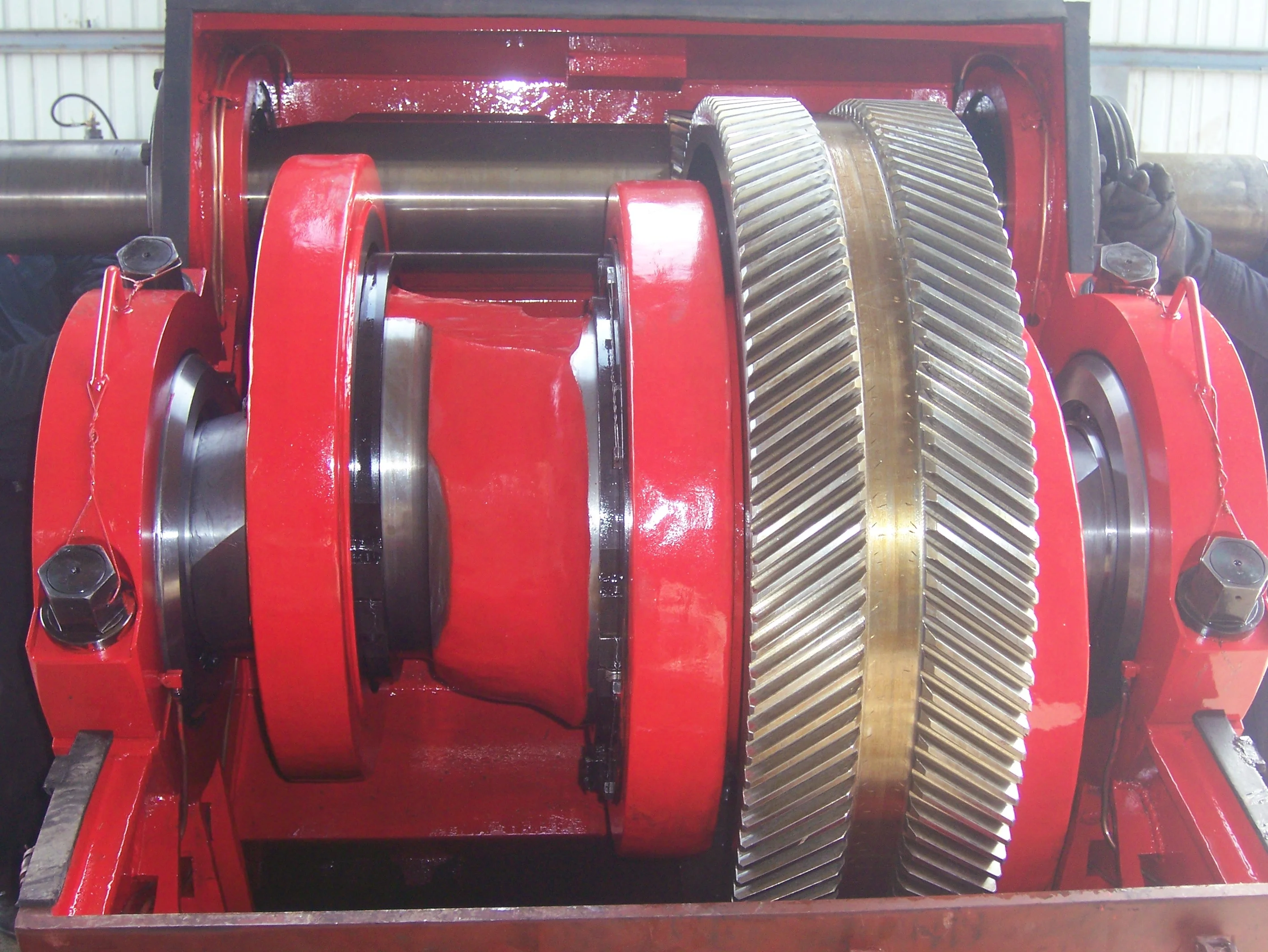
As shown in FIG. 9, the pinion shaft 130 mounts with roller bearings 132 in the power assembly 110 with its free ends 134 extending on both sides of the assembly 110 for coupling to drive components (not shown). As noted previously, the pinion gears 138 on the shaft 130 interface with the bull gears 128 on the crankshaft (120). Preferably, the interface uses helical gearing of opposite hand. In particular, the two pinion gears 138 on the pinion shaft 130 have helical teeth that have an opposite orientation or hand relative to one another. These helical teeth couple in parallel fashion to oppositely oriented helical teeth on the complementary bull gears 128 on the crankshaft 120. (The opposing orientation of helical teeth on the bull gears 128 and pinion gears 138 can best be seen in FIGS. 6A-6B). The helical gearing transfers rotation of the pinion shaft 130 to the crankshaft 120 in a balanced manner. In an alternative embodiment, the pinion shaft 130 can have one pinion gear 138, and the crankshaft 120 can have one bull gear 128. Preferably, these single gears 138/128 use herringbone or double helical gearing of opposite hand to avoid imparting axial thrust to the crankshaft 120.
The cross-section in FIG. 10A shows a crosshead 160 for the quintuplex mud pump. The end of the connecting rod 140 couples by a wrist pin 142 and bearing 144 to a crosshead body 162 that is movable in a crosshead guide 164. A pony rod 166 coupled to the crosshead body 162 extends through a stuffing box gasket 168 on a diaphragm plate 169. An end of this pony rod 166 in turn couples to additional components of the fluid assembly (170) as discussed below.
The cross-section in FIG. 10B shows portion of the fluid assembly 170 for the quintuplex mud pump. An intermediate rod 172 has a clamp 174 that couples to the pony rod (166; FIG. 10A) from the crosshead assembly 160 of FIG. 10A. The opposite end of the rod 172 couples by another clamp to a piston rod 180 having a piston head 182 on its end. Although a piston arrangement is shown, the fluid assembly 170 can use a plunger or any other equivalent arrangement so that the terms piston and plunger can be used interchangeably herein. Moved by the pony rod (166), the piston head 182 moves in a liner 184 communicating with a fluid passage 190. As the piston 182 moves, it pulls mud from a suction manifold 192 through a suction valve 194 into the passage 190 and pushes the mud in the passage 190 to a discharge manifold 198 through a discharge valve 196.
As noted previously, a triplex mud pump produces a total flow variation of about 23%. Because the present mud pump 100 is quintuplex, the pump 100 offers a lower variation in total flow, making the pump 100 better suited for pumping mud and producing less noise that can interfere with MWD and LWD operations. In particular, the quintuplex mud pump 100 can produce a total flow variation as low as about 7%. For example, the quintuplex mud pump 100 can produce a maximum flow level of about 102% during certain crankshaft angles and can produce a minimum flow level of 95% during other crankshaft angles as the pump"s five pistons move in their differing strokes during the crankshaft"s rotation. Being smoother and closer to ideal, the lower total flow variation of 7% produces less pressure changes or “noise” in the pumped mud that can interfere with MWD and LWD operations.
Although a quintuplex mud pump is described above, it will be appreciated that the teachings of the present disclosure can be applied to multiplex mud pumps having at least more than three eccentric sheaves, connecting rods, and fluid assembly pistons. Preferably, the arrangement involves an odd number of these components so such mud pumps may be septuplex, nonuplex, etc. For example, a septuplex mud pump according to the present disclosure may have seven eccentric sheaves, connecting rods, and fluid assembly pistons with at least two bull gears and at least two bearing sheaves on the crankshaft. The bull gears can be arranged between first and second eccentric sheaves and sixth and seventh eccentric sheaves on the crankshaft. The internal main bearings supporting the crankshaft can be positioned between third and fourth eccentric sheaves and the fourth and fifth eccentric sheaves on the crankshaft.
a crankshaft rotatably supported in the pump by a plurality of main bearings, the crankshaft having five eccentric sheaves and a first bull gear disposed thereon, the main bearings including a first internal main bearing sheave disposed between the second and third eccentric sheaves and including a second internal main bearing sheave disposed between the third and fourth eccentric sheaves;
a pinion shaft for driving the crankshaft, the pinion shaft rotatably supported in the pump and having a first pinion gear interfacing with the first bull gear on the crankshaft; and
6. A pump of claim 1, wherein the crankshaft comprises a second bull gear disposed thereon, and wherein the pinion shaft comprises a second pinion gear disposed thereon and interfacing with the second bull gear.
7. A pump of claim 6, wherein the first bull gear is disposed between the first and second eccentric sheaves, and wherein the second bull gear is disposed between the fourth and fifth eccentric sheaves.
8. A pump of claim 6, wherein the five eccentric sheaves, the first and second internal main bearing sheaves, and the first and second bull gears are equidistantly spaced from one another on the crankshaft.
9. A pump of claim 6, wherein the first and second pinion gears comprise helical gearing of opposite hand, and wherein the first and second bull gears comprise helical gearing of opposite hand complementary to the pinion gears.
a crankshaft rotatably supported in the pump by two external main bearings and two internal main bearings, the crankshaft having five eccentric sheaves, two internal main bearing sheaves for the internal main bearings, and at least one bull gear disposed thereon;
13. A pump of claim 11, wherein a first of the main bearing sheaves is disposed between the second and third eccentric sheaves, and wherein a second of the main bearing sheaves is disposed between the third and fourth eccentric sheaves.
16. A pump of claim 11, wherein the at least one bull gear comprises first and second bull gears disposed on the crankshaft, and wherein the at least one pinion gear comprises first and second pinion gears disposed on the crankshaft.
17. A pump of claim 16, wherein the first bull gear is disposed between the first and second eccentric sheaves, and wherein the second bull gear is disposed between the fourth and fifth eccentric sheaves.
18. A pump of claim 16, wherein the five eccentric sheaves, the two internal main bearing sheaves, and the first and second bull gears are equidistantly spaced from one another on the crankshaft.
19. A pump of claim 16, wherein the first and second pinion gears comprise helical gearing of opposite hand, and wherein the first and second bull gears comprise helical gearing of opposite hand complementary to the pinion gears.
a crankshaft rotatably supported in the pump by a plurality of main bearings, the crankshaft having five eccentric sheaves and first and second bull gears disposed thereon, the first bull gear disposed between the first and second eccentric sheaves, the second bull gear disposed between the fourth and fifth eccentric sheaves;
a pinion shaft for driving the crankshaft, the pinion shaft rotatably supported in the pump, the pinion shaft having a first pinion gear interfacing with the first bull gear on the crankshaft and having a second pinion gear interfacing with the second bull gear on the crankshaft; and
26. A pump of claim 21, wherein the main bearings include first and second internal main gearing sheaves disposed on the crankshaft, and wherein the five eccentric sheaves, the two internal main bearing sheaves, and the first and second bull gears are equidistantly spaced from one another on the crankshaft.
27. A pump of claim 21, wherein the first and second pinion gears comprise helical gearing of opposite hand, and wherein the first and second bull gears comprise helical gearing of opposite hand complementary to the pinion gears.
a crankshaft rotatably supported in the pump by a plurality of main bearings, the crankshaft having five eccentric sheaves and first and second bull gears disposed thereon, the main bearings including two internal main bearing sheaves disposed on the crankshaft, wherein the five eccentric sheaves, the two internal main bearing sheaves, and the first and second bull gears are equidistantly spaced from one another on the crankshaft;
a pinion shaft for driving the crankshaft, the pinion shaft rotatably supported in the pump, the pinion shaft having a first pinion gear interfacing with the first bull gear on the crankshaft and having a second pinion gear interfacing with the second bull gear on the crankshaft; and
34. A pump of claim 29, wherein the first and second pinion gears comprise helical gearing of opposite hand, and wherein the first and second bull gears comprise helical gearing of opposite hand complementary to the pinion gears.
"Triplex Mud Pump Parts and Accessories;" Product Information Brochure; copyright 2007 Sunnda LLC; downloaded from http://www.triplexmudpump.com/triplex-mud-pump-parts.php on Sep. 5, 2008.
"Triplex


 8613371530291